EP2122409B1 - Verfahren und system zum kalibrieren und/oder visualisieren einer mehrbildanzeige und zum verringern von ghosting-artefakten - Google Patents
Verfahren und system zum kalibrieren und/oder visualisieren einer mehrbildanzeige und zum verringern von ghosting-artefakten Download PDFInfo
- Publication number
- EP2122409B1 EP2122409B1 EP08710237.2A EP08710237A EP2122409B1 EP 2122409 B1 EP2122409 B1 EP 2122409B1 EP 08710237 A EP08710237 A EP 08710237A EP 2122409 B1 EP2122409 B1 EP 2122409B1
- Authority
- EP
- European Patent Office
- Prior art keywords
- image
- blur
- profile
- optionally
- separating mask
- Prior art date
- Legal status (The legal status is an assumption and is not a legal conclusion. Google has not performed a legal analysis and makes no representation as to the accuracy of the status listed.)
- Not-in-force
Links
Images


Classifications
-
- G—PHYSICS
- G03—PHOTOGRAPHY; CINEMATOGRAPHY; ANALOGOUS TECHNIQUES USING WAVES OTHER THAN OPTICAL WAVES; ELECTROGRAPHY; HOLOGRAPHY
- G03B—APPARATUS OR ARRANGEMENTS FOR TAKING PHOTOGRAPHS OR FOR PROJECTING OR VIEWING THEM; APPARATUS OR ARRANGEMENTS EMPLOYING ANALOGOUS TECHNIQUES USING WAVES OTHER THAN OPTICAL WAVES; ACCESSORIES THEREFOR
- G03B25/00—Viewers, other than projection viewers, giving motion-picture effects by persistence of vision, e.g. zoetrope
- G03B25/02—Viewers, other than projection viewers, giving motion-picture effects by persistence of vision, e.g. zoetrope with interposed lenticular or line screen
-
- G—PHYSICS
- G03—PHOTOGRAPHY; CINEMATOGRAPHY; ANALOGOUS TECHNIQUES USING WAVES OTHER THAN OPTICAL WAVES; ELECTROGRAPHY; HOLOGRAPHY
- G03B—APPARATUS OR ARRANGEMENTS FOR TAKING PHOTOGRAPHS OR FOR PROJECTING OR VIEWING THEM; APPARATUS OR ARRANGEMENTS EMPLOYING ANALOGOUS TECHNIQUES USING WAVES OTHER THAN OPTICAL WAVES; ACCESSORIES THEREFOR
- G03B35/00—Stereoscopic photography
- G03B35/14—Printing apparatus specially adapted for conversion between different types of record
-
- G—PHYSICS
- G03—PHOTOGRAPHY; CINEMATOGRAPHY; ANALOGOUS TECHNIQUES USING WAVES OTHER THAN OPTICAL WAVES; ELECTROGRAPHY; HOLOGRAPHY
- G03B—APPARATUS OR ARRANGEMENTS FOR TAKING PHOTOGRAPHS OR FOR PROJECTING OR VIEWING THEM; APPARATUS OR ARRANGEMENTS EMPLOYING ANALOGOUS TECHNIQUES USING WAVES OTHER THAN OPTICAL WAVES; ACCESSORIES THEREFOR
- G03B35/00—Stereoscopic photography
- G03B35/18—Stereoscopic photography by simultaneous viewing
- G03B35/24—Stereoscopic photography by simultaneous viewing using apertured or refractive resolving means on screens or between screen and eye
-
- H—ELECTRICITY
- H04—ELECTRIC COMMUNICATION TECHNIQUE
- H04N—PICTORIAL COMMUNICATION, e.g. TELEVISION
- H04N13/00—Stereoscopic video systems; Multi-view video systems; Details thereof
- H04N13/30—Image reproducers
- H04N13/302—Image reproducers for viewing without the aid of special glasses, i.e. using autostereoscopic displays
- H04N13/305—Image reproducers for viewing without the aid of special glasses, i.e. using autostereoscopic displays using lenticular lenses, e.g. arrangements of cylindrical lenses
-
- H—ELECTRICITY
- H04—ELECTRIC COMMUNICATION TECHNIQUE
- H04N—PICTORIAL COMMUNICATION, e.g. TELEVISION
- H04N13/00—Stereoscopic video systems; Multi-view video systems; Details thereof
- H04N13/30—Image reproducers
- H04N13/327—Calibration thereof
Definitions
- the present invention in some embodiments thereof, relates to a system and a method for calibrating and/or visualizing a multi image display and, more particularly, but not exclusively, to a system and a method for calibrating and/or visualizing a multi image display which are based on image separating masks.
- One of the methods for creating a multi image display is achieved by spatial or temporal interdigitation of images and/or partial images.
- spatial displays with spatial interdigitation which may be referred to as multi-view displays
- multiple adjoining pixels or their color sub-pixels are grouped to form pixel clusters with each pixel containing a 3D scene from a different perspective, for example see U.S. Pat. No. 6,366,281 Issued on April 2, 2002 .
- An image separating mask such as a barrier, a lenticular lenses array or other optical element, projects the pixel contents of each pixel cluster into space in a fan-shaped manner. Each fan contains the image content of the 3D scene from a certain perspective.
- the overall resolution is not determined by the resolution of the image matrix, but by the coarser pixel cluster resolution. An image with eight perspectives will reduce the resolution to 1/8, for example.
- Another method for creating a multi image display is related to the process of manufacturing elements that incorporate image structures that provide a visual motion to portions of the image as the element is tilted, and in particular to systems for generating the motion image elements, see For example U.S. Patent No. 6,198,544 issued on March 6, 2001 .
- EP 0 897 126 A2 Another conventional method for creating a multi image display is disclosed in EP 0 897 126 A2 .
- a centralized hub station receives a series of images.
- a user views at a terminal remote from the centralized hub station, a simulated lenticular image using at least some images of the series displayed to simulate viewing an actual lenticular image formed from the images of the series.
- an approval is transmitted from the remote terminal to the centralized hub station, for a plurality of the images of the series to be printed as the actual lenticular image.
- the actual lenticular image is then printed at the hub station based on the approval.
- the method comprises the steps of receiving a sequence (52) having a plurality of images, selecting a segment (55) of the sequence according to one or more lenticular viewing measures, and outputting the segment for allowing the lenticular printing.
- a data processor such as a computing platform for executing a plurality of instructions.
- the data processor includes a volatile memory for storing instructions and/or data and/or a non-volatile storage, for example, a magnetic hard-disk and/or removable media, for storing instructions and/or data.
- a network connection is provided as well.
- a display and/or a user input device such as a keyboard or mouse are optionally provided as well.
- the present invention relates to a system and a method for calibrating and/or visualizing a multi image display and, more particularly, but not exclusively, to a system and a method for calibrating and/or visualizing a multi image display which are based on image separating masks.
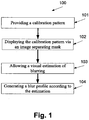
- a method and a system for identifying one or more degradation profiles such as a blur profile, that may be used for calibrating a multi image display.
- the method is based on a calibration pattern that is displayed to an evaluator, such as a system operator or an image capturing device, through a certain image separating mask.
- an image separating mask means a lenticular lenses array, a parallax barrier, a multi image display screen, an array of lenses for integral photography (IP), for example as described in U.S. Patent Application No. 5,800,907, filed on May 23, 1996 and any display for displaying a multi dimensional image.
- Such a display allows the evaluator to provide a visual estimation of the blur that is brought about at least by an image separating mask.
- the blur may also be affected by printing artifacts, paper quality, and in some embodiments, artifacts which are related to an element that projects or displays one or more images via the image separating mask.
- the visual estimation is based on the appearance of the calibration pattern and/or elements thereof. Now, after the visual estimation is provided, the degradation profile, which is optionally the blur profile, is generated according to the visual estimation.
- the blur profile is designed for calibrating one or more images which are displayed through the same image separating mask or one that has the same optical profile as the image separating mask which has been used during the aforementioned visual estimation.
- such a method may be used for identifying a blur profile that is adjusted to a certain optical profile of a specific image separating mask. Furthermore, such a method may also be used for identifying other optical, display, and/or printing profiles, such as banding profile, which are adjusted according to optical aberrations which are brought about by the specific image separating mask or according to printing artifacts which are brought about by the printing and/or copying device that is used for generating calibrated images. It should be noted that such an embodiment may be used for calibrating a printer and/or a copier of a multi image display article.
- this method is based on a calibration pattern which is displayed to an evaluator through an image separating mask.
- the displaying allows the evaluator, as outlined above and described below, to visually estimate artifacts which are brought about by an image separating mask.
- the visual estimation is used for simulating the blur occurring within the display when displaying images which are designed to be displayed via the image separating mask or a via a similar image separating mask.
- the blurring allows the displaying of the images in a manner that visualizes the appearance thereof through the image separating mask.
- blurring means adding blur to the images, mixing the images in a way that creates ghosting artifacts, for example by overlaying one or more images on one or more other images, and/or mixing the strips of an interlaced image or overlaying features of one strip of an interlaced image on another strip of the interlaced image.
- the blurring effect is achieved by blurring the interlaced image or any other processing that creates a weighted overlay of the images.
- Such a method allows emulating the appearance through the image separating mask of the interlaced image or any other image format that combines of the images.
- a user such as a customer, an editor, and a photographer, may upload an interlaced image to a remote server, such as a web server, optionally using a client terminal, such as a personal computer, and the remote server may use the blur profile for blurring the uploaded interlaced image to create the emulation images.
- the user may upload images which are interlaced by the remote server, optionally before the aforementioned blurring.
- the user may upload information that is used by the remote server or another server to create interlaced images.
- the blurring is performed to emulate the appearance of a multi image display that is based on these images.
- the blurred images or any product or segment thereof is retrieved to the user, optionally allowing her to preview the multi image display artifacts on her personal client terminal.
- a preview may allow the user to approve the printing and/or the copying and/or display of the multi image display without seeing it.
- Such an embodiment may facilitate the ordering of a multi image display using the Internet, for example using a website.
- an image separating mask means a lenticular lens array, an optical barrier, a parallax barrier, and/or any other display panel for displaying multiple images, such as sterescopic images.
- the image separating mask has a vertical and/or a horizontal structure, optionally periodic, for channeling images in a plurality of directions.
- the method allows identification of a blur profile, which may be used for creating a blurring image transformation.
- the blurring transformation is implemented by convolving the interlaced images with a blur filter, such as a Gaussian or Lorentz distribution based filter, or any other conversion that is based on one or more visually and/or optically evaluated measurements.
- the blurring image transformation is implemented by mixing strips of an interlaced image or by mixing the images designated for display as a weighted average, for example as described in relation to equation 2 below.
- a blur profile For brevity, such a blurring image transformation, or any other conversion may be referred to herein as a blur profile.
- the blur profile represents the blur that is brought about by at least an image separating mask and optionally printing artifacts. Paper quality, and in some embodiments artifacts which are brought about by a displaying element and/or a projecting element.
- a calibration pattern is provided. As further described below, a number of calibration patterns may be used.
- the calibration pattern is displayed in the multi image display, for example through an image separating mask to a user and/or to an image capturing device, such as a camera.
- This display allows the user and/or to the image capturing device to visually estimate characteristics, such as intensity or visibility, of one or more features that indicates the blur and/or geometry that is brought about by at least an image separating mask, as shown at 103, optionally as described below.
- an image capturing device means a digital camera or any other device that uses an image sensor, such as charge coupled device (CCD) sensor and a complementary metal oxide semiconductor (CMOS) sensor, for capturing a digital image.
- CCD charge coupled device
- CMOS complementary metal oxide semiconductor
- Such a blur profile may be used for blurring and/or de-blurring, which may be understood herein as de-ghosting, one or more interlaced images or any other image or a segment thereof that is, designated to be displayed in the multi image display.
- An example for Such an Interlaced image is an interlaced image for lenticular printing that depicts a scene from a number of angles and/or a motion of one or more objects.
- Another example is an interlaced image for a sequence of images that depict a three-dimensional (3D) scene that is projected on the image separating mask display, for instance see Wojciech Matusik et al.
- 3D TV A Scalable System for Real-Time Acquisition, Transmission, and Autostereoscopic Display of Dynamic Scenes, Mitsubishi Electric Research Laboratories, Cambridge, MA .
- a 3D scene my be understood herein as a scene that depicts one or more objects from a number of angles and/or a motion in or of one or more objects and/or a flipping between at least two different images.
- a 3D scene means a scene that is displayed in three dimensions along a period and/or a scene that is displayed from a number of point of views (POVs).
- the 3D scene is a static scene, for example a scene that is depicted by an interlaced image that is printed on and/or attached in front of the image separating mask.
- the 3D scene is a dynamic sene, for example a 3D scene that is projected on the image separating mask display, see Wojciech Matusik et. AI.
- 3D TV A Scalable System for Real-Time Acquisition, Transmission, and Autostereoscopic Display of Dynamic Scenes, Mitsubishi Electric Research Laboratories, Cambridge, MA.
- the 3D scene is a dynamic scene in which a plurality of different videos is displayed, each video being displayed to a different angle.
- the blur profile is used for emulating one or more images that visualize the views displayed by a multi image display which achieved using the image separating mask.
- a visualization which may be displayed to a user on a 2D display, such as a screen of a personal computer or any other client terminal, and/or printed on a lenticular lenses array and/or a commonly used printing media, allows the user see how a still image and/or a sequence of images may be look like through a image separating mask and/or when projected on an image separating mask.
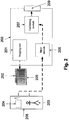
- Fig. 2 is a schematic illustration of a calibrating system 200 for identifying a blur profile for de-ghosting and/or blurring one or more images for a multi image display, according to soine embodiments of the present invention.
- the calibrating system 200 optionally comprises an imaging module 201 for displaying, through or on an image separating mask 205, a calibration pattern 202.
- the calibration pattern may be printed and/or displayed on a display, allowing the evaluation thereof 205.
- the calibration pattern 202 is displayed, to an operator 203 and/or to an image capturing device 204, which may be referred to, jointly or separately, as an evaluator 208.
- the calibration pattern 202 allows the evaluator 208 to estimate visually characteristics, such as intensity or visibility, of one or more features that indicates the blur that is brought about by the image separating mask 205
- the calibrating system 200 includes a calibrating module 207 for estimating a blur profile according to the visual estimation of the user.
- the calibrating system 200 further comprises an input module 206 for allowing the evaluator 208 to input the aforementioned visual estimation.
- the evaluator is a human operator 203, which is referred to herein as an operator 203
- the input module 206 includes a user interface that is displayed to the human operator 203 on a display unit, such as a screen.
- the user interface is a graphic user interface (GUI) that allows the operator 203 to indicate on one or more artifacts that appears on the displayed calibration pattern 202.
- GUI graphic user interface
- the GUI includes an element for each artifact.
- the GUI includes a number of sliders, each designed for allowing the user to indicate on one or more visual measurements.
- the visual estimation of the evaluator may be used to set one or more adjustments to one or more images that is configured for to be displayed through the image separating mask 205, for example as outlined above and/or described below.
- the calibrating system 200 further comprises a calibrating module 207 for calculating a blur profile according to the visual estimation of the user, optionally as outlined above and described below.
- the calibrating module 207 output the blur profile, optionally via an output module 209 to an adjusting module (not shown) for de-ghosting and/or blurring still and/or video images or their interlace according to the blur profile.
- the still and/or video images are designed to be displayed through the image separating mask or through an image separating mask that have one more similar properties. For example, with an image separating mask that has similar properties such as pitch, curvature, refractive index, relative location of the lenticular lenses, transparency and the like.
- the calibrating module 207 uses the estimations of the user for creating a blur profile that takes into account blur that is brought about by the image separating mask and in addition other elements and/or features.
- the user visually estimates characteristics, such as the intensity or the visibility of one or more features in a multi image display with a blur that is brought about also by properties such as printer resolution, type of substrate, type of specular substrate, type of ink, type of ink bleed, type of ink build, edge acuity, and room temperature during printing.
- the adjustment is made according to the one or more visual evaluations which are provided by the evaluator 208.
- Fig 3 is a schematic illustration of a connection between the calibrating system 200, an adjustment server 302, and a client terminal 304 blurring, according to some embodiments of the present invention.
- the components of the calibrating system 200 and the evaluator 208 are as depicted in Fig. 2 , however Fig. 3 depicts a distributed system in which the calibrating system 200 the adjustment server 302 and the client terminal 304 are connected through a computer network 301, such as the Internet and/or an Ethernet.
- the evaluator 208 may use a client terminal that is connected to the computer network 301, such as a personal computer, and hosts or accesses the input module 206 for inputting a visual evaluation of the displayed calibration pattern 202, for example as described below.
- the calibrating system 200 may be used for visualizing a multi image display of the images which are displayed through the image separating mask 205, or a similar image separating mask.
- the calibrating system 200 is connected to a client terminal 304 that displays the visualization to a user.
- the system 100 may define a blur profile that is applied on content of multi-image display that is selected by the user 305.
- the calibrating system 200 provides the blur profile to a web server that hosts a website.
- the website allows the user 305 to visualize, using the client terminal 304, an image or a sequence of images that she selects and/or uploads.
- the visualization allows the user to watch the selected and/or uploaded images as if they have been displayed through the image separating mask or a similar image separating mask.
- the system is connected to a database 404 that is used for storing the uploaded images and/or other images, optionally interlaced, which are designed to be displayed in a multi image display.
- the blur profile which is generated by the calibrating module 207 according to the inputs of the evaluator 208, is used for blurring the selected and or uploaded one or more images and makes them available for the user 305 through the client terminal 304.
- a creator of one or more scenes can use the system to edit the multi-view content without actually projecting or displaying the multi-view content on an Image separating mask or without actually fixating the multi-view content as a multi-view display.
- a creator of a graphic content may see a visualization of one or more multi image display articles which are based on the graphic content that she selected and/or uploaded and uses her client terminal 304 for producing, printing, and/or copying a multi image display that is based on the selected and/or uploaded content.
- the adjusting server 302 adjusts to selected and/or uploaded images according to the blur profile and uses a device, such as a printing device and/or a copying device for generating the multi view display for the creator 305.
- the display is a printed article and the visualization is calculated according to the properties of the specific printing and/or copying device that is used for printing and/or copying the multi image display articles, for example according to one or more printing artifacts which are brought the specific printing about by the printing and/or the copying device.
- the visualization is calculated according to the more printing artifacts which are caused by printing and/or copying media.
- a printing artifact may be a bleed artifact, an edge acuity artifact, a banding artifact, and a gloss non-uniformity artifact.
- a printing artifact profile is created by the calibrating module 207 and used for adjusting the aforementioned visualization.
- the visualization may take various forms, for example by creating one or more animations of the multi image display articles and/or one or more one or more anaglyph images which are adjusted according to the blur profile and optionally according to the printing artifact profile.
- the animations and/or the anaglyph images are outputted as printouts, screen displays, and/or any other form of displaying one or more selected and/or uploaded images and/or anaglyph images.
- U.S. Patent Application 6,389,236, issued on May 14, 2002 see U.S. Patent Application 6,389,236, issued on May 14, 2002 .
- Fig. 2 and to Fig. 4 is an exemplary calibration pattern template and to Fig. 5 that depicts schematic exemplary changeable calibration tiles which are designed to be placed within the calibration pattern template, according to some embodiments of the present invention.
- a user and/or an image capturing device are used for evaluating the blur that is brought about by a certain image separating mask on the basis of the exemplary calibration pattern.
- the imaging unit 201 prints the calibration pattern in a substantially similar manner to the printing of one or more interlaced images which are used for creating the multi image display articles.
- the calibration pattern is placed on the back side of a lenticular lenses array or any other image separating mask that is similar or substantially similar to the aforementioned image separating mask.
- Each white square of the calibration pattern for example shown at 181, is replaced with a changeable calibration tile, for example as shown at Fig. 5 .
- the evaluator 208 captures or views the clarity of the changeable calibration tiles through the image separating mask, and identifies, in each row, the column in which the changeable calibration tile is indistinguishable from the related surrounding frame.
- the calibration pattern is printed directly on the back side of the image separating mask or on a media that is placed closed to the back side of the image separating mask, optionally in a similar manner to the manner that the final interlaced images are printed.
- the changeable calibration tiles contain a non-white segment in at least one view, and white segments in the rest of the views.
- the content of the calibration tiles may represented by a vector E of n values which correspond with the respective views in the image separating mask.
- the calibration pattern depends on the print effects that need to be simulated.
- Figs. 4 and 5 for example, simulate inter-views and intra-views blurring effects.
- the measurement process consists of a set of measurements, each associated with a test.
- Fig. 4 depicts an example of six tests and/or measurements.
- a different pattern is printed within borders of different intensities, as shown at 180.
- the evaluator 208 identifies, for each test and/or row, the column for which the effect of image separating mask causes the internal rectangle to have the same apparent intensity as the surrounding boundary.
- the evaluator 208 may pick one of the columns, for example the median column, or provide all columns as an output. This column represents the estimated quality of the lenticular intensity of the test, as if the evaluator 208 measures intensity.
- Fig. 2 and to Figs. 9-10 are schematic illustrations of respectively an exemplary calibration pattern template 350 having separable artifact identifiers, which may be referred to herein as an artifact calibration template 350 and a GUI 351 for adjusting a blur profile according to the exemplary calibration pattern template 350, according to some embodiments of the present invention.
- the separable artifact identifiers of the exemplary calibration pattern template 350 are nine digits. The operator is asked to view the digits through the multi-view display and to adjust the perceived intensity thereof by using the sliders 352 for adjusting their intensity.
- the user adjusts the perceived intensity of each one of the digits to match an intensity of a respective row 355 by maneuvering a respective slider 352.
- the GUI 351 allows the operator 203 to indicate which one of the visual effects appears in the exemplary calibration pattern template 350.
- the GUI 351 comprises a number of controls, such as shown at 352, each designed to adjust one of the separable artifact identifiers of the artifact calibration template 350, as shown at 353.
- the user is asked to place the calibration pattern template 350 on an image separating mask or to project it thereon.
- the operator 203 evaluates the intensity for each separable artifact identifier that appears on the printed calibration pattern template 350, and uses a respective control, optionally a slider of the GUI 351, to adjust the visualization of the calibration pattern template 354 that is optionally simulated by the GUI 351.
- the adjustment defines the visual evaluation by equalizing the intensity of the visualized calibration pattern template 354 with the printed calibration pattern template 351 that is displayed through or projected on the image separating mask.
- the user adjusts the intensity of each one of the simulated separable artifact identifiers resemble to the intensity of a respective separable artifact identifier on the calibration pattern template 350.
- the blur profile is estimated based on the intensities which have been adjusted by the operator 203, optionally by the calibrating module 207, which is described above.
- the adjusted intensities are used for creating a blur profile by a regression analysis, for example as described in relation to equation 4 below, wherein a set of the adjusted intensity values corresponds with a set of the measurements M j .
- the blur profile kernel K is computed as a normalization of the measurements M j to sum 1.
- the appearance of the calibration pattern depends on the viewing location of the evaluator 208.
- the input module 206 allows the evaluator 208 to provide her and/or it with a current location.
- the current location is optionally used for calibrating the one or more interlaced images and/or the visualization of the one or more interlaced images.
- Fig. 6 is a schematic illustration of the image capturing device 204, the calibration pattern 202, the calibrating system 200 and the image separating mask 205, according to the present invention.
- the image capturing device 204 is connected to a processing unit 210.
- the processing unit 210 is used by the system 200 and the image capturing device 204.
- the evaluator that provides the visual estimation may be a human operator 203 and/or an image capturing device 204.
- the image capturing device 204 optically measures light that is reflected from the calibration pattern and passes through the image separating mask 205.
- the image capturing device uses the processing unit 210 that receives the light measurements and processes them to estimate the blur profile of the display, for example as described below.
- the image capturing device 204 measures the light that is emitted from the calibration pattern that is depicted in Fig. 4 . Since the light passes via the image separating mask 205, it is assured that the measured light has been affected by the optical structure thereof and optionally by its optical aberrations. Optionally, the measured light is affected by other characteristics of the display. For example, when the multi image display includes an image that is printed on an image paper and laminated to the backside of a lenticular lens, then other aspects include the type of paper, the quality of lamination, the type of ink, the half-toning algorithm etc. As described above, in some embodiment of the present invention, the image separating mask 205 includes a lenticular lenses array.
- the pitch of the lenses is provided to the calibrating module 207 in advance.
- data may be stored in the aforementioned database 404 that is connected to the computer network 301 or uploaded by the system operator. Such information is optionally used during the interlacing process which is applied to create the final image for the multi image display.
- the calibration pattern is designed for allowing the image capturing device 204 to measure the light that is emitted therefrom, for example as depicted in Fig. 7 which is an exemplary calibration pattern template 185 and to Fig. 8 that depicts schematic illustrations of the exemplary changeable calibration tiles, according to some embodiments of the present invention.
- the calibration pattern template 185 is similar to the pattern that is used in Fig. 4 ; however, this calibration pattern template 185 further comprises an alignment mark in each one of its corners 193, 194 and sets of mutually shifted centering marks 191 for each row.
- the alignment marks cover an area which is similar to the area of 20 lenticules of image separating mask 205.
- the image separating mask 205 which is optionally a lenticular lens array, may be placed in a manner that the lenticules are oriented horizontally. The tiles are placed in the areas of 190.
- the calibration pattern template 185 is tiled with the aforementioned changeable calibration tiles, creating a reference image.
- the reference image which may be referred to as T, is stored for matching, optionally as described below.
- the calibration pattern template 185 is also displayed in the multi-view display, for example printed on the back side of a image separating mask such as a lenticular lens array and displayed to the image capturing device 204 via the image separating mask 205, for example as shown at Fig. 6 .
- T is defined and a respective calibration pattern is displayed in the multi-view display, for example printed, an image of the displayed/printed calibration pattern is captured.
- an alignment is found between the captured image and the reference image.
- the alignment is optionally identified using the alignment marks 193,194.
- the alignment marks 193, 194 are identified using a pattern recognition detecting method, such as image correlation for pattern recognition, see U.S. Patent No. 5,065,440 issued on November 12, 1991 . Then, a transformation between the locations of the four alignment marks 193, 194 in the captured image and the location thereof in the reference image is derived and used for aligning the captured image.
- the captured image is dynamically resampled to produce the aligned captured image, see U.S. Patent No. 5,394,676 filed on December 22, 1994 . It should be noted that such a transformation is known to the skilled in the art and therefore not further discussed herein. For example, see U.S. Patent No.
- the aligned captured image may be referred to as I w .
- the blur profile may be calculated.
- the aligned captured image may be referred to as I w .
- each one of the rows in the calibration pattern template 185 may be referred to as r k where K denotes the number of the row.
- the convolution kernel K of the blur profile is recovered by using regression analysis as described below, where the brightness values of the surrounding areas O y , defined here, correspond to the measurements' values M j , defined below.
- the evaluator 208 receives an indication of the locations or viewing angle from which the evaluation is supposed to be performed.
- the calibration pattern includes patterns that assist the evaluator 208 to localize her or its position and/or viewing angle in relation to the calibration pattern. Using such patterns for localizing a particular view such as the center view is a standard technique in a lenticular printing process. Such optional processes are known to the skilled in the art and therefore not further described herein.
- the calibration pattern includes a pattern that allows the evaluator 208 to identify its and/or her location and/or viewing angle.
- the evaluator provides information about her and/or it location and/or viewing angle together with the measurements.
- location information may be acquired, for example, by indicating to the evaluator to identify from several interlaced images which image is viewed in the pattern by allowing her or it to identify characteristics, such as brightness, contrast, location of image features and ghosting in the images or by allowing it to use a pattern recognition algorithm such as correlation.
- the appearance of the calibration pattern depends on the viewing location and/or viewing angle of the user.
- the calibration pattern includes one or more templates that assist the evaluator to localize her and/or it position in relation thereto.
- the imaging unit 201 is used for printing a banding calibration pattern 370 that depicts a recurrent pattern of black lines where each line is positioned in a constant distance from another line, for example as shown at Fig. 11 .
- the evaluator 208 now evaluates characteristics of the banding effect, such as the extent of the banding and the shift thereof, which are reflected from the banding calibration pattern 370 and uses the input module 206 for inputting the visual estimation.
- the input module 206 displays a GUI, such as one or more sliders that allows the evaluator 208 to easily input his visual estimation, similarly to the usage of the calibration pattern that is depicted in Fig. 4 .
- a GUI 480 that includes one or more patterns 481 that simulate the banding effects is displayed to the evaluator 208, which is optionally the operator 203.
- the evaluator 208 which is optionally the operator 203, visually evaluates whether she sees banding effects or not and optionally uses one or more sliders 482 for defining characteristics of the banding effect.
- the one or more patterns 481 respond to adjustments which are made by the sliders. The adjustments have been forwarded to the calibrating module 207 that defines a banding profile for calibrating one or more images, as described above.
- the estimated size of the banding profile can be used for reducing the banding effect, for example by simulating a similar banding in input images, for example by presenting a sequence of images that depicts a transition where the transition has one or more characteristics which have been indicated by the user.
- the banding profile is avoiding one or more areas that include more than one optical banding artifact.
- the transition from one view to another starts from one side of the image and progresses to another size.
- the images are designed to be printed on a lenticular lenses array having 5.08 x5,08 centimeters (2x2 inches) and the user indicates that the banding effect is approximately 6.35 centimeters wide (2.5 inches wide) the 2x2 images can be placed such that banding effects will only occur at the spaces between the 5.08 x5.08 centimeters (2x2 inches) images and not in the images themselves.
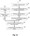
- FIG. 13 is a flowchart of a method for visualizing a multi image display, according to some embodiments of the present invention.
- Blocks 101-104 are as depicted in Fig. 1 , however Fig. 13 further depicts a
- FIG. 13 is a flowchart of a method for visualizing a multi image display, according to some embodiments of the present invention.
- Blocks 101-104 are as depicted in Fig. 1 , however Fig. 13 further depicts a number of blocks that allows the visualization of a multi image display of one or more images, such as interlaced images.
- one or more images that are to be presented simultaneously to different viewing directions, optionally as defined above, are received.
- the images are optionally interlaced.
- the one or more of the interlaced images are blurred using the blur profile that has been calculated in 101-104.
- the blur profile is defined as a convolution filter and the blurring is performed by convoluting it over the interlaced image.
- the one or more blurred interlaced images are visualized.
- the blurred interlaced images are de-interlaced optionally by collecting and/or interpolating the relevant columns from the one or more blurred interlaced images.
- the computational complexity of the process may be reduced.
- only one or more segments of the one or more received images are interlaced; there is no need to create the entire interlaced image. For example, one may create each a portion of the interlaced image and blur only a portion thereof.
- the emulation of the multi image display is implemented by a set of semi transparent images.
- the blur profile is recovered using regression analysis.
- a set of convolution coefficients is recovered using a least squares regression process.
- each one of M l ,...,M k denotes a member of a set of measurements, each corresponding with a measurement that has been identified by the evaluator and each one of P l ,..., P k denotes a member of a set of template vectors.
- the calibration pattern optionally comprises a number of printed templates; each consists of a set of uniform columns. Each one of the template vectors contains intensity values of the printed template columns.
- the aforementioned set of measurements M 1 ,..., M k is determined according to the values which are adjusted by operator 203, for example according to the intensities which are defined by the rectangle selected by the operator for each row as depicted in Fig. 4 and described above, and the template vectors P 1 ,..., P k correspond with a respective separable artifact identifier that is presented to the operator, optionally as described above.
- the aforementioned set of measurements M 1 ,..., M k is determined according to the values, which are adjusted by operator 203 according to the intensities which are defined by the sliders of the GUI that is depicted in Fig. 10 and described above.
- the blurring which is performed at 253, is made using a linear modeling.
- the blur profile which is optionally a convolution kernel, simplifies the measurement process, for example as defined in International Patent Application IL2008/000060 filed on January 15, 2008 .
- the calibration pattern which is optionally as shown at Figs. 4 and 5 , consists a set of uniform columns and each one of the template vectors P l ,...,P k contains the intensity values of the printed template columns.
- a general linear blur function which is optionally defined as a linear function having several basis functions, is defined.
- the set of basis functions includes interpolating functions such as splines, polynomials, Gaussians with a zero mean and a different variance, and the like.
- the blurring which is performed at 253, is made using a non-linear modeling.
- a number of convolution kernels are used, for example as follows: k exp x ⁇ ⁇ where ⁇ and ⁇ are the parameters and k is a normalization factor which is used for normalizing a filter sum, for instance to 1.
- a number of filters are used, optionally including Gaussian filters.
- a blur profile may be defined with a small number of parameters, preferably 1-2 parameters.
- the blur profile can be estimated as follows:
- the one or more simulations are presented to the evaluator using a display device, such as a screen.
- the evaluator can use the input module 206 to adjust one or more blur parameters of the simulations and to visually evaluate its and/or her adjustment.
- the input module 206 is a GUI that is displayed on the aforementioned imaging unit 201 or display device.
- Such a GUI optionally includes virtual sliders, combo boxes, virtual knobs, and/or any other graphic tools that may be used for adjusting the blur.
- the imaging unit 206 is designed to output a plurality of prints, each simulates a blur that is defined by a different set of parameters.
- the calibrating system 200 is designed to calculate a blur profile which may be used for creating a blur filter.
- a blur filter may be used for reducing artifacts such as optical blur artifacts which are caused by image separating masks, for example by lenticular lens array.
- the blur profile may be used for reducing and/or eliminating one or more ghosting artifacts.
- a ghosting artifact means a visual effect in which an image appears to also include elements of at least another image.
- a lenticular lens array light impinging on the lenticules is reflected throughout the lenticular material. Given the convex shape of the lenticules, the light reflects at different angles. This means that even though theoretically only one segment of the printed image is supposed to be viewed for a given viewing angle, the light reflects off other segments of the image so that they, too, may appear to some extent to the viewer.
- Ghosting artifacts which are expressed as blurriness of in-depth objects in 3D images or as overlay of at least one image on another image, are optionally modeled according to the blur profile.
- the ghosting artifacts are reduced from images which are designed to be displayed in a multi image display, such as interlaced images.
- the ghosting artifacts are reduced from images which are designed to be used for creating interlaced images or from segments of images which are designed to be used for creating interlaced images.
- the ghosting artifacts may be reduced, according to the blur profile, in process which may be referred to herein as a de-ghosting process and/or de-blurring process.
- the values of pixels in an interlaced image are linearly combined so that at least one of the coefficients is negative.
- the combined effect of the de-ghosting process and of the blur that is created by the image separating mask, which is optionally a lenticular lens array is significantly lower than the blur that is created without the de-ghosting process.
- g f if f is symmetrical.
- the number of iterations is predefined.
- the number of iterations is dynamically determined according to a halt criterion that may be defined according to the size of s.
- the multi-view display requires an image with halftone format.
- a halftone format means any photomechanical printing surface or the impression therefrom in which detail and tone values are represented by a series of dots in varying size and shape, varying in direct proportion to the intensity of tones they represent.
- An example for such a multi image display is provided in U.S. Patent No. 6,061,179 or in a multi image display such as a lenticular lenses array having one or more images which are attached thereto or printed thereon.
- a halftone format is a format wherein each pixel is represented with a low number of bits. The halftoning or halftone screening process may be used for reproducing an image with a high quality, see for example U.S.
- One example is a printed lenticular display that is produced by a printing device and/or a copying device that receives one or more halftone images as input.
- the de-blurring or de-ghosting is performed as a halftoning process that takes into account the blur profile of the multi-view display.
- the halftoning process is implemented using a least squares halftoning algorithm that is defined according to a modulation transfer function (MTF) and/or a filter that is based on the impulse response of a finite impulse response (FIR) filter, for example as described in US Patent No. 5,475,497 .
- the de-ghosting filter is based on a product of two one-dimensional filters.
- the first one-dimensional filter is the blur profile or any filter that is derived therefrom and the second-one dimensional filter is an impulse response for a filter which is used in modeling human visual perception, for example as Figs. 3 and 4 of US Patent No. 5,475,497 .
- compositions, method or structure may include additional ingredients, steps and/or parts, but only if the additional ingredients, steps and/or parts do not materially alter the basic and novel characteristics of the claimed composition, method or structure.
- a compound or “at least one compound” may include a plurality of compounds, including mixtures thereof.
- range format is merely for convenience and brevity and should not be construed as an inflexible limitation on the scope of the invention. Accordingly, the description of a range should be considered to have specifically disclosed all the possible subranges as well as individual numerical values within that range. For example, description of a range such as from 1 to 6 should be considered to have specifically disclosed subranges such as from 1 to 3, from 1 to 4, from 1 to 5, from 2 to 4, from 2 to 6, from 3 to 6 etc., as well as individual numbers within that range, for example, 1, 2, 3, 4, 5, and 6. This applies regardless of the breadth of the range.
Claims (12)
- Verfahren zum Identifizieren eines Weichzeichnungsprofils einer Mehrbildanzeige mit einer ersten Bildtrennmaske, das die Schritte umfasst:a) Anzeigen (102) eines Kalibrierungsmusters (202) durch eine zweite Bildtrennmaske (205);b) Ermöglichen (103), dass ein menschlicher Beobachter (203) eine visuelle Schätzung bereitstellt, die eine Weichzeichnung indiziert, die durch die zweite Bildtrennmaske an dem Kalibrierungsmuster (202) bewirkt wird; undc) Erzeugen (104) eines Weichzeichnungsprofils zumindest der ersten Bildtrennmaske gemäß der visuellen Schätzung;wobei die erste und die zweite Bildtrennmaske (205) ein im Wesentlichen ähnliches optisches Profil aufweisen.
- Verfahren nach Anspruch 1, das des Weiteren des Schritte des Verwendens des Weichzeichnungsprofils für zumindest eines von Verringern zumindest eines Geisterbildartefakts von der Mehrbildanzeige und Verwenden des Weichzeichnungsprofils zum Nachbilden des Erscheinungsbildes zumindest eines Bildes auf einer Mehrbildanzeige.
- Verfahren nach Anspruch 2, wobei das Verringern unter Verwendung des Weichzeichnungsprofils in einem Halbtonprozess durchgeführt wird.
- Verfahren nach einem der Ansprüche 1 bis 3, das des Weiteren den Schritt des Erzeugens eines Elements umfasst, das aus einer Gruppe ausgewählt ist, bestehend aus: einem Weichzeichnungsfilter, einer Bildweichzeichnungstransformation, einer Bildumwandlungsfunktion und einer Verarbeitung zumindest eines Bilds gemäß dem Element.
- Verfahren nach einem der Ansprüche 1 bis 4, wobei die zweite Bildtrennmaske (205) die erste Bildtrennmaske ist.
- Verfahren nach einem der Ansprüche 1 bis 5, wobei das Kalibrierungsmuster (202) gedruckt wird, wobei das Kalibrierungsmuster (202) eine Druckweichzeichnung aufweist, die durch zumindest ein Druckartefakt des optischen Profils verursacht wird.
- Verfahren nach einem der Ansprüche 1 bis 6, wobei jede der ersten und zweiten Bildtrennmaske aus einer Gruppe ausgewählt ist, bestehend aus: einer Lentikularlinsenanordnung, einer optischen Barriere, einer Parallaxenbarriere, einer Anordnung von Linsen für integrale Photographie und einer beliebigen Anzeige zum Anzeigen eines mehrdimensionalen Bildes.
- Verfahren nach einem der Ansprüche 1 bis 7, das des Weiteren den Schritt des Verwendens des Weichzeichnungsprofils zum Entfernen von Geisterbildern aus dem zumindest einem Bild gemäß der visuellen Schätzung, wodurch ein Geisterbildartefakt verringert wird, das durch die erste Bildtrennmaske verursacht wurde.
- System (200) zum Identifizieren eines Weichzeichnungsprofils einer Mehrbildanzeige, das umfasst:ein Eingabemodul (206), das so konfiguriert ist, dass es eine visuelle Schätzung einer Weichzeichnung, die durch zumindest eine Bildtrennmaske an einem Kalibrierungsmuster (202) bewirkt wird, von einem menschlichen Beobachter empfängt, wobei die visuelle Schätzung bereitgestellt wird, wenn das Kalibrierungsmuster (202) über die Bildtrennmaske angezeigt wird;ein Kalibrierungsmodul (207), das so konfiguriert ist, dass es das Weichzeichnungsprofil gemäß der visuellen Schätzung erzeugt;eine Ausgabeeinheit (209) zum Ausgeben des Weichzeichnungsprofils, um zumindest eines von Verringern eines Geisterbildartefakts der Mehrbildanzeige und Visualisieren der Mehrbildanzeige zu ermöglichen; undeine Druckvorrichtung oder eine Kopiervorrichtung zum Erzeugen eines Zeilensprungbildes, das so konzipiert ist, dass es durch die Mehrbildanzeige angezeigt wird, unter Verwendung des Weichzeichnungsprofils.
- System (200) nach Anspruch 9, wobei die Bildtrennmaske ein optisches Profil aufweist, wobei die Mehrbildanzeige eine zusätzliche Bildtrennmaske mit dem optischen Profil aufweist, wobei die Mehrbildanzeige durch Anzeigen des zumindest einen Bildes durch die zusätzliche Bildtrennmaske gebildet wird.
- System (200) nach Anspruch 10, wobei das optische Profil so konfiguriert ist, dass es ein Element definiert, das aus einer Gruppe ausgewählt ist, bestehend aus: einer Neigung, einer Krümmung, einer Brechungsindexform, einer relativen Position der Lentikularlinse, einer Transparenz, eines Papiertyps, eines Haftmitteltyps, eines Druckertyps und dergleichen.
- System (200) nach einem der Ansprüche 9 bis 11, das des Weiteren eine Client-Schnittstelle umfasst, die so konfiguriert ist, dass sie eine Visualisierung der Mehrbildanzeige erzeugt und die Visualisierung über ein Netzwerk an ein Client-Endgerät sendet, damit ein Benutzer die Visualisierung ansehen kann.
Applications Claiming Priority (4)
| Application Number | Priority Date | Filing Date | Title |
|---|---|---|---|
| US89151207P | 2007-02-25 | 2007-02-25 | |
| US95124207P | 2007-07-23 | 2007-07-23 | |
| US2749308P | 2008-02-11 | 2008-02-11 | |
| PCT/IL2008/000237 WO2008102366A2 (en) | 2007-02-25 | 2008-02-25 | A method and a system for calibrating and/or visualizing a multi image display and for reducing ghosting artifacts |
Publications (2)
| Publication Number | Publication Date |
|---|---|
| EP2122409A2 EP2122409A2 (de) | 2009-11-25 |
| EP2122409B1 true EP2122409B1 (de) | 2016-12-07 |
Family
ID=39710604
Family Applications (1)
| Application Number | Title | Priority Date | Filing Date |
|---|---|---|---|
| EP08710237.2A Not-in-force EP2122409B1 (de) | 2007-02-25 | 2008-02-25 | Verfahren und system zum kalibrieren und/oder visualisieren einer mehrbildanzeige und zum verringern von ghosting-artefakten |
Country Status (4)
| Country | Link |
|---|---|
| US (1) | US8520060B2 (de) |
| EP (1) | EP2122409B1 (de) |
| JP (1) | JP5202546B2 (de) |
| WO (1) | WO2008102366A2 (de) |
Families Citing this family (53)
| Publication number | Priority date | Publication date | Assignee | Title |
|---|---|---|---|---|
| EP2122409B1 (de) | 2007-02-25 | 2016-12-07 | Humaneyes Technologies Ltd. | Verfahren und system zum kalibrieren und/oder visualisieren einer mehrbildanzeige und zum verringern von ghosting-artefakten |
| US9035968B2 (en) | 2007-07-23 | 2015-05-19 | Humaneyes Technologies Ltd. | Multi view displays and methods for producing the same |
| KR101095670B1 (ko) * | 2009-07-06 | 2011-12-19 | (주) 비전에스티 | 스테레오 카메라의 고속 칼리브레이션 및 렉티피케이션 방법 및 장치 |
| DE102009054706A1 (de) * | 2009-12-15 | 2011-06-16 | Secco-Spezial-Elektronik Und Computer-Cooperations-Gmbh | Vorrichtung zur räumlichen Darstellung und Verfahren zu ihrer Herstellung |
| JP5515988B2 (ja) * | 2010-04-05 | 2014-06-11 | ソニー株式会社 | 信号処理装置、信号処理方法、表示装置及びプログラム |
| CN102946790A (zh) * | 2010-04-22 | 2013-02-27 | 麻省理工学院 | 用于屈光评估的近眼工具 |
| JP5656059B2 (ja) * | 2010-08-25 | 2015-01-21 | Nltテクノロジー株式会社 | 実装精度検査方法及びその検査方法を用いる検査装置 |
| FR2965444B1 (fr) * | 2010-09-24 | 2012-10-05 | St Microelectronics Grenoble 2 | Transmission de video 3d sur une infrastructure de transport historique |
| US9361717B2 (en) * | 2010-10-19 | 2016-06-07 | Humaneyes Technologies Ltd. | Methods and systems of generating an interlaced composite image |
| KR101819621B1 (ko) | 2010-10-19 | 2018-01-17 | 휴먼아이즈 테크놀로지즈 리미티드 | 인터레이스된 복합 이미지를 발생시키는 방법 및 시스템 |
| KR101868654B1 (ko) * | 2011-01-22 | 2018-06-18 | 휴먼아이즈 테크놀로지즈 리미티드 | 렌티큘러 인쇄 및 디스플레이에서 흐림 아티팩트를 감소시키는 방법 및 시스템 |
| EP2615838B1 (de) * | 2012-01-12 | 2019-08-21 | SeeFront GmbH | Kalibrierung eines autostereoskopischen Anzeigesystems |
| CN102663718B (zh) * | 2012-03-19 | 2015-06-24 | 清华大学 | 一种全局不一致图像去模糊的方法及系统 |
| US9069177B2 (en) | 2012-06-15 | 2015-06-30 | Innocom Technology(Shenzhen)Co., Ltd. | Two dimensional/ three dimensional switchable display module and display deice having the same |
| US9774839B2 (en) * | 2013-08-30 | 2017-09-26 | Glasses.Com Inc. | Systems and methods for color correction of images captured using a mobile computing device |
| EP2902211B1 (de) * | 2014-01-31 | 2019-01-02 | OCE-Technologies B.V. | Geisterbildausgleich in Reliefbildern für direktionale Drucke |
| EP2989988B1 (de) * | 2014-08-29 | 2017-10-04 | Samsung Medison Co., Ltd. | Ultraschallbildanzeigevorrichtung und verfahren zur anzeige eines ultraschallbildes |
| WO2016045104A1 (zh) * | 2014-09-26 | 2016-03-31 | 深圳市泛彩溢实业有限公司 | 全息三维显示系统和方法 |
| KR102238741B1 (ko) * | 2015-01-06 | 2021-04-12 | 삼성디스플레이 주식회사 | 표시 패널의 발광 상태 측정 방법 및 표시 패널의 발광 상태 보정 방법 |
| JP6465752B2 (ja) * | 2015-05-29 | 2019-02-06 | キヤノン株式会社 | 制御装置、制御方法、及びプログラム |
| US10885802B2 (en) * | 2015-08-07 | 2021-01-05 | Gleim Conferencing, Llc | System and method for validating honest test taking |
| US10484674B2 (en) * | 2015-09-05 | 2019-11-19 | Leia Inc. | Supersampled 3D display with improved angular resolution |
| TWI604073B (zh) * | 2016-08-09 | 2017-11-01 | 盟立自動化股份有限公司 | 適用於有機發光二極體蒸鍍製程並可用以校正影像擷取模組之定位精度之光罩結構 |
| US10380395B2 (en) * | 2016-09-30 | 2019-08-13 | Synaptics Incorporated | Optical sensor with angled reflectors |
| AU2016259442A1 (en) * | 2016-11-18 | 2018-06-07 | Canon Kabushiki Kaisha | Method and system for reproducing visual content |
| US10375306B2 (en) | 2017-07-13 | 2019-08-06 | Zillow Group, Inc. | Capture and use of building interior data from mobile devices |
| US10530997B2 (en) | 2017-07-13 | 2020-01-07 | Zillow Group, Inc. | Connecting and using building interior data acquired from mobile devices |
| KR102401168B1 (ko) | 2017-10-27 | 2022-05-24 | 삼성전자주식회사 | 3차원 디스플레이 장치의 파라미터 캘리브레이션 방법 및 장치 |
| US10643386B2 (en) | 2018-04-11 | 2020-05-05 | Zillow Group, Inc. | Presenting image transition sequences between viewing locations |
| US10708507B1 (en) | 2018-10-11 | 2020-07-07 | Zillow Group, Inc. | Automated control of image acquisition via use of acquisition device sensors |
| CA3058602C (en) | 2018-10-11 | 2023-01-24 | Zillow Group, Inc. | Automated mapping information generation from inter-connected images |
| US10809066B2 (en) | 2018-10-11 | 2020-10-20 | Zillow Group, Inc. | Automated mapping information generation from inter-connected images |
| US11107205B2 (en) | 2019-02-18 | 2021-08-31 | Samsung Electronics Co., Ltd. | Techniques for convolutional neural network-based multi-exposure fusion of multiple image frames and for deblurring multiple image frames |
| US11062436B2 (en) | 2019-05-10 | 2021-07-13 | Samsung Electronics Co., Ltd. | Techniques for combining image frames captured using different exposure settings into blended images |
| US11095829B2 (en) | 2019-06-11 | 2021-08-17 | Samsung Electronics Co., Ltd. | Apparatus and method for high dynamic range (HDR) image creation of dynamic scenes using graph cut-based labeling |
| US11243656B2 (en) | 2019-08-28 | 2022-02-08 | Zillow, Inc. | Automated tools for generating mapping information for buildings |
| US11164368B2 (en) | 2019-10-07 | 2021-11-02 | Zillow, Inc. | Providing simulated lighting information for three-dimensional building models |
| US11164361B2 (en) | 2019-10-28 | 2021-11-02 | Zillow, Inc. | Generating floor maps for buildings from automated analysis of visual data of the buildings' interiors |
| US11676344B2 (en) | 2019-11-12 | 2023-06-13 | MFTB Holdco, Inc. | Presenting building information using building models |
| US10825247B1 (en) | 2019-11-12 | 2020-11-03 | Zillow Group, Inc. | Presenting integrated building information using three-dimensional building models |
| US11405549B2 (en) | 2020-06-05 | 2022-08-02 | Zillow, Inc. | Automated generation on mobile devices of panorama images for building locations and subsequent use |
| US11430094B2 (en) | 2020-07-20 | 2022-08-30 | Samsung Electronics Co., Ltd. | Guided multi-exposure image fusion |
| US11514674B2 (en) | 2020-09-04 | 2022-11-29 | Zillow, Inc. | Automated analysis of image contents to determine the acquisition location of the image |
| US11592969B2 (en) | 2020-10-13 | 2023-02-28 | MFTB Holdco, Inc. | Automated tools for generating building mapping information |
| US11481925B1 (en) | 2020-11-23 | 2022-10-25 | Zillow, Inc. | Automated determination of image acquisition locations in building interiors using determined room shapes |
| US11252329B1 (en) | 2021-01-08 | 2022-02-15 | Zillow, Inc. | Automated determination of image acquisition locations in building interiors using multiple data capture devices |
| CA3142154A1 (en) | 2021-01-08 | 2022-07-08 | Zillow, Inc. | Automated determination of image acquisition locations in building interiors using multiple data capture devices |
| US11836973B2 (en) | 2021-02-25 | 2023-12-05 | MFTB Holdco, Inc. | Automated direction of capturing in-room information for use in usability assessment of buildings |
| US11790648B2 (en) | 2021-02-25 | 2023-10-17 | MFTB Holdco, Inc. | Automated usability assessment of buildings using visual data of captured in-room images |
| US11501492B1 (en) | 2021-07-27 | 2022-11-15 | Zillow, Inc. | Automated room shape determination using visual data of multiple captured in-room images |
| KR20230018075A (ko) | 2021-07-29 | 2023-02-07 | 삼성전자주식회사 | 시차 광학 소자의 캘리브레이션 장치 및 방법 |
| US11842464B2 (en) | 2021-09-22 | 2023-12-12 | MFTB Holdco, Inc. | Automated exchange and use of attribute information between building images of multiple types |
| US11830135B1 (en) | 2022-07-13 | 2023-11-28 | MFTB Holdco, Inc. | Automated building identification using floor plans and acquired building images |
Family Cites Families (75)
| Publication number | Priority date | Publication date | Assignee | Title |
|---|---|---|---|---|
| US3538632A (en) | 1967-06-08 | 1970-11-10 | Pictorial Prod Inc | Lenticular device and method for providing same |
| US5107346A (en) | 1988-10-14 | 1992-04-21 | Bowers Imaging Technologies, Inc. | Process for providing digital halftone images with random error diffusion |
| US5212546A (en) * | 1990-07-03 | 1993-05-18 | Electronics For Imaging, Inc. | Color correction system employing reference pictures |
| US5469536A (en) * | 1992-02-25 | 1995-11-21 | Imageware Software, Inc. | Image editing system including masking capability |
| US5583950A (en) * | 1992-09-16 | 1996-12-10 | Mikos, Ltd. | Method and apparatus for flash correlation |
| US5363043A (en) * | 1993-02-09 | 1994-11-08 | Sunnybrook Health Science Center | Producing dynamic images from motion ghosts |
| US5657111A (en) * | 1993-05-28 | 1997-08-12 | Image Technology International, Inc. | 3D photographic printer with a chemical processor |
| EP0684585B1 (de) * | 1994-04-22 | 2003-02-05 | Canon Kabushiki Kaisha | Bilderzeugungsverfahren und -gerät |
| EP0999463A1 (de) | 1994-11-28 | 2000-05-10 | Smartlight Limited | Verbessertes Anzeigegerät |
| US5774599A (en) * | 1995-03-14 | 1998-06-30 | Eastman Kodak Company | Method for precompensation of digital images for enhanced presentation on digital displays with limited capabilities |
| US5737087A (en) | 1995-09-29 | 1998-04-07 | Eastman Kodak Company | Motion-based hard copy imaging |
| US7190518B1 (en) * | 1996-01-22 | 2007-03-13 | 3Ality, Inc. | Systems for and methods of three dimensional viewing |
| US6144972A (en) * | 1996-01-31 | 2000-11-07 | Mitsubishi Denki Kabushiki Kaisha | Moving image anchoring apparatus which estimates the movement of an anchor based on the movement of the object with which the anchor is associated utilizing a pattern matching technique |
| US5841952A (en) * | 1996-04-29 | 1998-11-24 | Sienna Imaging, Inc. | Parallel segment printing in a photographic process printer |
| IL127534A (en) | 1996-06-13 | 2001-08-26 | Leuven K U Res & Dev | Method and system for acquiring a three-dimensional shape description |
| US5818975A (en) * | 1996-10-28 | 1998-10-06 | Eastman Kodak Company | Method and apparatus for area selective exposure adjustment |
| US6006041A (en) * | 1997-03-12 | 1999-12-21 | Canon Kabushiki Kaisha | Display device |
| US5867322A (en) * | 1997-08-12 | 1999-02-02 | Eastman Kodak Company | Remote approval of lenticular images |
| AUPO894497A0 (en) * | 1997-09-02 | 1997-09-25 | Xenotech Research Pty Ltd | Image processing method and apparatus |
| JP2001522098A (ja) * | 1997-10-30 | 2001-11-13 | ドクター・バルデヴェグ・ゲーエムベーハー | 画像処理方法および装置 |
| US6690268B2 (en) * | 2000-03-02 | 2004-02-10 | Donnelly Corporation | Video mirror systems incorporating an accessory module |
| GB2336963A (en) * | 1998-05-02 | 1999-11-03 | Sharp Kk | Controller for three dimensional display and method of reducing crosstalk |
| US6590635B2 (en) * | 1998-06-19 | 2003-07-08 | Creo Inc. | High resolution optical stepper |
| US7092003B1 (en) * | 1999-01-21 | 2006-08-15 | Mel Siegel | 3-D imaging arrangements |
| GB9901365D0 (en) * | 1999-01-22 | 1999-03-10 | Isis Innovations Ltd | Confocal microscopy apparatus and method |
| US6571000B1 (en) * | 1999-11-29 | 2003-05-27 | Xerox Corporation | Image processing algorithm for characterization of uniformity of printed images |
| JP2001186549A (ja) | 1999-12-27 | 2001-07-06 | Nippon Hoso Kyokai <Nhk> | 立体表示クロストーク量測定装置 |
| US6490094B2 (en) * | 2000-03-17 | 2002-12-03 | Zograph, Llc | High acuity lens system |
| US7039289B1 (en) * | 2000-05-19 | 2006-05-02 | Optinetrics, Inc. | Integrated optic devices and processes for the fabrication of integrated optic devices |
| JP2001346226A (ja) | 2000-06-02 | 2001-12-14 | Canon Inc | 画像処理装置、立体写真プリントシステム、画像処理方法、立体写真プリント方法、及び処理プログラムを記録した媒体 |
| JP2002123160A (ja) * | 2000-10-16 | 2002-04-26 | Sony Corp | ホログラフィックステレオグラム印刷受注システム及び方法 |
| US20020075566A1 (en) | 2000-12-18 | 2002-06-20 | Tutt Lee W. | 3D or multiview light emitting display |
| US6569580B2 (en) * | 2001-03-13 | 2003-05-27 | Diverging Technologies, Inc. | Binary and phase-shift photomasks |
| GB0119176D0 (en) * | 2001-08-06 | 2001-09-26 | Ocuity Ltd | Optical switching apparatus |
| ATE383033T1 (de) * | 2001-10-02 | 2008-01-15 | Seereal Technologies Gmbh | Autostereoskopisches display |
| KR100576752B1 (ko) * | 2001-10-09 | 2006-05-03 | 에이에스엠엘 마스크툴즈 비.브이. | 2차원 피처모델 캘리브레이션 및 최적화 방법 |
| US7043073B1 (en) * | 2001-10-19 | 2006-05-09 | Zebra Imaging, Inc. | Distortion correcting rendering techniques for autostereoscopic displays |
| US7130864B2 (en) * | 2001-10-31 | 2006-10-31 | Hewlett-Packard Development Company, L.P. | Method and system for accessing a collection of images in a database |
| US7088396B2 (en) | 2001-12-21 | 2006-08-08 | Eastman Kodak Company | System and camera for creating lenticular output from digital images |
| CA2380105A1 (en) * | 2002-04-09 | 2003-10-09 | Nicholas Routhier | Process and system for encoding and playback of stereoscopic video sequences |
| GB2389728A (en) * | 2002-06-11 | 2003-12-17 | Sharp Kk | Parallax barrier for autostereoscopic display |
| GB2390948A (en) * | 2002-07-17 | 2004-01-21 | Sharp Kk | Autostereoscopic display |
| US6896655B2 (en) * | 2002-08-05 | 2005-05-24 | Eastman Kodak Company | System and method for conditioning the psychological state of a subject using an adaptive autostereoscopic display |
| DE20213819U1 (de) * | 2002-09-03 | 2002-11-21 | 4D Vision Gmbh | Optische Baugruppe |
| NZ521505A (en) | 2002-09-20 | 2005-05-27 | Deep Video Imaging Ltd | Multi-view display |
| JP2004119919A (ja) * | 2002-09-30 | 2004-04-15 | Hitachi Ltd | 半導体薄膜および半導体薄膜の製造方法 |
| TW583600B (en) * | 2002-12-31 | 2004-04-11 | Ind Tech Res Inst | Method of seamless processing for merging 3D color images |
| US7839430B2 (en) * | 2003-03-12 | 2010-11-23 | Siegbert Hentschke | Autostereoscopic reproduction system for 3-D displays |
| DE10316733A1 (de) * | 2003-04-08 | 2004-10-28 | X3D Technologies Gmbh | Verfahren zur Umrüstung eines 2D-Bildschirmes zu einem autostereoskopischen Bildschirm und Adapterrahmen |
| US7266248B2 (en) * | 2003-08-08 | 2007-09-04 | Hewlett-Packard Development Company, L.P. | Method and apparatus for generating data representative of an image |
| GB2405519A (en) * | 2003-08-30 | 2005-03-02 | Sharp Kk | A multiple-view directional display |
| US7574070B2 (en) * | 2003-09-30 | 2009-08-11 | Canon Kabushiki Kaisha | Correction of subject area detection information, and image combining apparatus and method using the correction |
| US20050073530A1 (en) * | 2003-10-03 | 2005-04-07 | Jay Kapur | System and method for display calibration |
| US20050083516A1 (en) * | 2003-10-20 | 2005-04-21 | Baker Henry H. | Method and system for calibration of optics for an imaging device |
| US7506267B2 (en) * | 2003-12-23 | 2009-03-17 | Intel Corporation | Compose rate reduction for displays |
| US8098275B2 (en) * | 2003-12-30 | 2012-01-17 | The Trustees Of The Stevens Institute Of Technology | Three-dimensional imaging system using optical pulses, non-linear optical mixers and holographic calibration |
| EP1728116B1 (de) | 2004-03-12 | 2012-09-19 | Koninklijke Philips Electronics N.V. | Anzeigeeinrichtung mit mehreren ansichten |
| EP1596410A1 (de) * | 2004-03-30 | 2005-11-16 | LG Electronics Inc. | Plasma-Anzeigetafel und Herstellungsverfahren derselben |
| FR2868901B1 (fr) * | 2004-04-07 | 2006-09-22 | Eastman Kodak Co | Procede de montage automatique de sequences de video et appareil pour la mise en oeuvre du procede |
| JP2005309560A (ja) * | 2004-04-19 | 2005-11-04 | Fuji Photo Film Co Ltd | 画像処理方法および装置並びにプログラム |
| US7283231B2 (en) * | 2004-07-20 | 2007-10-16 | Duke University | Compressive sampling and signal inference |
| US7835562B2 (en) * | 2004-07-23 | 2010-11-16 | General Electric Company | Methods and apparatus for noise reduction filtering of images |
| DE202005021436U1 (de) * | 2004-11-02 | 2008-02-14 | Cascade Microtech, Inc., Beaverton | Optisch verbessertes digitales Abbildungssystem |
| JP4188900B2 (ja) * | 2004-11-15 | 2008-12-03 | ザイオソフト株式会社 | 医療画像処理プログラム |
| JP2006162666A (ja) | 2004-12-02 | 2006-06-22 | Toshiba Corp | 立体画像表示装置およびそのレンズ位置合わせ方法 |
| US20060139447A1 (en) * | 2004-12-23 | 2006-06-29 | Unkrich Mark A | Eye detection system and method for control of a three-dimensional display |
| GB2422737A (en) * | 2005-01-26 | 2006-08-02 | Sharp Kk | Multiple-view display and display controller |
| KR101318024B1 (ko) * | 2005-06-24 | 2013-10-14 | 리얼디 인크. | 비 주요 조망구역에 대하여 증가된 선예도를 갖는자동입체영상 디스플레이 |
| KR101335172B1 (ko) * | 2005-10-27 | 2013-12-05 | 리얼디 인크. | 자동입체영상 렌티큘라 어레이 및 디스플레이 스크린의차동 팽창에 대한 온도 보정 |
| US20070196028A1 (en) * | 2006-02-22 | 2007-08-23 | Nik Software, Inc. | Multi-Purpose Digital Image Editing Tools Using Background Processing |
| US8013870B2 (en) * | 2006-09-25 | 2011-09-06 | Adobe Systems Incorporated | Image masks generated from local color models |
| US7995861B2 (en) * | 2006-12-13 | 2011-08-09 | Adobe Systems Incorporated | Selecting a reference image for images to be joined |
| EP2106564A2 (de) | 2007-01-15 | 2009-10-07 | Humaneyes Technologies Ltd. | Verfahren und system zum linsenrasterdruck |
| EP2122409B1 (de) | 2007-02-25 | 2016-12-07 | Humaneyes Technologies Ltd. | Verfahren und system zum kalibrieren und/oder visualisieren einer mehrbildanzeige und zum verringern von ghosting-artefakten |
| US9035968B2 (en) | 2007-07-23 | 2015-05-19 | Humaneyes Technologies Ltd. | Multi view displays and methods for producing the same |
-
2008
- 2008-02-25 EP EP08710237.2A patent/EP2122409B1/de not_active Not-in-force
- 2008-02-25 US US12/528,328 patent/US8520060B2/en not_active Expired - Fee Related
- 2008-02-25 JP JP2009550774A patent/JP5202546B2/ja not_active Expired - Fee Related
- 2008-02-25 WO PCT/IL2008/000237 patent/WO2008102366A2/en active Application Filing
Non-Patent Citations (1)
| Title |
|---|
| None * |
Also Published As
| Publication number | Publication date |
|---|---|
| JP5202546B2 (ja) | 2013-06-05 |
| EP2122409A2 (de) | 2009-11-25 |
| WO2008102366A2 (en) | 2008-08-28 |
| WO2008102366A3 (en) | 2008-12-31 |
| US8520060B2 (en) | 2013-08-27 |
| US20100066817A1 (en) | 2010-03-18 |
| JP2010521081A (ja) | 2010-06-17 |
Similar Documents
| Publication | Publication Date | Title |
|---|---|---|
| EP2122409B1 (de) | Verfahren und system zum kalibrieren und/oder visualisieren einer mehrbildanzeige und zum verringern von ghosting-artefakten | |
| EP2666300B1 (de) | Verfahren und systeme zur reduzierung von trübenden artefakten im lentikulardruck und anzeige | |
| KR101655349B1 (ko) | 허상을 감소시키기 위한 방법 및 시스템 | |
| US7557824B2 (en) | Method and apparatus for generating a stereoscopic image | |
| US8189035B2 (en) | Method and apparatus for rendering virtual see-through scenes on single or tiled displays | |
| JP4649219B2 (ja) | 立体画像生成装置 | |
| TW201333533A (zh) | 用於模擬自動立體顯示裝置的顯示設備及方法 | |
| KR101852209B1 (ko) | 자동입체 디스플레이 및 그 제조방법 | |
| JP2006115198A (ja) | 立体画像生成プログラム、立体画像生成システムおよび立体画像生成方法 | |
| JP5859654B2 (ja) | 立体視及びマルチビューにおけるモデルベースのクロストーク低減 | |
| US20120194905A1 (en) | Image display apparatus and image display method | |
| WO2007020600A2 (en) | A stereoscopic display apparatus | |
| CN114554174B (zh) | 裸眼立体图像测量系统、图像处理方法及装置、显示设备 | |
| Boev et al. | Comparative study of autostereoscopic displays for mobile devices | |
| EP2630631B1 (de) | Verfahren und systeme zur erzeugung eines zusammengesetzten zeilensprungbildes | |
| JP5492311B2 (ja) | 視点画像生成装置、視点画像生成方法及び立体画像印画装置 | |
| JP6823984B2 (ja) | 画像生成装置及びプログラム | |
| Patana et al. | Adaptive 3D color anaglyph generation for printing | |
| Liu | Augmenting digital displays with computation |
Legal Events
| Date | Code | Title | Description |
|---|---|---|---|
| PUAI | Public reference made under article 153(3) epc to a published international application that has entered the european phase |
Free format text: ORIGINAL CODE: 0009012 |
|
| 17P | Request for examination filed |
Effective date: 20090924 |
|
| AK | Designated contracting states |
Kind code of ref document: A2 Designated state(s): AT BE BG CH CY CZ DE DK EE ES FI FR GB GR HR HU IE IS IT LI LT LU LV MC MT NL NO PL PT RO SE SI SK TR |
|
| 17Q | First examination report despatched |
Effective date: 20100609 |
|
| DAX | Request for extension of the european patent (deleted) | ||
| REG | Reference to a national code |
Ref country code: DE Ref legal event code: R079 Ref document number: 602008047740 Country of ref document: DE Free format text: PREVIOUS MAIN CLASS: G02B0027220000 Ipc: H04N0013040000 |
|
| RIC1 | Information provided on ipc code assigned before grant |
Ipc: H04N 13/04 20060101AFI20160622BHEP |
|
| GRAP | Despatch of communication of intention to grant a patent |
Free format text: ORIGINAL CODE: EPIDOSNIGR1 |
|
| INTG | Intention to grant announced |
Effective date: 20160805 |
|
| GRAS | Grant fee paid |
Free format text: ORIGINAL CODE: EPIDOSNIGR3 |
|
| GRAA | (expected) grant |
Free format text: ORIGINAL CODE: 0009210 |
|
| AK | Designated contracting states |
Kind code of ref document: B1 Designated state(s): AT BE BG CH CY CZ DE DK EE ES FI FR GB GR HR HU IE IS IT LI LT LU LV MC MT NL NO PL PT RO SE SI SK TR |
|
| REG | Reference to a national code |
Ref country code: GB Ref legal event code: FG4D |
|
| REG | Reference to a national code |
Ref country code: CH Ref legal event code: EP Ref country code: AT Ref legal event code: REF Ref document number: 852622 Country of ref document: AT Kind code of ref document: T Effective date: 20161215 |
|
| REG | Reference to a national code |
Ref country code: IE Ref legal event code: FG4D |
|
| REG | Reference to a national code |
Ref country code: DE Ref legal event code: R096 Ref document number: 602008047740 Country of ref document: DE |
|
| PG25 | Lapsed in a contracting state [announced via postgrant information from national office to epo] |
Ref country code: LV Free format text: LAPSE BECAUSE OF FAILURE TO SUBMIT A TRANSLATION OF THE DESCRIPTION OR TO PAY THE FEE WITHIN THE PRESCRIBED TIME-LIMIT Effective date: 20161207 |
|
| REG | Reference to a national code |
Ref country code: LT Ref legal event code: MG4D |
|
| REG | Reference to a national code |
Ref country code: NL Ref legal event code: MP Effective date: 20161207 |
|
| PG25 | Lapsed in a contracting state [announced via postgrant information from national office to epo] |
Ref country code: GR Free format text: LAPSE BECAUSE OF FAILURE TO SUBMIT A TRANSLATION OF THE DESCRIPTION OR TO PAY THE FEE WITHIN THE PRESCRIBED TIME-LIMIT Effective date: 20170308 Ref country code: NO Free format text: LAPSE BECAUSE OF FAILURE TO SUBMIT A TRANSLATION OF THE DESCRIPTION OR TO PAY THE FEE WITHIN THE PRESCRIBED TIME-LIMIT Effective date: 20170307 Ref country code: LT Free format text: LAPSE BECAUSE OF FAILURE TO SUBMIT A TRANSLATION OF THE DESCRIPTION OR TO PAY THE FEE WITHIN THE PRESCRIBED TIME-LIMIT Effective date: 20161207 Ref country code: SE Free format text: LAPSE BECAUSE OF FAILURE TO SUBMIT A TRANSLATION OF THE DESCRIPTION OR TO PAY THE FEE WITHIN THE PRESCRIBED TIME-LIMIT Effective date: 20161207 |
|
| REG | Reference to a national code |
Ref country code: AT Ref legal event code: MK05 Ref document number: 852622 Country of ref document: AT Kind code of ref document: T Effective date: 20161207 |
|
| PG25 | Lapsed in a contracting state [announced via postgrant information from national office to epo] |
Ref country code: HR Free format text: LAPSE BECAUSE OF FAILURE TO SUBMIT A TRANSLATION OF THE DESCRIPTION OR TO PAY THE FEE WITHIN THE PRESCRIBED TIME-LIMIT Effective date: 20161207 Ref country code: ES Free format text: LAPSE BECAUSE OF FAILURE TO SUBMIT A TRANSLATION OF THE DESCRIPTION OR TO PAY THE FEE WITHIN THE PRESCRIBED TIME-LIMIT Effective date: 20161207 Ref country code: FI Free format text: LAPSE BECAUSE OF FAILURE TO SUBMIT A TRANSLATION OF THE DESCRIPTION OR TO PAY THE FEE WITHIN THE PRESCRIBED TIME-LIMIT Effective date: 20161207 Ref country code: BE Free format text: LAPSE BECAUSE OF NON-PAYMENT OF DUE FEES Effective date: 20170228 |
|
| PG25 | Lapsed in a contracting state [announced via postgrant information from national office to epo] |
Ref country code: NL Free format text: LAPSE BECAUSE OF FAILURE TO SUBMIT A TRANSLATION OF THE DESCRIPTION OR TO PAY THE FEE WITHIN THE PRESCRIBED TIME-LIMIT Effective date: 20161207 |
|
| PG25 | Lapsed in a contracting state [announced via postgrant information from national office to epo] |
Ref country code: IS Free format text: LAPSE BECAUSE OF FAILURE TO SUBMIT A TRANSLATION OF THE DESCRIPTION OR TO PAY THE FEE WITHIN THE PRESCRIBED TIME-LIMIT Effective date: 20170407 Ref country code: SK Free format text: LAPSE BECAUSE OF FAILURE TO SUBMIT A TRANSLATION OF THE DESCRIPTION OR TO PAY THE FEE WITHIN THE PRESCRIBED TIME-LIMIT Effective date: 20161207 Ref country code: RO Free format text: LAPSE BECAUSE OF FAILURE TO SUBMIT A TRANSLATION OF THE DESCRIPTION OR TO PAY THE FEE WITHIN THE PRESCRIBED TIME-LIMIT Effective date: 20161207 Ref country code: EE Free format text: LAPSE BECAUSE OF FAILURE TO SUBMIT A TRANSLATION OF THE DESCRIPTION OR TO PAY THE FEE WITHIN THE PRESCRIBED TIME-LIMIT Effective date: 20161207 Ref country code: CZ Free format text: LAPSE BECAUSE OF FAILURE TO SUBMIT A TRANSLATION OF THE DESCRIPTION OR TO PAY THE FEE WITHIN THE PRESCRIBED TIME-LIMIT Effective date: 20161207 |
|
| PG25 | Lapsed in a contracting state [announced via postgrant information from national office to epo] |
Ref country code: BE Free format text: LAPSE BECAUSE OF FAILURE TO SUBMIT A TRANSLATION OF THE DESCRIPTION OR TO PAY THE FEE WITHIN THE PRESCRIBED TIME-LIMIT Effective date: 20161207 Ref country code: PL Free format text: LAPSE BECAUSE OF FAILURE TO SUBMIT A TRANSLATION OF THE DESCRIPTION OR TO PAY THE FEE WITHIN THE PRESCRIBED TIME-LIMIT Effective date: 20161207 Ref country code: IT Free format text: LAPSE BECAUSE OF FAILURE TO SUBMIT A TRANSLATION OF THE DESCRIPTION OR TO PAY THE FEE WITHIN THE PRESCRIBED TIME-LIMIT Effective date: 20161207 Ref country code: PT Free format text: LAPSE BECAUSE OF FAILURE TO SUBMIT A TRANSLATION OF THE DESCRIPTION OR TO PAY THE FEE WITHIN THE PRESCRIBED TIME-LIMIT Effective date: 20170407 Ref country code: BG Free format text: LAPSE BECAUSE OF FAILURE TO SUBMIT A TRANSLATION OF THE DESCRIPTION OR TO PAY THE FEE WITHIN THE PRESCRIBED TIME-LIMIT Effective date: 20170307 Ref country code: AT Free format text: LAPSE BECAUSE OF FAILURE TO SUBMIT A TRANSLATION OF THE DESCRIPTION OR TO PAY THE FEE WITHIN THE PRESCRIBED TIME-LIMIT Effective date: 20161207 |
|
| REG | Reference to a national code |
Ref country code: DE Ref legal event code: R097 Ref document number: 602008047740 Country of ref document: DE |
|
| PG25 | Lapsed in a contracting state [announced via postgrant information from national office to epo] |
Ref country code: MC Free format text: LAPSE BECAUSE OF FAILURE TO SUBMIT A TRANSLATION OF THE DESCRIPTION OR TO PAY THE FEE WITHIN THE PRESCRIBED TIME-LIMIT Effective date: 20161207 |
|
| REG | Reference to a national code |
Ref country code: CH Ref legal event code: PL |
|
| PLBE | No opposition filed within time limit |
Free format text: ORIGINAL CODE: 0009261 |
|
| STAA | Information on the status of an ep patent application or granted ep patent |
Free format text: STATUS: NO OPPOSITION FILED WITHIN TIME LIMIT |
|
| PG25 | Lapsed in a contracting state [announced via postgrant information from national office to epo] |
Ref country code: CH Free format text: LAPSE BECAUSE OF NON-PAYMENT OF DUE FEES Effective date: 20170228 Ref country code: LI Free format text: LAPSE BECAUSE OF NON-PAYMENT OF DUE FEES Effective date: 20170228 |
|
| 26N | No opposition filed |
Effective date: 20170908 |
|
| REG | Reference to a national code |
Ref country code: DE Ref legal event code: R079 Ref document number: 602008047740 Country of ref document: DE Free format text: PREVIOUS MAIN CLASS: H04N0013040000 Ipc: H04N0013300000 |
|
| REG | Reference to a national code |
Ref country code: IE Ref legal event code: MM4A |
|
| PG25 | Lapsed in a contracting state [announced via postgrant information from national office to epo] |
Ref country code: DK Free format text: LAPSE BECAUSE OF FAILURE TO SUBMIT A TRANSLATION OF THE DESCRIPTION OR TO PAY THE FEE WITHIN THE PRESCRIBED TIME-LIMIT Effective date: 20161207 Ref country code: SI Free format text: LAPSE BECAUSE OF FAILURE TO SUBMIT A TRANSLATION OF THE DESCRIPTION OR TO PAY THE FEE WITHIN THE PRESCRIBED TIME-LIMIT Effective date: 20161207 |
|
| REG | Reference to a national code |
Ref country code: FR Ref legal event code: ST Effective date: 20171031 |
|
| PG25 | Lapsed in a contracting state [announced via postgrant information from national office to epo] |
Ref country code: LU Free format text: LAPSE BECAUSE OF NON-PAYMENT OF DUE FEES Effective date: 20170225 |
|
| PG25 | Lapsed in a contracting state [announced via postgrant information from national office to epo] |
Ref country code: FR Free format text: LAPSE BECAUSE OF NON-PAYMENT OF DUE FEES Effective date: 20170228 |
|
| PG25 | Lapsed in a contracting state [announced via postgrant information from national office to epo] |
Ref country code: IE Free format text: LAPSE BECAUSE OF NON-PAYMENT OF DUE FEES Effective date: 20170225 |
|
| PG25 | Lapsed in a contracting state [announced via postgrant information from national office to epo] |
Ref country code: MT Free format text: LAPSE BECAUSE OF NON-PAYMENT OF DUE FEES Effective date: 20170225 |
|
| PG25 | Lapsed in a contracting state [announced via postgrant information from national office to epo] |
Ref country code: HU Free format text: LAPSE BECAUSE OF FAILURE TO SUBMIT A TRANSLATION OF THE DESCRIPTION OR TO PAY THE FEE WITHIN THE PRESCRIBED TIME-LIMIT; INVALID AB INITIO Effective date: 20080225 |
|
| PG25 | Lapsed in a contracting state [announced via postgrant information from national office to epo] |
Ref country code: CY Free format text: LAPSE BECAUSE OF NON-PAYMENT OF DUE FEES Effective date: 20161207 |
|
| PG25 | Lapsed in a contracting state [announced via postgrant information from national office to epo] |
Ref country code: TR Free format text: LAPSE BECAUSE OF FAILURE TO SUBMIT A TRANSLATION OF THE DESCRIPTION OR TO PAY THE FEE WITHIN THE PRESCRIBED TIME-LIMIT Effective date: 20161207 |
|
| PGFP | Annual fee paid to national office [announced via postgrant information from national office to epo] |
Ref country code: GB Payment date: 20200219 Year of fee payment: 13 Ref country code: DE Payment date: 20200219 Year of fee payment: 13 |
|
| REG | Reference to a national code |
Ref country code: DE Ref legal event code: R119 Ref document number: 602008047740 Country of ref document: DE |
|
| GBPC | Gb: european patent ceased through non-payment of renewal fee |
Effective date: 20210225 |
|
| PG25 | Lapsed in a contracting state [announced via postgrant information from national office to epo] |
Ref country code: DE Free format text: LAPSE BECAUSE OF NON-PAYMENT OF DUE FEES Effective date: 20210901 Ref country code: GB Free format text: LAPSE BECAUSE OF NON-PAYMENT OF DUE FEES Effective date: 20210225 |