EP1382461A1 - Vorrichtung zum Kerben eines aus zusammengepressten Druckbogen gebildeten Buchblockrückens - Google Patents
Vorrichtung zum Kerben eines aus zusammengepressten Druckbogen gebildeten Buchblockrückens Download PDFInfo
- Publication number
- EP1382461A1 EP1382461A1 EP20020405627 EP02405627A EP1382461A1 EP 1382461 A1 EP1382461 A1 EP 1382461A1 EP 20020405627 EP20020405627 EP 20020405627 EP 02405627 A EP02405627 A EP 02405627A EP 1382461 A1 EP1382461 A1 EP 1382461A1
- Authority
- EP
- European Patent Office
- Prior art keywords
- cutting teeth
- book block
- carrier
- spine
- cutting
- Prior art date
- Legal status (The legal status is an assumption and is not a legal conclusion. Google has not performed a legal analysis and makes no representation as to the accuracy of the status listed.)
- Granted
Links
- 230000036346 tooth eruption Effects 0.000 claims abstract description 30
- 238000005520 cutting process Methods 0.000 claims abstract description 17
- 230000001154 acute effect Effects 0.000 claims abstract description 3
- 239000011230 binding agent Substances 0.000 claims description 5
- 239000000853 adhesive Substances 0.000 abstract description 4
- 230000001070 adhesive effect Effects 0.000 abstract description 4
- 230000000694 effects Effects 0.000 description 3
- 238000004026 adhesive bonding Methods 0.000 description 2
- 230000002349 favourable effect Effects 0.000 description 2
- 239000003292 glue Substances 0.000 description 2
- 101100008049 Caenorhabditis elegans cut-5 gene Proteins 0.000 description 1
- 238000004873 anchoring Methods 0.000 description 1
- 238000007654 immersion Methods 0.000 description 1
- 238000003754 machining Methods 0.000 description 1
- 238000004519 manufacturing process Methods 0.000 description 1
- 238000000034 method Methods 0.000 description 1
- 238000003801 milling Methods 0.000 description 1
- 238000005457 optimization Methods 0.000 description 1
Images


Classifications
-
- B—PERFORMING OPERATIONS; TRANSPORTING
- B42—BOOKBINDING; ALBUMS; FILES; SPECIAL PRINTED MATTER
- B42C—BOOKBINDING
- B42C5/00—Preparing the edges or backs of leaves or signatures for binding
- B42C5/04—Preparing the edges or backs of leaves or signatures for binding by notching or roughening
-
- Y—GENERAL TAGGING OF NEW TECHNOLOGICAL DEVELOPMENTS; GENERAL TAGGING OF CROSS-SECTIONAL TECHNOLOGIES SPANNING OVER SEVERAL SECTIONS OF THE IPC; TECHNICAL SUBJECTS COVERED BY FORMER USPC CROSS-REFERENCE ART COLLECTIONS [XRACs] AND DIGESTS
- Y10—TECHNICAL SUBJECTS COVERED BY FORMER USPC
- Y10T—TECHNICAL SUBJECTS COVERED BY FORMER US CLASSIFICATION
- Y10T83/00—Cutting
- Y10T83/929—Tool or tool with support
- Y10T83/9372—Rotatable type
- Y10T83/9391—Notching tool
Definitions
- the invention relates to a device for notching one compressed printed sheet formed book block spine, with one about an approximately vertical axis of rotation to the book block spine rotating notching tool that when passing a book block on the conveyor path of a perfect binder for making notches has cutting teeth immersed in the spine of the book block, the front on a support of the notching tool are attached.
- this goal US 4,741,236 A with a device for notching a book block spine.
- the device consists of a conveyor for moving a block of books a conveyor path, with the back of the book block for editing protrudes.
- Opposite the book block spine is one Notching device arranged in the conveying direction of the Book block inclined disc, which around a vertical Axis is driven.
- This axis of rotation is hollow and concentric to it is a shaft within the axis of rotation stored, which is one end for driving a notching tool extends beyond the disc.
- the notching tool is there from three milling blades arranged side by side, which at Passing the spine of the book block transverse to the conveying direction leave notches or grooves of different depths, that are perpendicular to the inclined disc. That is, with everyone Rotation of the disc produces three notches, which are each at different depths in the back of the book block extend.
- the inclined grooves help one more favorable anchorage of the glue on the back of a book block.
- the device used for this is of a relatively high Associated effort.
- the present invention has been an improvement both anchoring the glue in the back of a book block as well the clamp effect compared to US 4,741,236 A to the task made.
- the object is achieved in that the Carrier of the notching tool at least two on the axis of rotation Has opposing cutting teeth that are pointed in one Angles are aligned to a cutting circle plane.
- At least one of the cutting teeth advantageously has one for Cutting circle center of the notching tool inclined position, so that when processing an alternating opposite The notches are inclined.
- the same structure of the notches can arise if at least one of the cutting teeth one from the cutting circle center radially outwardly inclined position.
- the carrier of the notching tool can be one to the conveyor path vertically arranged axis of rotation so that the Book block spines of two opposite each other at a distance Cutting teeth may be trimmed at the same time becomes.
- the distance resp. the structure of the notches along the spine of the book block can via the speed adjustment of the notching tool and / or the speed of the book blocks the path of the perfect binder.
- FIGS. 1 and 2 show a device for notching a printed sheet compressed at least on the side flanks of a book block spine 1 of a book block 2 (partially visible), the book block 2 being placed upright or with the book block spine 1 facing the notching device in the direction F along a conveying path an adhesive binder is transported.
- the book block 2 passed clamped in a clamp of the perfect binder, in which the folded edges of the individual printed sheets have been removed by machining, so that the book block spine 1 has a largely flat structure for the subsequent notching process.
- the book block spine 1 and 2 for notching the book block spine 1 essentially consists of a, preferably disc-like carrier 3, which is connected to a drive shaft 4 and has two cutting teeth 5 facing the book block spine 1, which, as can be seen in the exemplary embodiment shown, can be seen , vis-à-vis of the axis of rotation 6 are attached to the carrier 3 above.
- the cutting teeth 5 protruding in the same direction of inclination on the carrier 3 result in a notch structure as illustrated in FIG. 3, that is to say one pair of notches each has oppositely oriented notches or the notches which are lined up in the longitudinal direction of a book block spine have mutually opposing depressions.
- the depressions could alternately be of different lengths and it would be conceivable to attach more than two cutting teeth 5 to the carrier 3.
- the distance between the notches depends on the conveying speed of the book blocks and the rotational speed of the cutting teeth 5, the rotational direction of which is indicated by arrow R in FIG. 2.
- the carrier 3, which is of circular design to avoid uneven rotational forces, is set in a slightly inclined position with respect to the passing book block spine 1 of the book block 2, so that only one cutting tooth 5 dips into the book block spine 1 at the same point across the book block spine width, the immersion distance being at least the length of the Book block thickness and leaves an arcuate notch.
- the cutting teeth 5 are fastened at an acute angle ⁇ with respect to the cutting plane formed by them by a shaft 9 in recesses 7, 8 of the carrier 3, preferably fastened interchangeably.
- the recesses 7, 8 are triangular in cross section and have approximately the width of a shank 9 of a cutting tooth 5 in the sense of a lateral holder.
- the cutting teeth 5 can be soldered or screwed to the support 3 on their shaft 9.
- FIG. 3 conveys an image of those shown in FIGS. 1 and 2 Notch structure produced device shown on a Book block spines, with the notch sections clearly showing that the edge of the book block spine 1 is approximately in the notch the axis of rotation 6 of the notching tool.
- the cutting teeth 5 are attached to the periphery of a disk-shaped carrier 3, which has the cross-sectional shape of a truncated cone.
- the cutting teeth 5 are fastened or exchangeably fastened along a surface line of the carrier 3 and the cutting teeth 5 are the same as those shown in FIGS. 1 and 2.
- the cutting teeth 5 could also be fastened in recesses. Another difference compared to FIGS.
- the axis of rotation 6 or the drive shaft 4 connected to the carrier 3 is oriented approximately perpendicular to the conveying path or to the book block spine 1, so that in each case both of the cutting teeth opposite each other on the axis of rotation 6 Cut 5 notches in the book block spine 1, both cutting teeth 5 being equally involved in the production of the reflecting notch section pairs 10 (see also FIGS. 6a and 6b), the arrangement of which can be seen in FIG. 4.
- the notch structure is not symmetrical to the longitudinal axis of the book block spine 1.
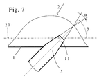
- FIG. 7 shows an enlarged representation of FIG. 4- is the cross-sectional geometry in the cutting area of a cutting tooth 5, as shown for example in 4 is used.
- the cutting tip 11 has a wedge shape in cross section with an angle ⁇ so that the chips from the spine of the book block 1 are free of interference have it dug out. Otherwise the cutting geometry is the same the cutting tooth 5 a turning tool.
Landscapes
- Engineering & Computer Science (AREA)
- Mechanical Engineering (AREA)
- Confectionery (AREA)
- Folding Of Thin Sheet-Like Materials, Special Discharging Devices, And Others (AREA)
- Perforating, Stamping-Out Or Severing By Means Other Than Cutting (AREA)
- Nonmetal Cutting Devices (AREA)
Abstract
Description
Gestrichene oder für Kunstdruck geeignete Papiere erschweren die Klebebindung eines Buchblockrückens aufgrund der hierzu unzureichenden Eigenschaften.
- Fig. 1
- eine Seitenansicht der Vorrichtung,
- Fig. 2
- einen Grundriss der Vorrichtung gemäss Fig. 1,
- Fig. 3
- eine Kerbstruktur an einem Buchblockrücken nach der Bearbeitung mit einer Vorrichtung gemäss Fig. 1 und 2,
- Fig. 4
- eine Seitenansicht einer alternativen Vorrichtung,
- Fig. 5
- einen Grundriss der Vorrichtung gemäss Fig. 4,
- Fig. 6a
- eine abschnittsweise Kerbstruktur an einem Buchblockrücken nach der Bearbeitung mit einer Vorrichtung gemäss Fig. 4 und 5,
- Fig. 6b
- eine abschnittsweise alternative Kerbstruktur an einem Buchblockrücken nach der Bearbeitung mit einer Vorrichtung gemäss Fig. 4 und 5 sowie
- Fig. 7
- eine vergrösserte Darstellung eines Schneidzahns.
Die in den Fig. 1 und 2 dargestellte Vorrichtung zum Kerben des Buchblockrückens 1 besteht im Wesentlichen aus einem, vorzugsweise scheibenartigen Träger 3, der mit einer Antriebswelle 4 verbunden ist und zwei dem Buchblockrücken 1 zugewandte Schneidzähne 5 aufweist, die, wie im dargestellten Ausführungsbeispiel erkennbar, vis-ä-vis von der Drehachse 6 am Träger 3 vorstehend befestigt sind. Die in gleicher Neigungsrichtung an dem Träger 3 vorstehenden Schneidzähne 5 ergeben eine Kerbstruktur, wie sie in Fig. 3 veranschaulicht ist, d.h. jeweils ein Kerbenpaar weist entgegengesetzt ausgerichtete Kerben auf bzw. die in Längsrichtung eines Buchblockrückens aneinandergereihten Kerben weisen wechselweise entgegengerichtete Vertiefungen auf. Die Vertiefungen könnten wechselweise unterschiedlich lang ausgebildet sein und es wäre denkbar, mehr als zwei Schneidzähne 5 an dem Träger 3 zu befestigen. Der Abstand der Kerben richtet sich nach der Fördergeschwindigkeit der Buchblöcke und der Umlaufgeschwindigkeit der Schneidzähne 5, deren Umlaufrichtung durch Pfeil R in Fig. 2 vermerkt ist. Der zur Meidung ungleichmässiger Rotationskräfte kreisrund ausgebildete Träger 3 ist gegenüber dem passierenden Buchblockrücken 1 des Buchblocks 2 in eine leichte Schräglage versetzt, sodass jeweils nur ein Schneidzahn 5 an der gleichen Stelle über die Buchblockrückenbreite in den Buchblockrücken 1 eintaucht, wobei die Eintauchstrecke wenigstens die Länge der Buchblockdicke aufweist und eine kreisbogenförmige Kerbe hinterlässt. Die Schneidzähne 5 sind in einem gegenüber der von ihnen gebildeten Schneidebene spitzen Winkel β durch einen Schaft 9 in Ausnehmungen 7, 8 des Trägers 3 befestigt, vorzugsweise austauschbar befestigt. Die Ausnehmungen 7, 8 sind im Querschnitt dreieckförmig und weisen im Sinne einer seitlichen Halterung etwa die Breite eines Schaftes 9 eines Schneidzahnes 5 auf. Die Schneidzähne 5 können an ihrem Schaft 9 an dem Träger 3 festgelötet oder festgeschraubt sein.
Gemäss Fig. 4 sind die Schneidzähne 5 am Umfang eines scheibenförmigen Trägers 3 befestigt, der die Querschnittsform eines Kegelstumpfs aufweist. Die Schneidzähne 5 sind entlang einer Mantellinie des Trägers 3 befestigt bzw. auswechselbar befestigt und es handelt sich um die gleichen Schneidzähne 5, die schon in den Fig. 1 und 2 gezeichnet sind. Selbstverständlich könnten die Schneidzähne 5 auch in Ausnehmungen befestigt sein.
Ein weiterer Unterschied gegenüber den Fig. 1 und 2 besteht darin, dass die Drehachse 6 bzw. die mit dem Träger 3 verbundene Antriebswelle 4 etwa senkrecht zum Förderpfad bzw. zum Buchblockrücken 1 ausgerichtet ist, sodass jeweils beide der sich an der Drehachse 6 gegenüberliegenden Schneidzähne 5 Kerben in den Buchblockrücken 1 schneiden, wobei beide Schneidzähne 5 gleichermassen an der Herstellung der sich widerspiegelnden Kerbabschnittspaare 10 beteiligt sind (siehe auch Fig. 6a und 6b), deren Anordnung der Fig. 4 entnehmbar ist. Wie schon in Fig. 3 ist auch gemäss den Fig. 6a und 6b die Kerbstruktur nicht symmetrisch zur Längsachse des Buchblockrückens 1 angelegt.
Claims (8)
- Vorrichtung zum Kerben eines aus zusammengepressten Druckbogen gebildeten Buchblockrückens (1), mit einem um eine etwa senkrechte Drehachse (6) zum Buchblockrücken (1) rotierenden Kerbwerkzeug, das beim Passieren eines Buchblocks (2) auf dem Förderpfad eines Klebebinders zur Herstellung von bogenförmigen Kerben in den Buchblockrücken (1) eintauchende Schneidzähne (5) aufweist, die stirnseitig vorstehend an einem Träger (3) des Kerbwerkzeuges befestigt sind, dadurch gekennzeichnet, dass der Träger (3) des Kerbwerkzeuges wenigstens zwei sich an der Drehachse (6) gegenüberliegende Schneidzähne (5) aufweist, die in einem spitzen Winkel β zu einer Schneidkreisebene (20) ausgerichtet sind.
- Vorrichtung nach Anspruch 1, dadurch gekennzeichnet, dass wenigstens einer der Schneidzähne (5) eine zum Schneidkreiszentrum hin geneigte Lage aufweist.
- Vorrichtung nach Anspruch 1, dadurch gekennzeichnet, dass wenigstens einer der Schneidzähne (5) eine von dem Schneidkreiszentrum radial nach aussen geneigte Lage aufweist.
- Vorrichtung nach einem der Ansprüche 1 bis 3, dadurch gekennzeichnet, dass der Träger (3) des Kerbwerkzeuges um eine zum Förderpfad senkrecht angeordnete Drehachse (6) angetrieben ist.
- Vorrichtung nach einem der Ansprüche 1 bis 3, dadurch gekennzeichnet, dass der Träger (3) des Kerbwerkzeuges um eine zum Förderpfad geneigt angeordnete Drehachse (6) angetrieben ist.
- Vorrichtung nach einem der Ansprüche 1 bis 5, dadurch gekennzeichnet, dass die Schneidzähne (5) in Ausnehmungen (7, 8) des Trägers (3) befestigt sind.
- Vorrichtung nach einem der Ansprüche 1 bis 6, dadurch gekennzeichnet, dass der Träger (3) zur Befestigung der Schneidzähne (5) im Querschnitt betrachtet kegelstumpfförmig ausgebildet ist und die Schneidzähne (5) entlang einer Mantellinie des Kegelstumpfes befestigt sind.
- Vorrichtung nach einem der Ansprüche 1 bis 7, dadurch gekennzeichnet, dass die Schneidzähne (5) unterschiedlich weit vorstehend an dem Träger (3) befestigt sind.
Priority Applications (4)
| Application Number | Priority Date | Filing Date | Title |
|---|---|---|---|
| DE50206573T DE50206573D1 (de) | 2002-07-19 | 2002-07-19 | Vorrichtung zum Kerben eines aus zusammengepressten Druckbogen gebildeten Buchblockrückens |
| EP20020405627 EP1382461B1 (de) | 2002-07-19 | 2002-07-19 | Vorrichtung zum Kerben eines aus zusammengepressten Druckbogen gebildeten Buchblockrückens |
| JP2003277184A JP2004050848A (ja) | 2002-07-19 | 2003-07-18 | 圧着された印刷紙から形成された中本の背を切欠きする装置 |
| US10/621,466 US20040016335A1 (en) | 2002-07-19 | 2003-07-18 | Device for notching the spine of a book block formed with compressed signatures |
Applications Claiming Priority (1)
| Application Number | Priority Date | Filing Date | Title |
|---|---|---|---|
| EP20020405627 EP1382461B1 (de) | 2002-07-19 | 2002-07-19 | Vorrichtung zum Kerben eines aus zusammengepressten Druckbogen gebildeten Buchblockrückens |
Publications (2)
| Publication Number | Publication Date |
|---|---|
| EP1382461A1 true EP1382461A1 (de) | 2004-01-21 |
| EP1382461B1 EP1382461B1 (de) | 2006-04-26 |
Family
ID=29762754
Family Applications (1)
| Application Number | Title | Priority Date | Filing Date |
|---|---|---|---|
| EP20020405627 Expired - Lifetime EP1382461B1 (de) | 2002-07-19 | 2002-07-19 | Vorrichtung zum Kerben eines aus zusammengepressten Druckbogen gebildeten Buchblockrückens |
Country Status (4)
| Country | Link |
|---|---|
| US (1) | US20040016335A1 (de) |
| EP (1) | EP1382461B1 (de) |
| JP (1) | JP2004050848A (de) |
| DE (1) | DE50206573D1 (de) |
Cited By (2)
| Publication number | Priority date | Publication date | Assignee | Title |
|---|---|---|---|---|
| CN101585271B (zh) * | 2008-05-20 | 2011-12-07 | 柯尼卡美能达商用科技株式会社 | 切口形成装置、制本装置以及制本系统 |
| US20230137059A1 (en) * | 2021-10-29 | 2023-05-04 | Kevin P. Parker | Apparatus for abrading an end of a stack of sheets to be bound |
Families Citing this family (1)
| Publication number | Priority date | Publication date | Assignee | Title |
|---|---|---|---|---|
| JP4543409B2 (ja) * | 2005-03-15 | 2010-09-15 | 東京出版機械株式会社 | 製本用無線綴機の加工用装置における製本前の折丁の背面に糊付不用部を形成する凹陥部の削設装置 |
Citations (4)
| Publication number | Priority date | Publication date | Assignee | Title |
|---|---|---|---|---|
| CH303678A (de) * | 1952-07-30 | 1954-12-15 | Mueller Hans | Verfahren und Vorrichtung zum fadenlosen Einbinden von Büchern. |
| DE2719402A1 (de) * | 1977-04-30 | 1978-11-02 | Rahdener Maschf August | Verfahren zum binden von buechern o.dgl. nach der klebebindetechnik und vorrichtung zur durchfuehrung des verfahrens |
| US4741236A (en) | 1986-08-18 | 1988-05-03 | Harris Graphics Corporation | Apparatus for notching the back of a book |
| DE20019747U1 (de) * | 2000-05-16 | 2001-03-29 | H. Schönenberger GmbH, 73779 Deizisau | Rotierendes Werkzeug für das spanende Beschneiden |
Family Cites Families (7)
| Publication number | Priority date | Publication date | Assignee | Title |
|---|---|---|---|---|
| US296757A (en) * | 1884-04-15 | Samuel kbaushaar | ||
| US2646726A (en) * | 1950-01-12 | 1953-07-28 | Du Pont | Apparatus for trimming and notching signatures |
| US3758928A (en) * | 1972-07-03 | 1973-09-18 | Cooper Corp | Tool for use in book binding |
| US4408780A (en) * | 1981-04-22 | 1983-10-11 | R. R. Donnelley & Sons Company | Bound book and method of making such books |
| US5542800A (en) * | 1995-04-03 | 1996-08-06 | R. R. Donnelley & Sons Company | Method and system for binding a pack of signatures |
| US6077016A (en) * | 1996-04-04 | 2000-06-20 | Grapha-Holding Ag | Method and apparatus for roughening a book block spine formed of compressed printed sheets |
| DE10230051A1 (de) * | 2002-07-04 | 2004-01-22 | Heidelberger Druckmaschinen Ag | Vorrichtung zum rotativen Bearbeiten von Materialien |
-
2002
- 2002-07-19 DE DE50206573T patent/DE50206573D1/de not_active Expired - Fee Related
- 2002-07-19 EP EP20020405627 patent/EP1382461B1/de not_active Expired - Lifetime
-
2003
- 2003-07-18 US US10/621,466 patent/US20040016335A1/en not_active Abandoned
- 2003-07-18 JP JP2003277184A patent/JP2004050848A/ja active Pending
Patent Citations (4)
| Publication number | Priority date | Publication date | Assignee | Title |
|---|---|---|---|---|
| CH303678A (de) * | 1952-07-30 | 1954-12-15 | Mueller Hans | Verfahren und Vorrichtung zum fadenlosen Einbinden von Büchern. |
| DE2719402A1 (de) * | 1977-04-30 | 1978-11-02 | Rahdener Maschf August | Verfahren zum binden von buechern o.dgl. nach der klebebindetechnik und vorrichtung zur durchfuehrung des verfahrens |
| US4741236A (en) | 1986-08-18 | 1988-05-03 | Harris Graphics Corporation | Apparatus for notching the back of a book |
| DE20019747U1 (de) * | 2000-05-16 | 2001-03-29 | H. Schönenberger GmbH, 73779 Deizisau | Rotierendes Werkzeug für das spanende Beschneiden |
Cited By (3)
| Publication number | Priority date | Publication date | Assignee | Title |
|---|---|---|---|---|
| CN101585271B (zh) * | 2008-05-20 | 2011-12-07 | 柯尼卡美能达商用科技株式会社 | 切口形成装置、制本装置以及制本系统 |
| US20230137059A1 (en) * | 2021-10-29 | 2023-05-04 | Kevin P. Parker | Apparatus for abrading an end of a stack of sheets to be bound |
| US11667143B2 (en) * | 2021-10-29 | 2023-06-06 | Powis Parker Inc. | Apparatus for abrading an end of a stack of sheets to be bound |
Also Published As
| Publication number | Publication date |
|---|---|
| EP1382461B1 (de) | 2006-04-26 |
| DE50206573D1 (de) | 2006-06-01 |
| JP2004050848A (ja) | 2004-02-19 |
| US20040016335A1 (en) | 2004-01-29 |
Similar Documents
| Publication | Publication Date | Title |
|---|---|---|
| DE1627183A1 (de) | Bandartige Feile | |
| EP0538198B1 (de) | Rotierend angetriebener Fräskopf | |
| CH630282A5 (de) | Messerwelle fuer holzzerspanungsmaschinen. | |
| DE8713949U1 (de) | Sägeblatt für motorisch betriebene Sägen | |
| DE3939205A1 (de) | Verfahren und vorrichtung zum schleifen von saegen | |
| EP1382461B1 (de) | Vorrichtung zum Kerben eines aus zusammengepressten Druckbogen gebildeten Buchblockrückens | |
| WO1991006435A1 (de) | Verfahren und vorrichtung zum vorbereitenden bearbeiten der schmalseite von zu büchern zu bindenden blattstapeln | |
| DE2719402C2 (de) | ||
| EP0575293B1 (de) | Vorrichtung einer Buchbindemaschine zur Herstellung von an einem Buchblockrücken etwa quer zu den Seiten- oder Falzkanten verlaufenden Kerben | |
| DE2416299A1 (de) | Buchschneidmaschine | |
| DE3632805A1 (de) | Auswuchtanordnung fuer kuttermesserkoepfe | |
| EP0799718B1 (de) | Vorrichtung zum Aufrauhen eines aus zusammengepressten Druckbogen gebildeten Buchblockrückens | |
| DE2718296C3 (de) | ||
| EP1378373B1 (de) | Vorrichtung zum Bearbeiten von Seitenkanten von blattförmigen Bedruckstoffen | |
| EP0670203B1 (de) | Verfahren und vorrichtung zum schneiden von in ein ries gestapeltes papier | |
| DE2904698C2 (de) | Rotationsstanze mit verspanntem Widerlager | |
| CH676344A5 (en) | Book-back machining equipment - has driven grooving tools rotating in rotary support which contains driving shaft actuating radial shafts on which tools are mounted | |
| DE2223674C2 (de) | Messerkopf für Papierbearbeitung | |
| DE102009041881B4 (de) | Buchbindeverfahren sowie Buchbindevorrichtung | |
| EP0904903B1 (de) | Maschine zur Flächenbearbeitung von Holzwerkstücken | |
| DE20019747U1 (de) | Rotierendes Werkzeug für das spanende Beschneiden | |
| DE3316822A1 (de) | Schneideinsatz, insbesondere bei holzzerspanungsmaschinen | |
| EP1533131A2 (de) | Vorrichtung zum Kerben der Rücken von Buchblocks | |
| AT87152B (de) | Tunkmaschine für Zündhölzer. | |
| DE2517760A1 (de) | Messerwelle fuer holzzerspanungsmaschinen |
Legal Events
| Date | Code | Title | Description |
|---|---|---|---|
| PUAI | Public reference made under article 153(3) epc to a published international application that has entered the european phase |
Free format text: ORIGINAL CODE: 0009012 |
|
| AK | Designated contracting states |
Kind code of ref document: A1 Designated state(s): AT BE BG CH CY CZ DE DK EE ES FI FR GB GR IE IT LI LU MC NL PT SE SK TR |
|
| AX | Request for extension of the european patent |
Extension state: AL LT LV MK RO SI |
|
| 17P | Request for examination filed |
Effective date: 20040517 |
|
| AKX | Designation fees paid |
Designated state(s): CH DE FR GB IT LI |
|
| 17Q | First examination report despatched |
Effective date: 20050125 |
|
| GRAP | Despatch of communication of intention to grant a patent |
Free format text: ORIGINAL CODE: EPIDOSNIGR1 |
|
| GRAS | Grant fee paid |
Free format text: ORIGINAL CODE: EPIDOSNIGR3 |
|
| GRAA | (expected) grant |
Free format text: ORIGINAL CODE: 0009210 |
|
| AK | Designated contracting states |
Kind code of ref document: B1 Designated state(s): CH DE FR GB IT LI |
|
| REG | Reference to a national code |
Ref country code: GB Ref legal event code: FG4D Free format text: NOT ENGLISH |
|
| REF | Corresponds to: |
Ref document number: 50206573 Country of ref document: DE Date of ref document: 20060601 Kind code of ref document: P |
|
| PGFP | Annual fee paid to national office [announced via postgrant information from national office to epo] |
Ref country code: FR Payment date: 20060609 Year of fee payment: 5 |
|
| PGFP | Annual fee paid to national office [announced via postgrant information from national office to epo] |
Ref country code: GB Payment date: 20060710 Year of fee payment: 5 |
|
| PGFP | Annual fee paid to national office [announced via postgrant information from national office to epo] |
Ref country code: DE Payment date: 20060721 Year of fee payment: 5 |
|
| PGFP | Annual fee paid to national office [announced via postgrant information from national office to epo] |
Ref country code: IT Payment date: 20060731 Year of fee payment: 5 |
|
| GBT | Gb: translation of ep patent filed (gb section 77(6)(a)/1977) |
Effective date: 20060821 |
|
| PGFP | Annual fee paid to national office [announced via postgrant information from national office to epo] |
Ref country code: CH Payment date: 20061020 Year of fee payment: 5 |
|
| ET | Fr: translation filed | ||
| PLBE | No opposition filed within time limit |
Free format text: ORIGINAL CODE: 0009261 |
|
| STAA | Information on the status of an ep patent application or granted ep patent |
Free format text: STATUS: NO OPPOSITION FILED WITHIN TIME LIMIT |
|
| 26N | No opposition filed |
Effective date: 20070129 |
|
| REG | Reference to a national code |
Ref country code: CH Ref legal event code: PL |
|
| GBPC | Gb: european patent ceased through non-payment of renewal fee |
Effective date: 20070719 |
|
| PG25 | Lapsed in a contracting state [announced via postgrant information from national office to epo] |
Ref country code: LI Free format text: LAPSE BECAUSE OF NON-PAYMENT OF DUE FEES Effective date: 20070731 Ref country code: DE Free format text: LAPSE BECAUSE OF NON-PAYMENT OF DUE FEES Effective date: 20080201 Ref country code: CH Free format text: LAPSE BECAUSE OF NON-PAYMENT OF DUE FEES Effective date: 20070731 |
|
| PG25 | Lapsed in a contracting state [announced via postgrant information from national office to epo] |
Ref country code: GB Free format text: LAPSE BECAUSE OF NON-PAYMENT OF DUE FEES Effective date: 20070719 |
|
| REG | Reference to a national code |
Ref country code: FR Ref legal event code: ST Effective date: 20080331 |
|
| PG25 | Lapsed in a contracting state [announced via postgrant information from national office to epo] |
Ref country code: FR Free format text: LAPSE BECAUSE OF NON-PAYMENT OF DUE FEES Effective date: 20070731 |
|
| PG25 | Lapsed in a contracting state [announced via postgrant information from national office to epo] |
Ref country code: IT Free format text: LAPSE BECAUSE OF NON-PAYMENT OF DUE FEES Effective date: 20070719 |