EP1381788B1 - Getriebe mit rasselfreier verbindung zwischen kupplungskorb und mitnehmerscheibe - Google Patents
Getriebe mit rasselfreier verbindung zwischen kupplungskorb und mitnehmerscheibe Download PDFInfo
- Publication number
- EP1381788B1 EP1381788B1 EP02735241A EP02735241A EP1381788B1 EP 1381788 B1 EP1381788 B1 EP 1381788B1 EP 02735241 A EP02735241 A EP 02735241A EP 02735241 A EP02735241 A EP 02735241A EP 1381788 B1 EP1381788 B1 EP 1381788B1
- Authority
- EP
- European Patent Office
- Prior art keywords
- tooth
- clutch basket
- teeth
- driving disc
- basket
- Prior art date
- Legal status (The legal status is an assumption and is not a legal conclusion. Google has not performed a legal analysis and makes no representation as to the accuracy of the status listed.)
- Expired - Lifetime
Links
- 230000005540 biological transmission Effects 0.000 claims description 18
- 230000000694 effects Effects 0.000 claims description 3
- 230000008878 coupling Effects 0.000 description 5
- 238000010168 coupling process Methods 0.000 description 5
- 238000005859 coupling reaction Methods 0.000 description 5
- 238000003780 insertion Methods 0.000 description 5
- 230000037431 insertion Effects 0.000 description 5
- 238000006073 displacement reaction Methods 0.000 description 3
- 239000000463 material Substances 0.000 description 2
- 230000003313 weakening effect Effects 0.000 description 2
- 230000006835 compression Effects 0.000 description 1
- 238000007906 compression Methods 0.000 description 1
- 238000011161 development Methods 0.000 description 1
- 230000018109 developmental process Effects 0.000 description 1
- 230000009977 dual effect Effects 0.000 description 1
- 238000009434 installation Methods 0.000 description 1
- 230000013011 mating Effects 0.000 description 1
- 238000005121 nitriding Methods 0.000 description 1
- 239000007787 solid Substances 0.000 description 1
Images

Classifications
-
- F—MECHANICAL ENGINEERING; LIGHTING; HEATING; WEAPONS; BLASTING
- F16—ENGINEERING ELEMENTS AND UNITS; GENERAL MEASURES FOR PRODUCING AND MAINTAINING EFFECTIVE FUNCTIONING OF MACHINES OR INSTALLATIONS; THERMAL INSULATION IN GENERAL
- F16D—COUPLINGS FOR TRANSMITTING ROTATION; CLUTCHES; BRAKES
- F16D13/00—Friction clutches
- F16D13/22—Friction clutches with axially-movable clutching members
- F16D13/38—Friction clutches with axially-movable clutching members with flat clutching surfaces, e.g. discs
- F16D13/52—Clutches with multiple lamellae ; Clutches in which three or more axially moveable members are fixed alternately to the shafts to be coupled and are pressed from one side towards an axially-located member
-
- F—MECHANICAL ENGINEERING; LIGHTING; HEATING; WEAPONS; BLASTING
- F16—ENGINEERING ELEMENTS AND UNITS; GENERAL MEASURES FOR PRODUCING AND MAINTAINING EFFECTIVE FUNCTIONING OF MACHINES OR INSTALLATIONS; THERMAL INSULATION IN GENERAL
- F16D—COUPLINGS FOR TRANSMITTING ROTATION; CLUTCHES; BRAKES
- F16D13/00—Friction clutches
- F16D13/58—Details
- F16D13/60—Clutching elements
- F16D13/64—Clutch-plates; Clutch-lamellae
- F16D13/68—Attachments of plates or lamellae to their supports
- F16D13/683—Attachments of plates or lamellae to their supports for clutches with multiple lamellae
-
- F—MECHANICAL ENGINEERING; LIGHTING; HEATING; WEAPONS; BLASTING
- F16—ENGINEERING ELEMENTS AND UNITS; GENERAL MEASURES FOR PRODUCING AND MAINTAINING EFFECTIVE FUNCTIONING OF MACHINES OR INSTALLATIONS; THERMAL INSULATION IN GENERAL
- F16D—COUPLINGS FOR TRANSMITTING ROTATION; CLUTCHES; BRAKES
- F16D13/00—Friction clutches
- F16D13/58—Details
- F16D13/70—Pressure members, e.g. pressure plates, for clutch-plates or lamellae; Guiding arrangements for pressure members
- F16D13/71—Pressure members, e.g. pressure plates, for clutch-plates or lamellae; Guiding arrangements for pressure members in which the clutching pressure is produced by springs only
-
- F—MECHANICAL ENGINEERING; LIGHTING; HEATING; WEAPONS; BLASTING
- F16—ENGINEERING ELEMENTS AND UNITS; GENERAL MEASURES FOR PRODUCING AND MAINTAINING EFFECTIVE FUNCTIONING OF MACHINES OR INSTALLATIONS; THERMAL INSULATION IN GENERAL
- F16D—COUPLINGS FOR TRANSMITTING ROTATION; CLUTCHES; BRAKES
- F16D21/00—Systems comprising a plurality of actuated clutches
- F16D21/02—Systems comprising a plurality of actuated clutches for interconnecting three or more shafts or other transmission members in different ways
- F16D21/06—Systems comprising a plurality of actuated clutches for interconnecting three or more shafts or other transmission members in different ways at least two driving shafts or two driven shafts being concentric
-
- Y—GENERAL TAGGING OF NEW TECHNOLOGICAL DEVELOPMENTS; GENERAL TAGGING OF CROSS-SECTIONAL TECHNOLOGIES SPANNING OVER SEVERAL SECTIONS OF THE IPC; TECHNICAL SUBJECTS COVERED BY FORMER USPC CROSS-REFERENCE ART COLLECTIONS [XRACs] AND DIGESTS
- Y10—TECHNICAL SUBJECTS COVERED BY FORMER USPC
- Y10T—TECHNICAL SUBJECTS COVERED BY FORMER US CLASSIFICATION
- Y10T403/00—Joints and connections
- Y10T403/70—Interfitted members
- Y10T403/7026—Longitudinally splined or fluted rod
- Y10T403/7028—Splayed or having a cam surface for anti-backlash
-
- Y—GENERAL TAGGING OF NEW TECHNOLOGICAL DEVELOPMENTS; GENERAL TAGGING OF CROSS-SECTIONAL TECHNOLOGIES SPANNING OVER SEVERAL SECTIONS OF THE IPC; TECHNICAL SUBJECTS COVERED BY FORMER USPC CROSS-REFERENCE ART COLLECTIONS [XRACs] AND DIGESTS
- Y10—TECHNICAL SUBJECTS COVERED BY FORMER USPC
- Y10T—TECHNICAL SUBJECTS COVERED BY FORMER US CLASSIFICATION
- Y10T74/00—Machine element or mechanism
- Y10T74/19—Gearing
- Y10T74/19623—Backlash take-up
-
- Y—GENERAL TAGGING OF NEW TECHNOLOGICAL DEVELOPMENTS; GENERAL TAGGING OF CROSS-SECTIONAL TECHNOLOGIES SPANNING OVER SEVERAL SECTIONS OF THE IPC; TECHNICAL SUBJECTS COVERED BY FORMER USPC CROSS-REFERENCE ART COLLECTIONS [XRACs] AND DIGESTS
- Y10—TECHNICAL SUBJECTS COVERED BY FORMER USPC
- Y10T—TECHNICAL SUBJECTS COVERED BY FORMER US CLASSIFICATION
- Y10T74/00—Machine element or mechanism
- Y10T74/19—Gearing
- Y10T74/1987—Rotary bodies
- Y10T74/19893—Sectional
- Y10T74/19907—Sound deadening
Definitions
- the invention relates to a transmission with rattle-free connection between clutch basket and drive plate, wherein the drive plate teeth on its outer circumference and has tooth gaps, which correspond with corresponding tooth gaps or teeth in Clutch basket form a spline.
- the object and the invention is therefore, a most cost-effective and the gear rattle described above safe avoiding spline connection between a drive plate and a To present clutch basket.
- At least one of the teeth of the drive plate and / or at least one of the teeth of the clutch basket with axially aligned To provide slots. Likewise, such slots in the tooth spaces of Coupling basket makes sense.
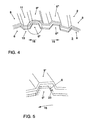
- At least one pair of corresponding Tooth and tooth gap of drive plate and clutch basket of the tooth opposite the tooth gap is displaced in the circumferential direction. At least two are preferred Teeth shifted in the opposite direction.
- the opposite to the corresponding tooth gaps shifted teeth can both on the outer circumference of the drive plate and the clutch basket located or on the outer circumference of both components.
- the shift is preferred but only on the outer periphery of a component, in particular is preferred, in each case a plurality of teeth in both directions in the circumferential direction move. As a result, the strength of the spline is increased.
- the reference numeral 1 denotes the subarea of a dual-clutch transmission represented, in which the clutch basket 2 drivingly effective with a drive plate. 3 rotatably connected.
- the drive plate 3 is in turn rotatably and drive effective on a transmission input shaft 4, which is not one of them here shown crankshaft of a drive motor is driven.
- the clutch basket 2 itself serves in a known manner as a carrier for the friction linings of the two clutches of the dual-clutch transmission.
- the clutch basket 2 can be seen, the Connection area with teeth 11 and tooth gaps 8 is provided.
- gearing 11, 8 can teeth 6 and gaps 15 of the drive plate. 3 engage in order to achieve the desired connector in the direction of the arrow 14 is to be inserted into the clutch basket 2.
- Such a targeted reduction of the flexural rigidity of the teeth 11 or tooth gaps 11 may also be performed on the clutch basket 2.
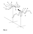
- Figure 2 is clearly removed, can alternatively or additionally in addition to the teeth 6 of the drive plate and the Teeth 11 and the tooth gaps 8 may be provided with slots 9, 10, in the field of Splines between drive plate and clutch basket to the targeted Material weakening lead.
- the tooth thickness 16 is at least one of the teeth 6 of the drive plate 3 is greater than the tooth gap 17 of the drive plate 2, so that the drive plate 3 under application of a pressing force so tight in the clutch basket can be inserted, that this to a widening of the Tooth gaps 8 in the region of the slot 9 or to a compression of the teeth 6, 11 in the region of the slots 7 and 10 leads.
- the so on the tooth flanks of the Insertion elements applied normal force leads to a torsional backlash-free Spline connection, which avoids the usual rattle noise become.
Landscapes
- Engineering & Computer Science (AREA)
- General Engineering & Computer Science (AREA)
- Mechanical Engineering (AREA)
- Mechanical Operated Clutches (AREA)
Description
- Fig. 1
- einen vertikalen Schnitt durch ein Doppelkupplungsgetriebe im Bereich des Kupplungskorbes,
- Fig. 2
- eine schematische Darstellung von Mitnehmerscheibe und Kupplungskorb vor ihrem Zusammenführen,
- Fig. 3
- eine Darstellung wie in Fig. 2, jedoch mit einer weiteren Ausführungsform der Erfindung,
- Fig. 4
- eine Darstellung von Mitnehmerscheibe und Kupplungskorb vor ihrem Zusammenführen, wobei zwei Zähne gegenüber den korrespondierenden Zahnlücken verschoben sind und
- Fig. 5
- detaillierte Darstellung eines verschobenen Zahnes.
- 1
- Doppelkupplungsgetriebe im Bereich der Doppelkupplung
- 2
- Kupplungskorb
- 3
- Mitnehmerscheibe
- 4
- Getriebeeingangswelle
- 5
- Einzelheit
- 6
- Mitnehmerscheibenzahn
- 6"
- Mitnehmerscheibenzahn (verschoben in Richtung 18)
- 6'''
- Mitnehmerscheibenzahn (verschoben in Richtung 19)
- 7
- Schlitz
- 8
- Kupplungskorbzahnlücke
- 8'
- Kupplungskorbzahnlücke
- 8"
- Kupplungskorbzahnlücke (zum Zahn 6")
- 8'''
- Kupplungskorbzahnlücke (zum Zahn 6''')
- 9
- Schlitz
- 9'
- Schlitz
- 10
- Schlitz
- 11
- Kupplungskorbzahn
- 11"
- Kupplungskorbzahn (verschoben in Richtung 18)
- 11'''
- Kupplungskorbzahn (verschoben in Richtung 19)
- 12
- Einführschräge
- 13
- Einführschräge
- 14
- Einbaurichtung
- 15
- Mitnehmerscheibenzahnlücke
- 15"
- Mitnehmerscheibenzahnlücke (zum Zahn 11")
- 15'''
- Mitnehmerscheibenzahnlücke (zum Zahn 11''')
- 16
- Zahndicke
- 17
- Zahnlückenweite
- 18
- Umfangsrichtung
- 19
- Umfangsrichtung (entgegengesetzt zu 18)
- 20
- Verschiebungslänge (zum Zahn 6")
Claims (7)
- Getriebe mit rasselfreier Verbindung zwischen Kupplungskorb (2) und Mitnehmerscheibe (3), bei der die Mitnehmerscheibe (3) an ihrem Außenumfang über Zähne (6) und Zahnlücken (15) verfügt, bei der der Kupplungskorb (2) an seinem Außenumfang zu den Zähnen (6) und Zahnlücken (15) der Mitnehmerscheibe (3) korrespondierende Zähne (11) und Zahnlücken (8) aufweist und bei der die Mitnehmerscheibe (3) im Sinne einer Steckverzahnung axial in den Kupplungskorb (2) einsteckbar ist, dadurch gekennzeichnet, daß wenigstens einer der Zähne (6) der Mitnehmerscheibe (3) und/oder wenigstens einer der Zähne (11) des Kupplungskorbes (2) axial ausgerichtete Schlitze (7, 10) aufweisen, und daß die Zahndicke (16) wenigstens einer der Zähne (6) der Mitnehmerscheibe (3) größer ist als wenigstens eine der Zahnlückenweiten (17) des Kupplungskorbes (2).
- Getriebe gemäß Anspruch 1, dadurch gekennzeichnet, daß wenigstens einer der Zahnlücken (8) des Kupplungskorbes (2) einen Schlitz (11) aufweist.
- Getriebe nach einem oder mehreren der Ansprüche 1 bis 2, dadurch gekennzeichnet, daß die Stirnseiten wenigstens einer Korbzahnlücke (9) und/oder wenigstens eines Mitnehmerscheibenzahnes (6) Einführungsschrägen (12, 13) aufweisen.
- Getriebe mit rasselfreier Verbindung zwischen Kupplungskorb (2) und Mitnehmerscheibe (3), bei der die Mitnehmerscheibe (3) an ihrem Außenumfang über Zähne (6) und Zahnlücken (15) verfügt, bei der der Kupplungskorb (2) an seinem Außenumfang zu den Zähnen (6) und Zahnlücken (15) der Mitnehmerscheibe (3) korrespondierende Zähne (11) und Zahnlücken (8) aufweist und bei der die Mitnehmerscheibe (3) im Sinne einer Steckverzahnung axial in den Kupplungskorb (2) einsteckbar ist, dadurch gekennzeichnet, daß bei mindestens einem Paar von korrespondierendem Zahn (6", 11") und Zahnlücke (8", 15"), wobei sich der Zahn an dem Außenumfang von der Mitnehmerscheibe (3) oder dem Kupplungskorb (2) befinden kann, der Zahn (6", 11") gegenüber der Zahnlücke (8", 15") in Umfangsrichtung in einer ersten Richtung (18) verschoben ist.
- Getriebe gemäß Anspruch 4, dadurch gekennzeichnet, daß bei mindestens einem weiteren Paar von korrespondierendem Zahn (6''', 11''') und Zahnlücke (8"', 15'''), wobei sich der Zahn an dem Außenumfang von der Mitnehmerscheibe (3) oder dem Kupplungskorb (2) befinden kann, der Zahn (6''', 11''') gegenüber der Zahnlücke (8''', 15''') in Umfangsrichtung in der der ersten Richtung (18) entgegengesetzten Richtung (19) verschoben ist.
- Getriebe gemäß Anspruch 5, dadurch gekennzeichnet, daß der mindestens eine gegenüber der korrespondierenden Zahnlücke (8", 15") in Umfangsrichtung in der ersten Richtung (18) verschobene Zahn (6", 11") und der mindestens eine weitere gegenüber der korrespondierenden Zahnlücke (8''', 15''') in Umfangsrichtung in der der ersten Richtung (18) entgegengesetzten Richtung (19) verschobene Zahn (6''', 11''') sich beide an dem Außenumfang von der Mitnehmerscheibe (3) oder dem Kupplungskorb (2) befinden.
- Getriebe gemäß Anspruch 6, dadurch gekennzeichnet, daß mehrere gegenüber den korrespondierenden Zahnlücken (8") des Kupplungskorbes (2) in Umfangsrichtung in der ersten Richtung (18) verschobene Zähne (6") und mehrere weitere gegenüber den korrespondierenden Zahnlücken (8''') des Kupplungskorbes (2) in Umfangsrichtung in der der ersten Richtung (18) entgegengesetzten Richtung (19) verschobene Zähne (6''') sich an dem Außenumfang von der Mitnehmerscheibe (3) befinden.
Applications Claiming Priority (3)
| Application Number | Priority Date | Filing Date | Title |
|---|---|---|---|
| DE10118233 | 2001-04-11 | ||
| DE10118233A DE10118233A1 (de) | 2001-04-11 | 2001-04-11 | Getriebe mit rasselfreier Verbindung zwischen Kupplungskorb und Mitnehmerscheibe |
| PCT/EP2002/003963 WO2002084135A1 (de) | 2001-04-11 | 2002-04-10 | Getriebe mit rasselfreier verbindung zwischen kupplungskorb und mitnehmerscheibe |
Publications (2)
| Publication Number | Publication Date |
|---|---|
| EP1381788A1 EP1381788A1 (de) | 2004-01-21 |
| EP1381788B1 true EP1381788B1 (de) | 2005-10-26 |
Family
ID=7681322
Family Applications (1)
| Application Number | Title | Priority Date | Filing Date |
|---|---|---|---|
| EP02735241A Expired - Lifetime EP1381788B1 (de) | 2001-04-11 | 2002-04-10 | Getriebe mit rasselfreier verbindung zwischen kupplungskorb und mitnehmerscheibe |
Country Status (5)
| Country | Link |
|---|---|
| US (1) | US6938747B2 (de) |
| EP (1) | EP1381788B1 (de) |
| CN (1) | CN1502016A (de) |
| DE (2) | DE10118233A1 (de) |
| WO (1) | WO2002084135A1 (de) |
Cited By (1)
| Publication number | Priority date | Publication date | Assignee | Title |
|---|---|---|---|---|
| EP1950440B2 (de) † | 2007-01-26 | 2013-11-13 | Hoerbiger Antriebstechnik GmbH | Verfahren zur Herstellung eines Kupplungskorbes einer Doppelkupplung |
Families Citing this family (16)
| Publication number | Priority date | Publication date | Assignee | Title |
|---|---|---|---|---|
| DE10133638A1 (de) † | 2001-07-11 | 2003-01-30 | Zf Sachs Ag | Mehrfach-Kupplungseinrichtung, insbesondere Doppel-Kupplungseinrichtung |
| ATE311550T1 (de) * | 2002-11-19 | 2005-12-15 | Volkswagen Ag | Kfz-getriebe mit lamellenkupplung |
| KR100569135B1 (ko) * | 2003-12-19 | 2006-04-07 | 현대자동차주식회사 | 자동 변속기의 로우 코스트 브레이크 |
| US7287632B1 (en) | 2005-03-24 | 2007-10-30 | Barnett Tool & Engineering | Vehicle clutch basket |
| US8272115B2 (en) * | 2005-04-27 | 2012-09-25 | Leif Lewis | Multi-plate clutch and method |
| US20060243555A1 (en) * | 2005-04-27 | 2006-11-02 | Leif Lewis | Multi-plate clutch |
| DE102011003824A1 (de) * | 2010-02-25 | 2011-08-25 | BorgWarner Inc., Mich. | Wellband für Kupplungsgehäuse und -nabe mit Keilverzahnung |
| US20120145508A1 (en) * | 2010-12-14 | 2012-06-14 | GM Global Technology Operations LLC | Core plate with an extruded spline |
| DE102014205064B4 (de) * | 2013-04-02 | 2025-08-14 | Schaeffler Technologies AG & Co. KG | Kupplung aufweisend einen Druckring mit Bajonettverschluss |
| DE112015000930A5 (de) * | 2014-02-24 | 2016-11-03 | Schaeffler Technologies AG & Co. KG | Kupplung mit Flanschverbindung |
| US9745074B2 (en) * | 2015-09-30 | 2017-08-29 | Brp-Powertrain Gmbh & Co Kg | Aircraft propeller drive system |
| DE102015224817B4 (de) | 2015-12-10 | 2024-11-07 | Schaeffler Technologies AG & Co. KG | Mitnehmereinheit und Kupplungseinrichtung |
| DE102015121705A1 (de) * | 2015-12-14 | 2017-06-14 | Knorr-Bremse Systeme für Nutzfahrzeuge GmbH | Kupplungsanordnung, insbesondere zum optionalen Verbinden eines Luftverdichters mit einer Antriebseinrichtung |
| DE102017207516A1 (de) * | 2017-05-04 | 2018-11-08 | Zf Friedrichshafen Ag | Steckverzahnungsanordnung |
| DE102020210871A1 (de) * | 2020-08-28 | 2022-03-03 | Zf Friedrichshafen Ag | Nasslaufende Lamellenkupplung und Kraftfahrzeug-Getriebe |
| DE102021106019A1 (de) | 2021-03-12 | 2022-09-15 | Schaeffler Technologies AG & Co. KG | Trockene Lamellenkupplung |
Family Cites Families (9)
| Publication number | Priority date | Publication date | Assignee | Title |
|---|---|---|---|---|
| US1467732A (en) * | 1921-07-13 | 1923-09-11 | Harold H Emmons | Clutch disk |
| US2335504A (en) * | 1942-11-13 | 1943-11-30 | Gazda Antoine | Gear tooth |
| US4640294A (en) * | 1985-03-01 | 1987-02-03 | Ordo Richard A | Assembly method and apparatus for spline-type connection |
| US4840294A (en) * | 1988-02-12 | 1989-06-20 | Illinois Tool Works Inc. | Adjustable dispensing tool |
| JPH0262410A (ja) * | 1988-08-29 | 1990-03-02 | Fuji Technica Inc | スプライン圧入嵌合方法 |
| GB9303487D0 (en) * | 1993-02-22 | 1993-04-07 | Yang Tai Her | Structure and device for extinguishing flexible gear lash |
| JP3385347B2 (ja) * | 1994-03-17 | 2003-03-10 | ジヤトコ株式会社 | 自動変速機の多板クラッチ・ブレーキ |
| JP3322015B2 (ja) * | 1994-08-26 | 2002-09-09 | スズキ株式会社 | 摩擦係合装置のハウジング制振構造 |
| US5924928A (en) * | 1997-06-13 | 1999-07-20 | Ford Motor Company | Engagement noise isolator for an automatic transmission |
-
2001
- 2001-04-11 DE DE10118233A patent/DE10118233A1/de not_active Withdrawn
-
2002
- 2002-04-10 DE DE50204687T patent/DE50204687D1/de not_active Expired - Lifetime
- 2002-04-10 EP EP02735241A patent/EP1381788B1/de not_active Expired - Lifetime
- 2002-04-10 WO PCT/EP2002/003963 patent/WO2002084135A1/de not_active Ceased
- 2002-04-10 CN CNA028081323A patent/CN1502016A/zh active Pending
-
2003
- 2003-10-14 US US10/685,063 patent/US6938747B2/en not_active Expired - Fee Related
Cited By (1)
| Publication number | Priority date | Publication date | Assignee | Title |
|---|---|---|---|---|
| EP1950440B2 (de) † | 2007-01-26 | 2013-11-13 | Hoerbiger Antriebstechnik GmbH | Verfahren zur Herstellung eines Kupplungskorbes einer Doppelkupplung |
Also Published As
| Publication number | Publication date |
|---|---|
| DE50204687D1 (de) | 2005-12-01 |
| US6938747B2 (en) | 2005-09-06 |
| EP1381788A1 (de) | 2004-01-21 |
| DE10118233A1 (de) | 2002-10-17 |
| WO2002084135A1 (de) | 2002-10-24 |
| CN1502016A (zh) | 2004-06-02 |
| US20040084274A1 (en) | 2004-05-06 |
Similar Documents
| Publication | Publication Date | Title |
|---|---|---|
| DE69609678T2 (de) | Synchronisiervorrichtung-Kupplung-Anordnung | |
| DE3621187C2 (de) | ||
| EP1381788A1 (de) | Getriebe mit rasselfreier verbindung zwischen kupplungskorb und mitnehmerscheibe | |
| DE3934377A1 (de) | Anti-klappervorrichtung fuer ein getriebe | |
| DE3324999C2 (de) | ||
| DE3205039A1 (de) | Kupplungsscheibe | |
| DE3347203C2 (de) | Kupplungsscheibe | |
| EP2569555A1 (de) | Planetengetriebe mit verdrehsicherung | |
| DE69206257T3 (de) | Differentialgetriebe. | |
| DE1951778U (de) | Drehzahl-uebersetzungsgetriebe. | |
| DE2922528A1 (de) | Kette | |
| EP0499163A1 (de) | Getriebekomponente mit Keilverzahnung | |
| DE19601236A1 (de) | Ausgleichsgetriebe | |
| DE102007062363A1 (de) | Schaltgetriebe | |
| EP1589244B1 (de) | Mitnehmereinheit mit axial vorgespannter Mitnehmerscheibe | |
| EP3884183B1 (de) | Differentialgetriebe für ein kraftfahrzeug | |
| DE102014205064A1 (de) | Kupplung aufweisend einen Druckring mit Bajonettverschluss | |
| DE102008022865A1 (de) | Kupplungsvorrichtung mit einer eingangsseitigen Kopplungseinrichtung und Verwendung eines Zahnrades mit zwei Teilrädern zur Ausbildung einer Steckverzahnung | |
| DE69210547T2 (de) | Zahnradhalterung für ein Getriebe | |
| DE102004007815B4 (de) | Schaltgetriebe mit Sperrsynchronisation | |
| DE102007035790A1 (de) | Sperrvorrichtung sowie Getriebe-Antriebs-Einheit | |
| WO2009007191A2 (de) | Stirnraddifferentialgetriebe | |
| DE102021107296B3 (de) | Verspanneinrichtung, Hybridmodul mit Verspanneinrichtung und Verfahren zur Montage einer Verspanneinrichtung | |
| DE102005049433A1 (de) | Axiale Steckverbindungsanordnung | |
| DE3236613C2 (de) | Einscheiben-Reibungskupplung für Kraftfahrzeuge |
Legal Events
| Date | Code | Title | Description |
|---|---|---|---|
| PUAI | Public reference made under article 153(3) epc to a published international application that has entered the european phase |
Free format text: ORIGINAL CODE: 0009012 |
|
| 17P | Request for examination filed |
Effective date: 20031111 |
|
| AK | Designated contracting states |
Kind code of ref document: A1 Designated state(s): AT BE CH CY DE DK ES FI FR GB GR IE IT LI LU MC NL PT SE TR |
|
| GRAP | Despatch of communication of intention to grant a patent |
Free format text: ORIGINAL CODE: EPIDOSNIGR1 |
|
| GRAS | Grant fee paid |
Free format text: ORIGINAL CODE: EPIDOSNIGR3 |
|
| GRAA | (expected) grant |
Free format text: ORIGINAL CODE: 0009210 |
|
| AK | Designated contracting states |
Kind code of ref document: B1 Designated state(s): DE ES FR GB IT |
|
| PG25 | Lapsed in a contracting state [announced via postgrant information from national office to epo] |
Ref country code: IT Free format text: LAPSE BECAUSE OF FAILURE TO SUBMIT A TRANSLATION OF THE DESCRIPTION OR TO PAY THE FEE WITHIN THE PRESCRIBED TIME-LIMIT;WARNING: LAPSES OF ITALIAN PATENTS WITH EFFECTIVE DATE BEFORE 2007 MAY HAVE OCCURRED AT ANY TIME BEFORE 2007. THE CORRECT EFFECTIVE DATE MAY BE DIFFERENT FROM THE ONE RECORDED. Effective date: 20051026 |
|
| REG | Reference to a national code |
Ref country code: GB Ref legal event code: FG4D Free format text: NOT ENGLISH |
|
| REF | Corresponds to: |
Ref document number: 50204687 Country of ref document: DE Date of ref document: 20051201 Kind code of ref document: P |
|
| GBT | Gb: translation of ep patent filed (gb section 77(6)(a)/1977) |
Effective date: 20051219 |
|
| PG25 | Lapsed in a contracting state [announced via postgrant information from national office to epo] |
Ref country code: ES Free format text: LAPSE BECAUSE OF FAILURE TO SUBMIT A TRANSLATION OF THE DESCRIPTION OR TO PAY THE FEE WITHIN THE PRESCRIBED TIME-LIMIT Effective date: 20060206 |
|
| ET | Fr: translation filed | ||
| PLBE | No opposition filed within time limit |
Free format text: ORIGINAL CODE: 0009261 |
|
| STAA | Information on the status of an ep patent application or granted ep patent |
Free format text: STATUS: NO OPPOSITION FILED WITHIN TIME LIMIT |
|
| 26N | No opposition filed |
Effective date: 20060727 |
|
| REG | Reference to a national code |
Ref country code: DE Ref legal event code: R084 Ref document number: 50204687 Country of ref document: DE Effective date: 20111203 |
|
| REG | Reference to a national code |
Ref country code: FR Ref legal event code: PLFP Year of fee payment: 15 |
|
| PGFP | Annual fee paid to national office [announced via postgrant information from national office to epo] |
Ref country code: GB Payment date: 20160502 Year of fee payment: 15 |
|
| PGFP | Annual fee paid to national office [announced via postgrant information from national office to epo] |
Ref country code: FR Payment date: 20160427 Year of fee payment: 15 |
|
| GBPC | Gb: european patent ceased through non-payment of renewal fee |
Effective date: 20170410 |
|
| REG | Reference to a national code |
Ref country code: FR Ref legal event code: ST Effective date: 20171229 |
|
| PG25 | Lapsed in a contracting state [announced via postgrant information from national office to epo] |
Ref country code: FR Free format text: LAPSE BECAUSE OF NON-PAYMENT OF DUE FEES Effective date: 20170502 |
|
| PG25 | Lapsed in a contracting state [announced via postgrant information from national office to epo] |
Ref country code: GB Free format text: LAPSE BECAUSE OF NON-PAYMENT OF DUE FEES Effective date: 20170410 |
|
| PGFP | Annual fee paid to national office [announced via postgrant information from national office to epo] |
Ref country code: DE Payment date: 20180430 Year of fee payment: 17 |
|
| REG | Reference to a national code |
Ref country code: DE Ref legal event code: R119 Ref document number: 50204687 Country of ref document: DE |
|
| PG25 | Lapsed in a contracting state [announced via postgrant information from national office to epo] |
Ref country code: DE Free format text: LAPSE BECAUSE OF NON-PAYMENT OF DUE FEES Effective date: 20191101 |