EP3884183B1 - Differentialgetriebe für ein kraftfahrzeug - Google Patents
Differentialgetriebe für ein kraftfahrzeug Download PDFInfo
- Publication number
- EP3884183B1 EP3884183B1 EP19801746.9A EP19801746A EP3884183B1 EP 3884183 B1 EP3884183 B1 EP 3884183B1 EP 19801746 A EP19801746 A EP 19801746A EP 3884183 B1 EP3884183 B1 EP 3884183B1
- Authority
- EP
- European Patent Office
- Prior art keywords
- differential
- drive gear
- differential housing
- circumferential surface
- final drive
- Prior art date
- Legal status (The legal status is an assumption and is not a legal conclusion. Google has not performed a legal analysis and makes no representation as to the accuracy of the status listed.)
- Active
Links
Images


Classifications
-
- F—MECHANICAL ENGINEERING; LIGHTING; HEATING; WEAPONS; BLASTING
- F16—ENGINEERING ELEMENTS AND UNITS; GENERAL MEASURES FOR PRODUCING AND MAINTAINING EFFECTIVE FUNCTIONING OF MACHINES OR INSTALLATIONS; THERMAL INSULATION IN GENERAL
- F16H—GEARING
- F16H48/00—Differential gearings
- F16H48/38—Constructional details
-
- F—MECHANICAL ENGINEERING; LIGHTING; HEATING; WEAPONS; BLASTING
- F16—ENGINEERING ELEMENTS AND UNITS; GENERAL MEASURES FOR PRODUCING AND MAINTAINING EFFECTIVE FUNCTIONING OF MACHINES OR INSTALLATIONS; THERMAL INSULATION IN GENERAL
- F16D—COUPLINGS FOR TRANSMITTING ROTATION; CLUTCHES; BRAKES
- F16D1/00—Couplings for rigidly connecting two coaxial shafts or other movable machine elements
- F16D1/06—Couplings for rigidly connecting two coaxial shafts or other movable machine elements for attachment of a member on a shaft or on a shaft-end
- F16D1/064—Couplings for rigidly connecting two coaxial shafts or other movable machine elements for attachment of a member on a shaft or on a shaft-end non-disconnectable
- F16D1/068—Couplings for rigidly connecting two coaxial shafts or other movable machine elements for attachment of a member on a shaft or on a shaft-end non-disconnectable involving gluing, welding or the like
-
- F—MECHANICAL ENGINEERING; LIGHTING; HEATING; WEAPONS; BLASTING
- F16—ENGINEERING ELEMENTS AND UNITS; GENERAL MEASURES FOR PRODUCING AND MAINTAINING EFFECTIVE FUNCTIONING OF MACHINES OR INSTALLATIONS; THERMAL INSULATION IN GENERAL
- F16D—COUPLINGS FOR TRANSMITTING ROTATION; CLUTCHES; BRAKES
- F16D1/00—Couplings for rigidly connecting two coaxial shafts or other movable machine elements
- F16D1/06—Couplings for rigidly connecting two coaxial shafts or other movable machine elements for attachment of a member on a shaft or on a shaft-end
- F16D1/08—Couplings for rigidly connecting two coaxial shafts or other movable machine elements for attachment of a member on a shaft or on a shaft-end with clamping hub; with hub and longitudinal key
- F16D1/0852—Couplings for rigidly connecting two coaxial shafts or other movable machine elements for attachment of a member on a shaft or on a shaft-end with clamping hub; with hub and longitudinal key with radial clamping between the mating surfaces of the hub and shaft
- F16D1/0858—Couplings for rigidly connecting two coaxial shafts or other movable machine elements for attachment of a member on a shaft or on a shaft-end with clamping hub; with hub and longitudinal key with radial clamping between the mating surfaces of the hub and shaft due to the elasticity of the hub (including shrink fits)
-
- F—MECHANICAL ENGINEERING; LIGHTING; HEATING; WEAPONS; BLASTING
- F16—ENGINEERING ELEMENTS AND UNITS; GENERAL MEASURES FOR PRODUCING AND MAINTAINING EFFECTIVE FUNCTIONING OF MACHINES OR INSTALLATIONS; THERMAL INSULATION IN GENERAL
- F16D—COUPLINGS FOR TRANSMITTING ROTATION; CLUTCHES; BRAKES
- F16D1/00—Couplings for rigidly connecting two coaxial shafts or other movable machine elements
- F16D1/10—Quick-acting couplings in which the parts are connected by simply bringing them together axially
- F16D1/108—Quick-acting couplings in which the parts are connected by simply bringing them together axially having retaining means rotating with the coupling and acting by interengaging parts, i.e. positive coupling
- F16D1/116—Quick-acting couplings in which the parts are connected by simply bringing them together axially having retaining means rotating with the coupling and acting by interengaging parts, i.e. positive coupling the interengaging parts including a continuous or interrupted circumferential groove in the surface of one of the coupling parts
-
- F—MECHANICAL ENGINEERING; LIGHTING; HEATING; WEAPONS; BLASTING
- F16—ENGINEERING ELEMENTS AND UNITS; GENERAL MEASURES FOR PRODUCING AND MAINTAINING EFFECTIVE FUNCTIONING OF MACHINES OR INSTALLATIONS; THERMAL INSULATION IN GENERAL
- F16H—GEARING
- F16H48/00—Differential gearings
- F16H48/38—Constructional details
- F16H48/40—Constructional details characterised by features of the rotating cases
-
- F—MECHANICAL ENGINEERING; LIGHTING; HEATING; WEAPONS; BLASTING
- F16—ENGINEERING ELEMENTS AND UNITS; GENERAL MEASURES FOR PRODUCING AND MAINTAINING EFFECTIVE FUNCTIONING OF MACHINES OR INSTALLATIONS; THERMAL INSULATION IN GENERAL
- F16D—COUPLINGS FOR TRANSMITTING ROTATION; CLUTCHES; BRAKES
- F16D1/00—Couplings for rigidly connecting two coaxial shafts or other movable machine elements
- F16D1/10—Quick-acting couplings in which the parts are connected by simply bringing them together axially
- F16D2001/103—Quick-acting couplings in which the parts are connected by simply bringing them together axially the torque is transmitted via splined connections
-
- F—MECHANICAL ENGINEERING; LIGHTING; HEATING; WEAPONS; BLASTING
- F16—ENGINEERING ELEMENTS AND UNITS; GENERAL MEASURES FOR PRODUCING AND MAINTAINING EFFECTIVE FUNCTIONING OF MACHINES OR INSTALLATIONS; THERMAL INSULATION IN GENERAL
- F16H—GEARING
- F16H48/00—Differential gearings
- F16H48/38—Constructional details
- F16H2048/382—Methods for manufacturing differential gearings
-
- F—MECHANICAL ENGINEERING; LIGHTING; HEATING; WEAPONS; BLASTING
- F16—ENGINEERING ELEMENTS AND UNITS; GENERAL MEASURES FOR PRODUCING AND MAINTAINING EFFECTIVE FUNCTIONING OF MACHINES OR INSTALLATIONS; THERMAL INSULATION IN GENERAL
- F16H—GEARING
- F16H48/00—Differential gearings
- F16H48/38—Constructional details
- F16H2048/385—Constructional details of the ring or crown gear
Definitions
- the invention relates to a differential gear for a motor vehicle according to the type specified in the preamble of patent claim 1.
- the DE 10 2011 087 579 A1 discloses a spur gear differential for a drive train of a motor vehicle, with a planet carrier in which two sun gears, each with an external toothing, are arranged, which mesh with a differential gear designed as a planet gear, the two planet gears being in positive engagement with one another, and also an axle drive gear arranged substantially radially outside the planet carrier.
- a torque-transmitting connection is present, which is designed as a material and/or form-fitting and/or force-fitting connection and/or as a press fit and/or as a caulked connection and/or as a welded connection.
- the invention is based on the object of developing a differential gear according to the type specified in the preamble of patent claim 1 in such a way that the undesirable displacement of the teeth is prevented and thus the risk of the occurrence of acoustic abnormalities during operation is reduced.
- the differential gear comprises a rotatably mounted differential housing and an axle output gear which is mounted on the differential housing in a rotationally fixed manner and has external teeth, which in turn meshes with an associated drive shaft and is driven via its external teeth.
- the differential housing has two mating surfaces on its outer peripheral surface and the axle driven gear has two corresponding, radially opposite mating surfaces on its inner peripheral surface.
- the mating surfaces on the differential housing and the axle driven gear are designed as circumferential mating surfaces.
- the mating surfaces on the outer peripheral surface of the Differential housing and the mating surfaces formed on the inner circumferential surface of the axle driven gear are each designed as separate mating surfaces viewed in the axial direction, arranged geometrically apart from one another at a distance A, and the axle driven gear is pressed onto the differential housing, so that the axle driven gear and the differential housing are connected to one another by means of a first press fit and a separate second press fit axially spaced apart at a distance A.
- the two separate press fits which are axially spaced at a distance A, provide an extremely tilt-resistant bearing. This ensures that all forces resulting from the gearing can be absorbed by the tilt-resistant bearing. The tendency to tilt is thus significantly reduced, with the consequence that optimal tooth contact and thus a uniform transmission of movement that does not cause any unwanted noise is ensured.
- both the mating surfaces formed on the outer circumferential surface of the differential housing and the mating surfaces formed on the inner circumferential surface of the axle drive gear are separated from one another in the axial direction by a circumferential groove made in the respective circumferential surface, the grooves each having a length corresponding to the distance A when viewed in the axial direction.
- the groove ensures an easy-to-produce, effective geometric separation of the mating surfaces and thus the press fit.
- a further advantage is that the material removal caused by the groove has a positive effect on the component weight, so that a particularly weight-optimized design is possible. By dimensioning the groove depth accordingly, it is easy to influence the material removal and thus the weight saving.
- the grooves have a rectangular, triangular or semicircular basic shape.
- the differential gear according to the invention is characterized in that the two press fits have a small radial overlap of 10 to 50 ⁇ m and that an additional positive connection is formed between the axle drive gear and the differential housing.
- the advantage of this is that the two components are easy to join due to the relatively small radial overlap and, in addition, a high torque transmission is ensured due to the additional positive connection.
- the additional connection is designed in the form of a polygonal or splined toothing, with a locking element preventing relative movement in the axial direction being arranged between the axle drive gear and the differential housing.
- the securing element is designed in the form of a securing ring, in particular in the form of a wedge-shaped securing ring.
- the differential housing is made of cast iron and the axle output gear is made of a hardenable material.
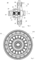
- Fig. 1 and 2 show an embodiment according to the invention of a differential gear of a motor vehicle, designated overall by the reference number 10.
- the differential gear 10 comprises a differential housing 12 and an axle driven gear 14 which is connected in a rotationally fixed manner to the differential housing 12.
- the axle driven gear 14 is connected via its external toothing 14-1 to a - here made of For reasons of clarity - drive shaft not shown in operative connection.
- the differential housing 12 drives four planetary gears 18, which in turn mesh with two output gears 20, which can be connected in a rotationally fixed manner to wheel shaft axes (not shown here for reasons of clarity).
- the differential housing 12 has two fitting surfaces on its outer peripheral surface and the axle driven gear 14 has two radially opposite fitting surfaces on its inner peripheral surface, which are each designed as separate fitting surfaces viewed in the axial direction a and arranged geometrically separated from one another at a distance A, so that the axle driven gear 14 pressed onto the differential housing 12 is connected to one another by means of a first press fit 22-1 and a separate second press fit 22-2 axially spaced apart at a distance A.
- the distance A must be selected such that: 0,5 ⁇ A / L ⁇ 0,7 , where L denotes the axial length of the inner circumferential surface of the axle drive gear 14 viewed in the axial direction a.
- a groove 24 is milled into the peripheral surface of the differential housing 12 and into the peripheral surface of the axle drive gear 14.
- the grooves 24 also result in a particularly advantageous weight reduction.
- the grooves 24 each have a substantially rectangular basic shape.
- an extremely tilt-resistant bearing is provided which can absorb all axial forces resulting from the meshing of the external toothing 14-1 of the axle output gear 14 with a drive shaft (not shown here), so that optimal tooth contact and thus a uniform transmission of motion that does not cause any undesirable noise is ensured.
- the two press fits 22-1 and 22-2 have a radial overlap of 10 to 50 ⁇ m.
- an additional positive connection is formed between the axle drive gear 14 and the differential housing 12 in the area of the first press fit 22-1. Axial securing is ensured by a locking ring 26.
- the positive connection is designed in the form of a polygonal toothing 28.
- the in Fig. 3 and 4 The first comparative form not covered by the invention shown in Fig. 1 and 2
- This comparative form differs from the embodiment according to the invention in that the additional connection between the axle drive gear 14 and the differential housing 12, which serves to transmit torque, is designed in the form of a welded connection 30.
- the welded connection 30 is designed as a one-sided, circumferential weld seam layer arranged only in the area of the first press fit 22-1. In addition to the torque transmission, the weld seam also ensures axial fixation.
- the in Fig. 5 and 6 The comparative form shown, which is not covered by the invention, is distinguished from the embodiment according to the invention in that instead of a positive connection, only a force-locking connection is now provided for the torque transmission.
- the two press fits 22-1, 22-2 have a radial overlap of >200 ⁇ m.
Landscapes
- Engineering & Computer Science (AREA)
- General Engineering & Computer Science (AREA)
- Mechanical Engineering (AREA)
- Retarders (AREA)
Description
- Die Erfindung betrifft ein Differentialgetriebe für ein Kraftfahrzeug gemäß der im Oberbegriff des Patentanspruches 1 angegebenen Art.
- Differentialgetriebe sowie unterschiedliche Konzepte zur Lagerung des Achsabtriebsrads am Differentialgehäuse sind aus dem Stand der Technik hinreichend bekannt. Lediglich beispielhaft wird auf die
EP 2 740 562 B1 ,DE 10 2017 006 417 A1 undDE 10 2016 218 087 A1 verwiesen. Insbesondere die über die Verzahnung des Achsabtriebsrads eingebrachten Axialkräfte können zu einem "Verkippen" und damit zu einer Verlagerung der Verzahnung führen, was wiederum einen ungünstigeren Zahnkontakt und damit eine ungleichmäßige Bewegungsübertragung (Drehzahl, Drehmoment) bedingt. Die ungleichmäßige Bewegungsübertragung hat akustische Auffälligkeiten zur Folge, was wiederum Anlass für Fahrzeugbeanstandungen sein kann. Insbesondere in Hinblick auf neue, einen Elektroantrieb aufweisende Fahrzeugkonzepte, gewinnen diese akustischen Beanstandungen immer mehr an Gewichtung. - Die
DE 10 2011 087 579 A1 offenbart ein Stirnraddifferenzial für einen Antriebsstrang eines Kraftfahrzeuges, mit einem Planetenträger, in dem zwei je eine Außenverzahnung aufweisende Sonnenräder angeordnet sind, die mit je einem als Planetenrad ausgebildeten Ausgleichsrad kämmen, wobei die beiden Planetenräder miteinander in Formschluss befindlich sind, und ferner ein mit einem im Wesentlichen radial außerhalb des Planetenträgers angeordnetes Achsantriebsrad vorhanden ist. Zwischen einer Innenfläche des Achsantriebsrades und einer radialen Umfangsfläche des Planetenträgers ist eine drehmomentübertragende Verbindung vorhanden, die als stoff- und/oder form- und/oder kraftschlüssige Verbindung und/oder als Pressverband und/oder als verstemmter Verband und/oder als Schweißverbindung ausgestaltet ist. - Aus der
US 2017 / 0 219 077 A1 ist ein gattungsgemäßes Differential für ein Kraftfahrzeug mit den Merkmalen des Oberbegriffs des Anspruchs 1 bekannt. - Der Erfindung liegt die Aufgabe zugrunde ein Differentialgetriebe gemäß der im Oberbegriff des Patentanspruches 1 angegebenen Art derart weiterzubilden, dass die unerwünschte Verlagerung der Verzahnung verhindert und damit die Gefahr des Auftretens von akustischen Auffälligkeiten im Betrieb verringert wird.
- Diese Aufgabe wird durch die kennzeichnenden Merkmale des Patentanspruches 1 in Verbindung mit seinen Oberbegriffsmerkmalen gelöst.
- Die Unteransprüche bilden vorteilhafte Weiterbildungen der Erfindung.
- In bekannter Art und Weise umfasst das Differentialgetriebe ein drehbar gelagertes Differentialgehäuse sowie ein drehfest auf dem Differentialgehäuse gelagertes, eine Außenverzahnung aufweisendes Achsabtriebsrad, das seinerseits über seine Außenverzahnung mit einer zugeordneten Antriebswelle kämmt und angetrieben wird.
- Zudem weist das Differentialgehäuse an seiner äußeren Umfangsfläche zwei Passflächen und das Achsabtriebsrad an seiner inneren Umfangsfläche zwei entsprechende, radial gegenüberliegende Passflächen aufweist. Lediglich der Vollständigkeit halber sei darauf hingewiesen, dass die am Differentialgehäuse und die am Achsabtriebsrad ausgebildeten Passflächen als umlaufende Passflächen ausgebildet sind. Die an der äußeren Umfangsfläche des Differentialgehäuses und die an der inneren Umfangsfläche des Achsabtriebsrads ausgebildeten Passflächen sind dabei jeweils als in axialer Richtung betrachtet separate, in einem Abstand A geometrisch voneinander getrennt angeordnete Passflächen ausgebildet und das Achsabtriebsrad ist auf das Differentialgehäuse aufgepresst, so dass das Achsabtriebsrad und das Differentialgehäuse mittels einer ersten Presspassung und einer davon separaten, im Abstand A axial beabstandeten zweiten Presspassung miteinander verbunden sind.
- Aufgrund der beiden separaten, im Abstand A axial beabstandeten Presspassungen ist eine äußerst kippsteife Lagerung zur Verfügung gestellt. Hierdurch ist gewährleistet, dass sämtliche aus der Verzahnung resultierenden Kräfte mittels der kippsteifen Lagerung aufgenommen werden können. Die Kippneigung ist dadurch deutlich reduziert, mit der Konsequenz, dass ein optimaler Zahnkontakt und damit eine gleichmäßige, keine unerwünschten Störgeräusche verursachende Bewegungsübertragung sichergestellt ist.
- Erfindungsgemäß sind dabei in axialer Richtung betrachtet sowohl die an der äußeren Umfangsfläche des Differentialgehäuses ausgebildeten Passflächen als auch die an der inneren Umfangsfläche des Achsabtriebsrads ausgebildeten Passflächen jeweils durch eine in die jeweilige Umfangsfläche eingebrachte, umlaufende Nut voneinander getrennt, wobei die Nuten in axialer Richtung betrachtet jeweils eine dem Abstand A entsprechende Länge aufweisen. Durch die Nut ist eine einfach herzustellende, wirksame geometrische Trennung der Passflächen und damit der Presspassung sichergestellt. Ein weiterer Vorteil ist, dass der durch die Nut bedingte Materialabtrag sich positiv auf das Bauteilgewicht auswirkt, so dass eine besonders gewichtsoptimierte Konstruktion ermöglicht ist. Durch eine entsprechende Dimensionierung der Nuttiefe kann auf einfache Art und Weise Einfluss auf den Materialabtrag und damit auf die Gewichtseinsparung genommen werden.
- Bevorzugt weisen dabei die Nuten eine rechteckige, dreiecksförmige oder halbrunde Grundform auf.
- Um eine ausreichend kippsteife Lagerung gewährleisten zu können, sollte der Abstand A zwischen den Passflächen möglichst groß sein. Erste Versuche haben gezeigt, dass der gewünschte Effekt, nämlich die kippsteife Lagerung gewährleistet ist, wenn

- Das erfindungsgemäße Differentialgetriebe zeichnet sich dadurch aus, dass die beiden Presspassungen eine geringe radiale Überdeckung von 10 bis 50µm aufweisen und dass zwischen dem Achsabtriebsrad und Differentialgehäuse eine zusätzliche formschlüssige Verbindung ausgebildet ist. Vorteilhaft daran ist, dass aufgrund der relativ geringen radialen Überdeckung die beiden Bauteile einfach zu fügen sind und zudem - aufgrund der zusätzlichen form schlüssigen Verbindung - eine hohe Drehmomentübertragung sichergestellt ist.
- Erfindungsgemäß ist die zusätzliche Verbindung in Form einer Polygon- oder Passverzahnung ausgebildet, wobei zwischen Achsabtriebsrad und Differentialgehäuse ein eine Relativbewegung in axiale Richtung verhinderndes Sicherungselement angeordnet ist. Vorteilhaft an dieser Ausgestaltung ist, dass diese aufgrund der formschlüssigen Verbindung ein im Vergleich zu einer stoffschlüssigen Verbindung geringes Bauteilgewicht aufweist.
- Vorzugsweise ist dabei das Sicherungselement in Form eines Sicherungsrings, insbesondere in Form eines keilförmigen Sicherungsrings, ausgebildet.
- Vorzugsweise ist das Differentialgehäuse aus Gusseisen und das Achsabtriebsrad aus einem härtbaren Werkstoff hergestellt.
- Weitere Vorteile und Anwendungsmöglichkeiten der vorliegenden Erfindung ergeben sich aus der nachfolgenden Beschreibung in Verbindung mit dem in der Zeichnung dargestellten Ausführungsbeispiel.
- In der Zeichnung bedeutet:
- Fig. 1
- eine Schnittdarstellung einer erfindungsgemäßen Ausführungsform eines erfindungsgemäßen Differentialgetriebes;
- Fig. 2
- das Differentialgetriebe aus
Fig. 1 in der Draufsicht; - Fig. 3
- eine nicht von der Erfindung umfasste erste Vergleichsform in Schnittdarstellung;
- Fig. 4
- das Differentialgetriebe aus
Fig. 3 in der Draufsicht; - Fig. 5
- eine Schnittdarstellung einer nicht von der Erfindung umfassten zweiten Vergleichsform, und
- Fig. 6
- das Differentialgetriebe aus
Fig. 5 in der Draufsicht. - In der nachfolgenden Beschreibung und in den Figuren werden zur Vermeidung von Wiederholungen gleiche Bauteile und Komponenten mit gleichen Bezugszeichen gekennzeichnet, sofern keine weitere Differenzierung erforderlich oder sinnvoll ist.
-
Fig. 1 und 2 zeigen eine erfindungsgemäße Ausführungsform eines insgesamt mit der Bezugsziffer 10 bezeichneten Differentialgetriebes eines Kraftfahrzeugs. - Das Differentialgetriebe 10 umfasst ein Differentialgehäuse 12 und ein mit dem Differentialgehäuse 12 drehfest verbundenes Achsabtriebsrad 14. Das Achsabtriebsrad 14 steht über seine Außenverzahnung 14-1 mit einer - hier aus Gründen der Übersichtlichkeit - nicht dargestellten Antriebswelle in Wirkverbindung.
- Über einen kreuzförmigen Mitnahmebolzen 16 treibt das Differentialgehäuse 12 vier Planentenräder 18 an, die wiederum mit zwei Abtriebsrädern 20 kämmen, welche mit - hier aus Gründen der Übersichtlichkeit nicht dargestellten - Radwellenachsen drehfest verbindbar sind.
- Wie
Fig. 1 und 2 zu entnehmen ist, weist das Differentialgehäuse 12 an seiner äußeren Umfangsfläche zwei Passflächen und das Achsabtriebsrad 14 an seiner inneren Umfangsfläche zwei radial gegenüberliegende Passflächen auf, die jeweils als in axialer Richtung a betrachtet separate, in einem Abstand A geometrisch voneinander getrennt angeordnete Passflächen ausgebildet sind, so dass das auf das Differentialgehäuse 12 aufgepresste Achsabtriebsrad 14 mittels einer ersten Presspassung 22-1 und einer davon separaten, im Abstand A axial beabstandeten zweiten Presspassung 22-2 miteinander verbunden ist. - Um eine für die kippsteife Lagerung ausreichenden Beabstandung zwischen den Presspassungen 22-1 und 22-2 zu gewährleisten, ist der Abstand A so zu wählen, dass gilt:

- Zur geometrischen Trennung der Passflächen und damit der ersten und zweiten Presspassung 22-1, 22-2 ist - wie
Fig. 1 weiter zu entnehmen ist - in die Umfangsfläche des Differentialgehäuses 12 und in die Umfangsfläche des Achsabtriebrads 14 jeweils eine Nut 24 eingefräst. Neben der geometrischen Trennung, ist durch die Nuten 24 in besonders vorteilhafter Weise insbesondere auch eine Gewichtsreduzierung bedingt. - Vorliegend weisen die eingebrachten Nuten 24 jeweils eine im Wesentlichen reckteckförmige Grundform auf.
- Aufgrund der in axialer Richtung a beabstandeten Anordnung der beiden Presspassungen 22-1, 22-2 ist eine äußerst kippsteife Lagerung zur Verfügung gestellt, die sämtliche aus der Kämmung der Außenverzahnung 14-1 des Achsabtriebsrads 14 mit einer - hier nicht dargestellten Antriebswelle - resultierenden Axialkräfte aufnehmen kann, so dass ein optimaler Zahnkontakt und damit eine gleichmäßige, keine unerwünschte Störgeräusche verursachende Bewegungsübertragung sichergestellt ist.
- Gemäß der in
Fig. 1 und Fig. 2 dargestellten Ausführungsform weisen die beiden Presspassungen 22-1 und 22-2 eine radiale Überdeckung von 10 bis 50µm auf. Zur Gewährleistung der Drehmomentübertragung ist zudem zwischen Achsabtriebsrad 14 und Differentialgehäuse 12 im Bereich der ersten Presspassung 22-1 eine zusätzliche formschlüssige Verbindung ausgebildet. Die axiale Sicherung ist über einen Sicherungsring 26 gewährleistet. - Wie insbesondere aus
Fig. 2 ersichtlich, ist dabei vorliegend die formschlüssige Verbindung in Form einer Polygonverzahnung 28 ausgebildet. - Die in
Fig. 3 und 4 dargestellte nicht von der Erfindung umfasste erste Vergleichsform entspricht im Wesentlichen der inFig. 1 und 2 dargestellten erfindungsgemäßen Ausführungsform. Gegenüber der erfindungsgemäßen Ausführungsform unterscheidet sich diese Vergleichsform dadurch, dass die zusätzliche, der Drehmomentübertragung dienende Verbindung zwischen Achsabtriebsrad 14 und Differentialgehäuse 12 in Form einer Schweißverbindung 30 ausgebildet ist. Dabei ist - wie insbesondereFig. 3 und 4 zeigen - die Schweißverbindung 30 als eine einseitige, lediglich im Bereich der ersten Presspassung 22-1 angeordnete umlaufende Schweißnahtlage ausgebildet. Neben der Drehmomentübertragung ist durch die Schweißnaht auch eine axiale Fixierung sichergestellt. - Die in
Fig. 5 und 6 dargestellte nicht von der Erfindung umfasste Vergleichsform zeichnet sich gegenüber der erfindungsgemäßen Ausführungsform dadurch aus, dass für die Drehmomentübertragung anstelle einer formschlüssigen Verbindung nunmehr ausschließlich eine kraftschlüssige Verbindung vorgesehen ist. Um eine ausreichende Drehmomentübertragung sicherzustellen, weisen hierbei die beiden Presspassungen 22-1, 22-2 eine radiale Überdeckung von >200µm auf.
Claims (5)
- Differentialgetriebe (10), umfassend ein drehbar gelagertes Differentialgehäuse (12) und ein drehfest mit dem Differentialgehäuse (12) gelagertes Achsabtriebsrad (14), wobeidas Differentialgehäuse (12) an seiner äußeren Umfangsfläche zwei Passflächen und das Achsabtriebsrad (14) an seiner inneren Umfangsfläche zwei radial gegenüberliegende Passflächen aufweist, wobei die an der äußeren Umfangsfläche des Differentialgehäuses (12) und die an der inneren Umfangsfläche des Achsabtriebsrads (14) ausgebildeten Passflächen jeweils als in axialer Richtung (a) betrachtet separate, in einem Abstand (A) geometrisch voneinander getrennt angeordnete Passflächen ausgebildet sind, und dass das Achsabtriebsrad (14) auf das Differentialgehäuse (12) aufgepresst ist, so dass das Achsabtriebsrad (14) und das Differentialgehäuse (12) mittels einer ersten Presspassung (22-1) und einer davon separaten, im Abstand (A) axial beabstandeten zweiten Presspassung (22-2) miteinander verbunden sind,dadurch gekennzeichnet, dassdie an der äußeren Umfangsfläche des Differentialgehäuses (12) ausgebildeten Passflächen und die an der inneren Umfangsfläche des Achsabtriebsrads (14) ausgebildeten Passflächen in axialer Richtung (a) jeweils durch eine in die jeweilige Umfangsfläche eingebrachte umlaufende Nut (24) voneinander getrennt sind, wobei die Nuten (24) in axialer Richtung (a) betrachtet jeweils eine dem Abstand (A) entsprechende Länge aufweisen, dass die beiden Presspassungen (22-1, 22-2) eine radiale Überdeckung von 10 bis 50µm aufweisen dass zwischen Achsabtriebsrad (14) und Differentialgehäuse (12) eine zusätzliche formschlüssige Verbindung ausgebildet ist, und dass die zusätzliche Verbindung in Form einer Polygon- oder Passverzahnung (28) ausgebildet ist, und dass zwischen Achsabtriebsrad (14) und Differentialgehäuse (12) ein eine Relativbewegung in axiale Richtung (a) verhinderndes Sicherungselement (26) angeordnet ist.
- Differentialgetriebe (10) nach Anspruch 1,
dadurch gekennzeichnet, dass
die Nuten (24) eine rechteckige, dreiecksförmige oder halbrunde Grundform aufweisen. - Differentialgetriebe (10) nach einem der Ansprüche 1 oder 2,
dadurch gekennzeichnet, dass
in axialer Richtung (a) betrachtet die innere Umfangsfläche des Achsabtriebsrads (14) eine Länge (L) aufweist, und dass bezogen auf die Länge (L) der inneren Umfangsfläche für den Abstand (A) zwischen den Passflächen gilt:
- Differentialgetriebe (10) nach einem der vorhergehenden Ansprüche,
dadurch gekennzeichnet, dass
das Sicherungselement (26) in Form eines Sicherungsrings ausgebildet ist. - Differentialgetriebe (10) nach einem der vorgenannten Ansprüche,
dadurch gekennzeichnet, dass
das Differentialgehäuse (12) aus Gusseisen und das Achsabtriebsrad (14) aus einem härtbaren Werkstoff ausgebildet ist.
Applications Claiming Priority (2)
| Application Number | Priority Date | Filing Date | Title |
|---|---|---|---|
| DE102018220105.6A DE102018220105B4 (de) | 2018-11-22 | 2018-11-22 | Differentialgetriebe für ein Kraftfahrzeug mit einem durch zwei Presspassungen am Gehäuse aufgepressten Abtriebsrad |
| PCT/EP2019/079789 WO2020104165A1 (de) | 2018-11-22 | 2019-10-31 | Differentialgetriebe für ein kraftfahrzeug |
Publications (2)
| Publication Number | Publication Date |
|---|---|
| EP3884183A1 EP3884183A1 (de) | 2021-09-29 |
| EP3884183B1 true EP3884183B1 (de) | 2025-02-26 |
Family
ID=68536791
Family Applications (1)
| Application Number | Title | Priority Date | Filing Date |
|---|---|---|---|
| EP19801746.9A Active EP3884183B1 (de) | 2018-11-22 | 2019-10-31 | Differentialgetriebe für ein kraftfahrzeug |
Country Status (5)
| Country | Link |
|---|---|
| US (1) | US11353100B2 (de) |
| EP (1) | EP3884183B1 (de) |
| CN (1) | CN113167366B (de) |
| DE (1) | DE102018220105B4 (de) |
| WO (1) | WO2020104165A1 (de) |
Families Citing this family (2)
| Publication number | Priority date | Publication date | Assignee | Title |
|---|---|---|---|---|
| CN215409689U (zh) * | 2021-08-02 | 2022-01-04 | 博世汽车转向系统(济南)有限公司 | 用于转向机的螺母部件和转向机 |
| DE102022127223B4 (de) * | 2022-10-18 | 2024-10-10 | Dr. Ing. H.C. F. Porsche Aktiengesellschaft | Differentialgetriebe für ein Kraftfahrzeug mit einem durch eine Schweißnaht mit Entlastungsnut an einem Käfig angeordneten Zahnrad |
Citations (5)
| Publication number | Priority date | Publication date | Assignee | Title |
|---|---|---|---|---|
| US20050090358A1 (en) * | 2003-10-27 | 2005-04-28 | Phelan Perry E. | Planetary differential |
| DE102011080002A1 (de) * | 2011-07-28 | 2013-01-31 | Schaeffler Technologies AG & Co. KG | Stirnraddifferenzial |
| WO2014086353A1 (de) * | 2012-12-04 | 2014-06-12 | Schaeffler Technologies AG & Co. KG | Stirnraddifferentialgetriebe |
| US20160377161A1 (en) * | 2014-01-16 | 2016-12-29 | Audi Ag | Differential gear assembly |
| US20170219077A1 (en) * | 2011-09-06 | 2017-08-03 | Eaton Corporation | Compact planetary differential gear set arrangement |
Family Cites Families (16)
| Publication number | Priority date | Publication date | Assignee | Title |
|---|---|---|---|---|
| JP3589863B2 (ja) * | 1997-07-23 | 2004-11-17 | 株式会社日立製作所 | 構造体および摩擦攪拌接合方法 |
| FR2805482B1 (fr) * | 2000-02-25 | 2002-05-03 | Renault | Piece mecanique de transmission |
| DE10030901A1 (de) * | 2000-06-23 | 2002-01-03 | Zahnradfabrik Friedrichshafen | Differential |
| DE102008057370A1 (de) | 2008-11-14 | 2010-05-20 | Bayerische Motoren Werke Aktiengesellschaft | Hinterachsgetriebe für ein Fahrzeug |
| JP5399206B2 (ja) * | 2009-11-04 | 2014-01-29 | マツダ株式会社 | 金属部材の接合方法および金属接合体 |
| KR101344562B1 (ko) * | 2010-01-22 | 2013-12-26 | 도요타지도샤가부시키가이샤 | 용접 구조 및 용접 방법 |
| EP2573426B1 (de) * | 2010-05-18 | 2014-12-03 | Toyota Jidosha Kabushiki Kaisha | Befestigungsstruktur für einen zahnkranz |
| WO2011158330A1 (ja) * | 2010-06-15 | 2011-12-22 | トヨタ自動車株式会社 | リングギアとデフケースの溶接構造 |
| KR101403824B1 (ko) * | 2011-08-04 | 2014-06-03 | 도요타지도샤가부시키가이샤 | 용접 구조 및 용접 구조의 제조 방법 |
| JP2013096550A (ja) * | 2011-11-04 | 2013-05-20 | Nabtesco Corp | 歯車伝動装置 |
| DE102011087579A1 (de) * | 2011-12-01 | 2013-06-06 | Schaeffler Technologies AG & Co. KG | Stirnraddifferenzial mit auf Trägerteil zentriertem Antriebsrad |
| DE102013219445A1 (de) * | 2013-09-26 | 2015-03-26 | Siemens Aktiengesellschaft | Zahnradherstellungsverfahren |
| JP6501584B2 (ja) * | 2015-03-30 | 2019-04-17 | 武蔵精密工業株式会社 | 伝動装置 |
| WO2017050375A1 (en) | 2015-09-23 | 2017-03-30 | Gkn Driveline Köping Ab | Connecting assembly and method for producing a connecting assembly |
| JP6196271B2 (ja) * | 2015-09-25 | 2017-09-13 | 株式会社Subaru | 溶接構造及び溶接構造の製造方法 |
| JP6335983B2 (ja) | 2016-08-08 | 2018-05-30 | 株式会社Subaru | 差動装置の製造方法及び差動装置 |
-
2018
- 2018-11-22 DE DE102018220105.6A patent/DE102018220105B4/de active Active
-
2019
- 2019-10-31 WO PCT/EP2019/079789 patent/WO2020104165A1/de not_active Ceased
- 2019-10-31 US US17/286,136 patent/US11353100B2/en active Active
- 2019-10-31 CN CN201980076503.8A patent/CN113167366B/zh active Active
- 2019-10-31 EP EP19801746.9A patent/EP3884183B1/de active Active
Patent Citations (5)
| Publication number | Priority date | Publication date | Assignee | Title |
|---|---|---|---|---|
| US20050090358A1 (en) * | 2003-10-27 | 2005-04-28 | Phelan Perry E. | Planetary differential |
| DE102011080002A1 (de) * | 2011-07-28 | 2013-01-31 | Schaeffler Technologies AG & Co. KG | Stirnraddifferenzial |
| US20170219077A1 (en) * | 2011-09-06 | 2017-08-03 | Eaton Corporation | Compact planetary differential gear set arrangement |
| WO2014086353A1 (de) * | 2012-12-04 | 2014-06-12 | Schaeffler Technologies AG & Co. KG | Stirnraddifferentialgetriebe |
| US20160377161A1 (en) * | 2014-01-16 | 2016-12-29 | Audi Ag | Differential gear assembly |
Also Published As
| Publication number | Publication date |
|---|---|
| US20210356028A1 (en) | 2021-11-18 |
| DE102018220105B4 (de) | 2021-01-21 |
| CN113167366B (zh) | 2024-12-20 |
| US11353100B2 (en) | 2022-06-07 |
| CN113167366A (zh) | 2021-07-23 |
| DE102018220105A1 (de) | 2020-05-28 |
| EP3884183A1 (de) | 2021-09-29 |
| WO2020104165A1 (de) | 2020-05-28 |
Similar Documents
| Publication | Publication Date | Title |
|---|---|---|
| DE3006331C2 (de) | Getriebe | |
| DE69108688T2 (de) | Ausgleichsgetriebeeinheit mit schwimmenden Tellerrad. | |
| DE3934377A1 (de) | Anti-klappervorrichtung fuer ein getriebe | |
| EP1298353B1 (de) | Zahnradpaarung und deren Verwendung | |
| DE19547980A1 (de) | Differentialgetriebe | |
| EP3884183B1 (de) | Differentialgetriebe für ein kraftfahrzeug | |
| WO2008110425A2 (de) | Stirnraddifferenzial mit überlagerungsdifferenzial | |
| DE102021003333B3 (de) | Getriebevorrichtung mit einer Welle | |
| DE10308800A1 (de) | Kronenraddifferential bzw. Satz von zumindest zwei Kronenraddifferentialen | |
| DE102019205608B4 (de) | Parksperrenrad | |
| DE112018002557T5 (de) | Kompaktes Platenrad-Differential | |
| EP4229310B1 (de) | Welle-nabe-verbindung mit einer steckverzahnung | |
| DE102009027342A1 (de) | Überlagerungsgetriebe für ein Lenksystem | |
| DE102023206760B4 (de) | Wellenkupplung | |
| EP1191256A2 (de) | Anlasserrad für ein Kraftfahrzeug oder dergleichen | |
| DE4329404B4 (de) | Zweiteiliges Zahnrad zur Reduzierung von Zahneingriffsgeräuschen | |
| WO2010105877A1 (de) | Schaltgetriebe | |
| DE102023210998B3 (de) | Getriebeanordnung für ein Fahrzeug | |
| DE102017207047B4 (de) | Antriebsstrang für ein Kraftfahrzeug, Planetenraddifferential für einen Antriebsstrang und Kraftfahrzeug mit einem Antriebsstrang | |
| DE102020109755A1 (de) | Spannungswellengetriebe | |
| DE102006036732B4 (de) | Gelenkbeschlag für eine Verstellvorrichtung eines Kraftfahrzeugsitzes | |
| DE202006020107U1 (de) | Antriebsanordnung mit Toleranzring | |
| AT525577B1 (de) | Planetengetriebe | |
| DE102018221419A1 (de) | Getriebe | |
| DE202024101583U1 (de) | Stützanordnung für einen radseitigen Untersetzungsantrieb |
Legal Events
| Date | Code | Title | Description |
|---|---|---|---|
| STAA | Information on the status of an ep patent application or granted ep patent |
Free format text: STATUS: UNKNOWN |
|
| STAA | Information on the status of an ep patent application or granted ep patent |
Free format text: STATUS: THE INTERNATIONAL PUBLICATION HAS BEEN MADE |
|
| PUAI | Public reference made under article 153(3) epc to a published international application that has entered the european phase |
Free format text: ORIGINAL CODE: 0009012 |
|
| STAA | Information on the status of an ep patent application or granted ep patent |
Free format text: STATUS: REQUEST FOR EXAMINATION WAS MADE |
|
| 17P | Request for examination filed |
Effective date: 20210622 |
|
| AK | Designated contracting states |
Kind code of ref document: A1 Designated state(s): AL AT BE BG CH CY CZ DE DK EE ES FI FR GB GR HR HU IE IS IT LI LT LU LV MC MK MT NL NO PL PT RO RS SE SI SK SM TR |
|
| DAV | Request for validation of the european patent (deleted) | ||
| DAX | Request for extension of the european patent (deleted) | ||
| STAA | Information on the status of an ep patent application or granted ep patent |
Free format text: STATUS: EXAMINATION IS IN PROGRESS |
|
| 17Q | First examination report despatched |
Effective date: 20230123 |
|
| P01 | Opt-out of the competence of the unified patent court (upc) registered |
Effective date: 20230529 |
|
| GRAP | Despatch of communication of intention to grant a patent |
Free format text: ORIGINAL CODE: EPIDOSNIGR1 |
|
| STAA | Information on the status of an ep patent application or granted ep patent |
Free format text: STATUS: GRANT OF PATENT IS INTENDED |
|
| INTG | Intention to grant announced |
Effective date: 20240918 |
|
| GRAS | Grant fee paid |
Free format text: ORIGINAL CODE: EPIDOSNIGR3 |
|
| GRAA | (expected) grant |
Free format text: ORIGINAL CODE: 0009210 |
|
| STAA | Information on the status of an ep patent application or granted ep patent |
Free format text: STATUS: THE PATENT HAS BEEN GRANTED |
|
| AK | Designated contracting states |
Kind code of ref document: B1 Designated state(s): AL AT BE BG CH CY CZ DE DK EE ES FI FR GB GR HR HU IE IS IT LI LT LU LV MC MK MT NL NO PL PT RO RS SE SI SK SM TR |
|
| REG | Reference to a national code |
Ref country code: GB Ref legal event code: FG4D Free format text: NOT ENGLISH |
|
| REG | Reference to a national code |
Ref country code: CH Ref legal event code: EP |
|
| REG | Reference to a national code |
Ref country code: DE Ref legal event code: R096 Ref document number: 502019013001 Country of ref document: DE |
|
| REG | Reference to a national code |
Ref country code: IE Ref legal event code: FG4D Free format text: LANGUAGE OF EP DOCUMENT: GERMAN |
|
| REG | Reference to a national code |
Ref country code: NL Ref legal event code: MP Effective date: 20250226 |
|
| PG25 | Lapsed in a contracting state [announced via postgrant information from national office to epo] |
Ref country code: RS Free format text: LAPSE BECAUSE OF FAILURE TO SUBMIT A TRANSLATION OF THE DESCRIPTION OR TO PAY THE FEE WITHIN THE PRESCRIBED TIME-LIMIT Effective date: 20250526 |
|
| PG25 | Lapsed in a contracting state [announced via postgrant information from national office to epo] |
Ref country code: FI Free format text: LAPSE BECAUSE OF FAILURE TO SUBMIT A TRANSLATION OF THE DESCRIPTION OR TO PAY THE FEE WITHIN THE PRESCRIBED TIME-LIMIT Effective date: 20250226 |
|
| PG25 | Lapsed in a contracting state [announced via postgrant information from national office to epo] |
Ref country code: PL Free format text: LAPSE BECAUSE OF FAILURE TO SUBMIT A TRANSLATION OF THE DESCRIPTION OR TO PAY THE FEE WITHIN THE PRESCRIBED TIME-LIMIT Effective date: 20250226 |
|
| PG25 | Lapsed in a contracting state [announced via postgrant information from national office to epo] |
Ref country code: ES Free format text: LAPSE BECAUSE OF FAILURE TO SUBMIT A TRANSLATION OF THE DESCRIPTION OR TO PAY THE FEE WITHIN THE PRESCRIBED TIME-LIMIT Effective date: 20250226 |
|
| REG | Reference to a national code |
Ref country code: LT Ref legal event code: MG9D |
|
| PG25 | Lapsed in a contracting state [announced via postgrant information from national office to epo] |
Ref country code: IS Free format text: LAPSE BECAUSE OF FAILURE TO SUBMIT A TRANSLATION OF THE DESCRIPTION OR TO PAY THE FEE WITHIN THE PRESCRIBED TIME-LIMIT Effective date: 20250626 Ref country code: NO Free format text: LAPSE BECAUSE OF FAILURE TO SUBMIT A TRANSLATION OF THE DESCRIPTION OR TO PAY THE FEE WITHIN THE PRESCRIBED TIME-LIMIT Effective date: 20250526 |
|
| PG25 | Lapsed in a contracting state [announced via postgrant information from national office to epo] |
Ref country code: NL Free format text: LAPSE BECAUSE OF FAILURE TO SUBMIT A TRANSLATION OF THE DESCRIPTION OR TO PAY THE FEE WITHIN THE PRESCRIBED TIME-LIMIT Effective date: 20250226 |
|
| PG25 | Lapsed in a contracting state [announced via postgrant information from national office to epo] |
Ref country code: HR Free format text: LAPSE BECAUSE OF FAILURE TO SUBMIT A TRANSLATION OF THE DESCRIPTION OR TO PAY THE FEE WITHIN THE PRESCRIBED TIME-LIMIT Effective date: 20250226 |
|
| PG25 | Lapsed in a contracting state [announced via postgrant information from national office to epo] |
Ref country code: PT Free format text: LAPSE BECAUSE OF FAILURE TO SUBMIT A TRANSLATION OF THE DESCRIPTION OR TO PAY THE FEE WITHIN THE PRESCRIBED TIME-LIMIT Effective date: 20250626 Ref country code: LV Free format text: LAPSE BECAUSE OF FAILURE TO SUBMIT A TRANSLATION OF THE DESCRIPTION OR TO PAY THE FEE WITHIN THE PRESCRIBED TIME-LIMIT Effective date: 20250226 |
|
| PG25 | Lapsed in a contracting state [announced via postgrant information from national office to epo] |
Ref country code: GR Free format text: LAPSE BECAUSE OF FAILURE TO SUBMIT A TRANSLATION OF THE DESCRIPTION OR TO PAY THE FEE WITHIN THE PRESCRIBED TIME-LIMIT Effective date: 20250527 Ref country code: BG Free format text: LAPSE BECAUSE OF FAILURE TO SUBMIT A TRANSLATION OF THE DESCRIPTION OR TO PAY THE FEE WITHIN THE PRESCRIBED TIME-LIMIT Effective date: 20250226 |
|
| PG25 | Lapsed in a contracting state [announced via postgrant information from national office to epo] |
Ref country code: SE Free format text: LAPSE BECAUSE OF FAILURE TO SUBMIT A TRANSLATION OF THE DESCRIPTION OR TO PAY THE FEE WITHIN THE PRESCRIBED TIME-LIMIT Effective date: 20250226 |
|
| PG25 | Lapsed in a contracting state [announced via postgrant information from national office to epo] |
Ref country code: SM Free format text: LAPSE BECAUSE OF FAILURE TO SUBMIT A TRANSLATION OF THE DESCRIPTION OR TO PAY THE FEE WITHIN THE PRESCRIBED TIME-LIMIT Effective date: 20250226 |
|
| PG25 | Lapsed in a contracting state [announced via postgrant information from national office to epo] |
Ref country code: DK Free format text: LAPSE BECAUSE OF FAILURE TO SUBMIT A TRANSLATION OF THE DESCRIPTION OR TO PAY THE FEE WITHIN THE PRESCRIBED TIME-LIMIT Effective date: 20250226 |
|
| PG25 | Lapsed in a contracting state [announced via postgrant information from national office to epo] |
Ref country code: IT Free format text: LAPSE BECAUSE OF FAILURE TO SUBMIT A TRANSLATION OF THE DESCRIPTION OR TO PAY THE FEE WITHIN THE PRESCRIBED TIME-LIMIT Effective date: 20250226 |
|
| PG25 | Lapsed in a contracting state [announced via postgrant information from national office to epo] |
Ref country code: EE Free format text: LAPSE BECAUSE OF FAILURE TO SUBMIT A TRANSLATION OF THE DESCRIPTION OR TO PAY THE FEE WITHIN THE PRESCRIBED TIME-LIMIT Effective date: 20250226 Ref country code: CZ Free format text: LAPSE BECAUSE OF FAILURE TO SUBMIT A TRANSLATION OF THE DESCRIPTION OR TO PAY THE FEE WITHIN THE PRESCRIBED TIME-LIMIT Effective date: 20250226 |
|
| PG25 | Lapsed in a contracting state [announced via postgrant information from national office to epo] |
Ref country code: RO Free format text: LAPSE BECAUSE OF FAILURE TO SUBMIT A TRANSLATION OF THE DESCRIPTION OR TO PAY THE FEE WITHIN THE PRESCRIBED TIME-LIMIT Effective date: 20250226 |
|
| PG25 | Lapsed in a contracting state [announced via postgrant information from national office to epo] |
Ref country code: SK Free format text: LAPSE BECAUSE OF FAILURE TO SUBMIT A TRANSLATION OF THE DESCRIPTION OR TO PAY THE FEE WITHIN THE PRESCRIBED TIME-LIMIT Effective date: 20250226 |
|
| REG | Reference to a national code |
Ref country code: DE Ref legal event code: R097 Ref document number: 502019013001 Country of ref document: DE |
|
| PLBE | No opposition filed within time limit |
Free format text: ORIGINAL CODE: 0009261 |
|
| STAA | Information on the status of an ep patent application or granted ep patent |
Free format text: STATUS: NO OPPOSITION FILED WITHIN TIME LIMIT |
|
| 26N | No opposition filed |
Effective date: 20251127 |