EP1380382B1 - Bearbeitungsstation mit Werkstückschlitten - Google Patents
Bearbeitungsstation mit Werkstückschlitten Download PDFInfo
- Publication number
- EP1380382B1 EP1380382B1 EP03015295A EP03015295A EP1380382B1 EP 1380382 B1 EP1380382 B1 EP 1380382B1 EP 03015295 A EP03015295 A EP 03015295A EP 03015295 A EP03015295 A EP 03015295A EP 1380382 B1 EP1380382 B1 EP 1380382B1
- Authority
- EP
- European Patent Office
- Prior art keywords
- workpiece
- machining
- carriage
- machining station
- station according
- Prior art date
- Legal status (The legal status is an assumption and is not a legal conclusion. Google has not performed a legal analysis and makes no representation as to the accuracy of the status listed.)
- Expired - Lifetime
Links
Images


Classifications
-
- B—PERFORMING OPERATIONS; TRANSPORTING
- B23—MACHINE TOOLS; METAL-WORKING NOT OTHERWISE PROVIDED FOR
- B23Q—DETAILS, COMPONENTS, OR ACCESSORIES FOR MACHINE TOOLS, e.g. ARRANGEMENTS FOR COPYING OR CONTROLLING; MACHINE TOOLS IN GENERAL CHARACTERISED BY THE CONSTRUCTION OF PARTICULAR DETAILS OR COMPONENTS; COMBINATIONS OR ASSOCIATIONS OF METAL-WORKING MACHINES, NOT DIRECTED TO A PARTICULAR RESULT
- B23Q39/00—Metal-working machines incorporating a plurality of sub-assemblies, each capable of performing a metal-working operation
- B23Q39/02—Metal-working machines incorporating a plurality of sub-assemblies, each capable of performing a metal-working operation the sub-assemblies being capable of being brought to act at a single operating station
- B23Q39/021—Metal-working machines incorporating a plurality of sub-assemblies, each capable of performing a metal-working operation the sub-assemblies being capable of being brought to act at a single operating station with a plurality of toolheads per workholder, whereby the toolhead is a main spindle, a multispindle, a revolver or the like
- B23Q39/025—Metal-working machines incorporating a plurality of sub-assemblies, each capable of performing a metal-working operation the sub-assemblies being capable of being brought to act at a single operating station with a plurality of toolheads per workholder, whereby the toolhead is a main spindle, a multispindle, a revolver or the like with different working directions of toolheads on same workholder
- B23Q39/026—Metal-working machines incorporating a plurality of sub-assemblies, each capable of performing a metal-working operation the sub-assemblies being capable of being brought to act at a single operating station with a plurality of toolheads per workholder, whereby the toolhead is a main spindle, a multispindle, a revolver or the like with different working directions of toolheads on same workholder simultaneous working of toolheads
-
- B—PERFORMING OPERATIONS; TRANSPORTING
- B23—MACHINE TOOLS; METAL-WORKING NOT OTHERWISE PROVIDED FOR
- B23Q—DETAILS, COMPONENTS, OR ACCESSORIES FOR MACHINE TOOLS, e.g. ARRANGEMENTS FOR COPYING OR CONTROLLING; MACHINE TOOLS IN GENERAL CHARACTERISED BY THE CONSTRUCTION OF PARTICULAR DETAILS OR COMPONENTS; COMBINATIONS OR ASSOCIATIONS OF METAL-WORKING MACHINES, NOT DIRECTED TO A PARTICULAR RESULT
- B23Q1/00—Members which are comprised in the general build-up of a form of machine, particularly relatively large fixed members
- B23Q1/25—Movable or adjustable work or tool supports
- B23Q1/44—Movable or adjustable work or tool supports using particular mechanisms
- B23Q1/48—Movable or adjustable work or tool supports using particular mechanisms with sliding pairs and rotating pairs
- B23Q1/4852—Movable or adjustable work or tool supports using particular mechanisms with sliding pairs and rotating pairs a single sliding pair followed perpendicularly by a single rotating pair
- B23Q1/4857—Movable or adjustable work or tool supports using particular mechanisms with sliding pairs and rotating pairs a single sliding pair followed perpendicularly by a single rotating pair followed perpendicularly by a single rotating pair
-
- B—PERFORMING OPERATIONS; TRANSPORTING
- B23—MACHINE TOOLS; METAL-WORKING NOT OTHERWISE PROVIDED FOR
- B23Q—DETAILS, COMPONENTS, OR ACCESSORIES FOR MACHINE TOOLS, e.g. ARRANGEMENTS FOR COPYING OR CONTROLLING; MACHINE TOOLS IN GENERAL CHARACTERISED BY THE CONSTRUCTION OF PARTICULAR DETAILS OR COMPONENTS; COMBINATIONS OR ASSOCIATIONS OF METAL-WORKING MACHINES, NOT DIRECTED TO A PARTICULAR RESULT
- B23Q1/00—Members which are comprised in the general build-up of a form of machine, particularly relatively large fixed members
- B23Q1/25—Movable or adjustable work or tool supports
- B23Q1/44—Movable or adjustable work or tool supports using particular mechanisms
- B23Q1/48—Movable or adjustable work or tool supports using particular mechanisms with sliding pairs and rotating pairs
- B23Q1/4876—Movable or adjustable work or tool supports using particular mechanisms with sliding pairs and rotating pairs a single sliding pair followed parallelly by a single rotating pair
-
- B—PERFORMING OPERATIONS; TRANSPORTING
- B23—MACHINE TOOLS; METAL-WORKING NOT OTHERWISE PROVIDED FOR
- B23Q—DETAILS, COMPONENTS, OR ACCESSORIES FOR MACHINE TOOLS, e.g. ARRANGEMENTS FOR COPYING OR CONTROLLING; MACHINE TOOLS IN GENERAL CHARACTERISED BY THE CONSTRUCTION OF PARTICULAR DETAILS OR COMPONENTS; COMBINATIONS OR ASSOCIATIONS OF METAL-WORKING MACHINES, NOT DIRECTED TO A PARTICULAR RESULT
- B23Q1/00—Members which are comprised in the general build-up of a form of machine, particularly relatively large fixed members
- B23Q1/25—Movable or adjustable work or tool supports
- B23Q1/44—Movable or adjustable work or tool supports using particular mechanisms
- B23Q1/50—Movable or adjustable work or tool supports using particular mechanisms with rotating pairs only, the rotating pairs being the first two elements of the mechanism
- B23Q1/52—Movable or adjustable work or tool supports using particular mechanisms with rotating pairs only, the rotating pairs being the first two elements of the mechanism a single rotating pair
-
- B—PERFORMING OPERATIONS; TRANSPORTING
- B23—MACHINE TOOLS; METAL-WORKING NOT OTHERWISE PROVIDED FOR
- B23Q—DETAILS, COMPONENTS, OR ACCESSORIES FOR MACHINE TOOLS, e.g. ARRANGEMENTS FOR COPYING OR CONTROLLING; MACHINE TOOLS IN GENERAL CHARACTERISED BY THE CONSTRUCTION OF PARTICULAR DETAILS OR COMPONENTS; COMBINATIONS OR ASSOCIATIONS OF METAL-WORKING MACHINES, NOT DIRECTED TO A PARTICULAR RESULT
- B23Q1/00—Members which are comprised in the general build-up of a form of machine, particularly relatively large fixed members
- B23Q1/25—Movable or adjustable work or tool supports
- B23Q1/44—Movable or adjustable work or tool supports using particular mechanisms
- B23Q1/56—Movable or adjustable work or tool supports using particular mechanisms with sliding pairs only, the sliding pairs being the first two elements of the mechanism
- B23Q1/60—Movable or adjustable work or tool supports using particular mechanisms with sliding pairs only, the sliding pairs being the first two elements of the mechanism two sliding pairs only, the sliding pairs being the first two elements of the mechanism
- B23Q1/62—Movable or adjustable work or tool supports using particular mechanisms with sliding pairs only, the sliding pairs being the first two elements of the mechanism two sliding pairs only, the sliding pairs being the first two elements of the mechanism with perpendicular axes, e.g. cross-slides
- B23Q1/621—Movable or adjustable work or tool supports using particular mechanisms with sliding pairs only, the sliding pairs being the first two elements of the mechanism two sliding pairs only, the sliding pairs being the first two elements of the mechanism with perpendicular axes, e.g. cross-slides a single sliding pair followed perpendicularly by a single sliding pair
-
- B—PERFORMING OPERATIONS; TRANSPORTING
- B23—MACHINE TOOLS; METAL-WORKING NOT OTHERWISE PROVIDED FOR
- B23Q—DETAILS, COMPONENTS, OR ACCESSORIES FOR MACHINE TOOLS, e.g. ARRANGEMENTS FOR COPYING OR CONTROLLING; MACHINE TOOLS IN GENERAL CHARACTERISED BY THE CONSTRUCTION OF PARTICULAR DETAILS OR COMPONENTS; COMBINATIONS OR ASSOCIATIONS OF METAL-WORKING MACHINES, NOT DIRECTED TO A PARTICULAR RESULT
- B23Q39/00—Metal-working machines incorporating a plurality of sub-assemblies, each capable of performing a metal-working operation
- B23Q39/02—Metal-working machines incorporating a plurality of sub-assemblies, each capable of performing a metal-working operation the sub-assemblies being capable of being brought to act at a single operating station
-
- B—PERFORMING OPERATIONS; TRANSPORTING
- B23—MACHINE TOOLS; METAL-WORKING NOT OTHERWISE PROVIDED FOR
- B23Q—DETAILS, COMPONENTS, OR ACCESSORIES FOR MACHINE TOOLS, e.g. ARRANGEMENTS FOR COPYING OR CONTROLLING; MACHINE TOOLS IN GENERAL CHARACTERISED BY THE CONSTRUCTION OF PARTICULAR DETAILS OR COMPONENTS; COMBINATIONS OR ASSOCIATIONS OF METAL-WORKING MACHINES, NOT DIRECTED TO A PARTICULAR RESULT
- B23Q41/00—Combinations or associations of metal-working machines not directed to a particular result according to classes B21, B23, or B24
- B23Q41/04—Features relating to relative arrangements of machines
-
- B—PERFORMING OPERATIONS; TRANSPORTING
- B23—MACHINE TOOLS; METAL-WORKING NOT OTHERWISE PROVIDED FOR
- B23Q—DETAILS, COMPONENTS, OR ACCESSORIES FOR MACHINE TOOLS, e.g. ARRANGEMENTS FOR COPYING OR CONTROLLING; MACHINE TOOLS IN GENERAL CHARACTERISED BY THE CONSTRUCTION OF PARTICULAR DETAILS OR COMPONENTS; COMBINATIONS OR ASSOCIATIONS OF METAL-WORKING MACHINES, NOT DIRECTED TO A PARTICULAR RESULT
- B23Q7/00—Arrangements for handling work specially combined with or arranged in, or specially adapted for use in connection with, machine tools, e.g. for conveying, loading, positioning, discharging, sorting
- B23Q7/14—Arrangements for handling work specially combined with or arranged in, or specially adapted for use in connection with, machine tools, e.g. for conveying, loading, positioning, discharging, sorting co-ordinated in production lines
- B23Q7/1426—Arrangements for handling work specially combined with or arranged in, or specially adapted for use in connection with, machine tools, e.g. for conveying, loading, positioning, discharging, sorting co-ordinated in production lines with work holders not rigidly fixed to the transport devices
-
- B—PERFORMING OPERATIONS; TRANSPORTING
- B23—MACHINE TOOLS; METAL-WORKING NOT OTHERWISE PROVIDED FOR
- B23Q—DETAILS, COMPONENTS, OR ACCESSORIES FOR MACHINE TOOLS, e.g. ARRANGEMENTS FOR COPYING OR CONTROLLING; MACHINE TOOLS IN GENERAL CHARACTERISED BY THE CONSTRUCTION OF PARTICULAR DETAILS OR COMPONENTS; COMBINATIONS OR ASSOCIATIONS OF METAL-WORKING MACHINES, NOT DIRECTED TO A PARTICULAR RESULT
- B23Q39/00—Metal-working machines incorporating a plurality of sub-assemblies, each capable of performing a metal-working operation
- B23Q2039/006—Machines with multi-spindles
-
- Y—GENERAL TAGGING OF NEW TECHNOLOGICAL DEVELOPMENTS; GENERAL TAGGING OF CROSS-SECTIONAL TECHNOLOGIES SPANNING OVER SEVERAL SECTIONS OF THE IPC; TECHNICAL SUBJECTS COVERED BY FORMER USPC CROSS-REFERENCE ART COLLECTIONS [XRACs] AND DIGESTS
- Y10—TECHNICAL SUBJECTS COVERED BY FORMER USPC
- Y10T—TECHNICAL SUBJECTS COVERED BY FORMER US CLASSIFICATION
- Y10T29/00—Metal working
- Y10T29/51—Plural diverse manufacturing apparatus including means for metal shaping or assembling
- Y10T29/5124—Plural diverse manufacturing apparatus including means for metal shaping or assembling with means to feed work intermittently from one tool station to another
-
- Y—GENERAL TAGGING OF NEW TECHNOLOGICAL DEVELOPMENTS; GENERAL TAGGING OF CROSS-SECTIONAL TECHNOLOGIES SPANNING OVER SEVERAL SECTIONS OF THE IPC; TECHNICAL SUBJECTS COVERED BY FORMER USPC CROSS-REFERENCE ART COLLECTIONS [XRACs] AND DIGESTS
- Y10—TECHNICAL SUBJECTS COVERED BY FORMER USPC
- Y10T—TECHNICAL SUBJECTS COVERED BY FORMER US CLASSIFICATION
- Y10T29/00—Metal working
- Y10T29/51—Plural diverse manufacturing apparatus including means for metal shaping or assembling
- Y10T29/5196—Multiple station with conveyor
-
- Y—GENERAL TAGGING OF NEW TECHNOLOGICAL DEVELOPMENTS; GENERAL TAGGING OF CROSS-SECTIONAL TECHNOLOGIES SPANNING OVER SEVERAL SECTIONS OF THE IPC; TECHNICAL SUBJECTS COVERED BY FORMER USPC CROSS-REFERENCE ART COLLECTIONS [XRACs] AND DIGESTS
- Y10—TECHNICAL SUBJECTS COVERED BY FORMER USPC
- Y10T—TECHNICAL SUBJECTS COVERED BY FORMER US CLASSIFICATION
- Y10T409/00—Gear cutting, milling, or planing
- Y10T409/30—Milling
- Y10T409/306048—Milling with means to advance work or product
-
- Y—GENERAL TAGGING OF NEW TECHNOLOGICAL DEVELOPMENTS; GENERAL TAGGING OF CROSS-SECTIONAL TECHNOLOGIES SPANNING OVER SEVERAL SECTIONS OF THE IPC; TECHNICAL SUBJECTS COVERED BY FORMER USPC CROSS-REFERENCE ART COLLECTIONS [XRACs] AND DIGESTS
- Y10—TECHNICAL SUBJECTS COVERED BY FORMER USPC
- Y10T—TECHNICAL SUBJECTS COVERED BY FORMER US CLASSIFICATION
- Y10T483/00—Tool changing
- Y10T483/17—Tool changing including machine tool or component
- Y10T483/1733—Rotary spindle machine tool [e.g., milling machine, boring, machine, grinding machine, etc.]
- Y10T483/179—Direct tool exchange between spindle and matrix
Definitions
- the vertical axis is usually referred to as Y-axis, where the three spatial axes X, Y, Z orthogonal to each other a positioning of the Workpiece relative to the tool spindle at each position of Room allowed.
- Y-axis is often the direction of the Viewed rotation axis of the tool spindle.
- the X-axis describes where applicable, the direction of the transport path.
- the use of the invention is in a vertical orientation the trajectory of the workpiece carriage is not limited.
- the weight balance of a working cylinder is formed, which acts on a crank of the wearer.
- the Crank does not sit on the axis of rotation.
- Through the crank length and the piston surface of the working cylinder now exist two variables that are adjustable so that they occur Largely compensate for the moment. It remains the arbitrary Rotationality of the carrier obtained, which is counterbalance can be used in any position of the carrier.
- the means of transport in front of the processing station the transport path waiting workpieces or workpiece carrier in the processing station transported in. Therefore it is intended that the processing station transport for the Movement of the workpiece or the workpiece carrier on the Transport path, at least in the area of the processing station having.
- the means of transport can thereby by the drive means the transport path separated or identical with these be.
- a means of transport Carriage with driver is provided, which is in front of the processing station captured workpiece pallet and in the Processing station transported to the transfer point.
- the means of transport ensures that that the finished workpieces from the processing station be promoted. In addition to using a separate By slipping it is possible, e.g.
- controllable friction rollers of Use transport path as a means of transport The transport railway serves to link the individual in the direction of flow one behind the other arranged processing stations, where it is advantageous is that these close to the processing station or in this extends into it, if possible also on additional drives to be able to save within the processing station.
- a tower on each side of the transport route is arranged.
- the means of transport or the transport route between the two towers is located.
- Such an arrangement is with respect to the stability of the entire processing station low.
- the Arrangement can be chosen so that the focus of Workpiece or the workpiece with workpiece carrier (Palette) is located between the two towers and so only very small moments arise.
- this variant is alternatively to the stator designs, in which the workpiece is picked up by a workpiece carriage, which is usually is arranged laterally next to the transport path. At this variant according to the invention, it is possible to the workpiece carriage to position over the workpiece.
- both towers one Have drive for their respective workpiece carriage. There the drive is distributed to the two towers, these can chosen to be small enough to be anyway to achieve the same processing speeds.
- the position of the axis of rotation A is chosen so that they if possible, the center of gravity of the workpiece 2, optionally the common center of gravity of workpiece 2 and workpiece carrier 5 includes.
- tilting moments kept as low as possible or even avoided.
- Such Design increases the accuracy of processing.
- the storage location of the workpiece carrier with respect to the workpiece carriage to vary a corresponding Adaptation also with different workpieces too to reach.
- a detail of the processing station 1 is shown.
- the workpiece carrier. 5 first on the slide strips 61 in the region of the transfer point 60 on.
- the workpiece carrier 5 carries the workpiece 2. It is just shown the situation in which the workpiece carriage 4th the workpiece 2 or the workpiece carrier 2 carrying the workpiece 5 takes.
- the tensioning device 50 is provided for a secure connection of the workpiece carrier 5 and the workpiece 2 with the workpiece carriage. 4 .
- an indexing unit 20 is provided for one secure positioning of the workpiece carrier 5 with respect to Workpiece carriage 4.
- FIG. 19 shows a further variant of the invention.
- the Contrary to the either horizontally or vertically aligned Rotationsachen A, B or C shows this variant an oblique arranged rotation axis CB.
- This is in the case of the C- and B-axis spanned quadrants as an angle bisector (45 ° inclined to the vertical) aligned.
- a Such a configuration may be at different processing steps be beneficial.
- the workpiece is 2 hanging mounted on the workpiece carriage 4. It is also possible to realize a standing embodiment.
- the whole Workpiece carriage 4 (including the axis of rotation CB) is in turn displaceable in the vertical direction Y.
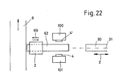
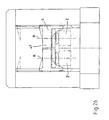
- Figures 30 to 32 are various other variants of the invention. Again, the workpiece 2 of a Workpiece carrier 5 is held, wherein the workpiece carrier 5 respectively stretched laterally from the two workpiece carriages 4, 4 'and is held. The movement of the workpiece carriage 4, 4 'along the towers 100, 101 is in sync. This variant has no rotation axis for the workpiece.
- a parallel machining process provides that along a Processing plant provided several processing stations are who make the same edits. That means, that a workpiece is not necessarily all processing stations must pass through this processing plant.
- a parallel concept is for example advantageous if long-lasting Processing steps must take place, it should be noted that the slowest processing station the overall speed determined the entire plant. Also, a redundancy of Processing stations are favorable for maintenance or failures.
- a parallel machining process has two Conveyor belts, namely a first for the blanks and a second volume for the working parts, there are alber too Concepts (for example Fig. 18), where a parallel concept with a conveyor belt can be realized, which then to Example leads through the processing station.
Description
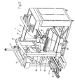
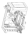
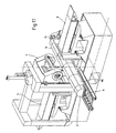
- Fig. 1, 2, 3, 5, 6, 7, 8, 9, 12, 13, 14, 17, 18
- jeweils in einer dreidimensionalen Ansicht verschiedene Varianten der Erfindung,
- Fig. 4
- in einer Ansicht, teilweise geschnitten, ein Detail der Erfindung,
- Fig. 10
- in einer Ansicht ein Detail der Erfindung,
- Fig. 11
- eine Seitenansicht nach Fig. 10
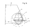
- Fig. 15
- in einer Ansicht ein weiteres Detail der Erfindung und
- Fig. 16
- eine Seitenansicht nach Fig. 15
- Fig. 19
- in einer Ansicht ein weiteres Detail der Erfindung
- Fig. 20, 21
- in einer dreidimensionalen Ansicht eine weitere Variante der erfindungsgemäßen Bearbeitungsstation;
- Fig. 22
- in einer Draufsicht eine schematische Skizze der Anordnung nach Fig. 21;
- Fig. 23 bis 27
- jeweils in Ansichten verschiedene Details der Erfindung;
- Fig. 28
- in einer schematischen Draufsicht eine weitere Variante der erfindungsgemäßen Bearbeitungsstation;
- Fig. 29
- eine detailliertere Ansicht des Konzeptes nach Fig. 28, entlang des Pfeiles XXIX und
- Fig. 30, 31, 32
- in einer Ansicht weitere verschiedene Varianten der Erfindung.
Claims (62)
- Bearbeitungsstation, wobei für das Bearbeiten von mindestens einem Werkstück (2) mindestens eine Bearbeitungseinheit (3), insbesondere eine ein Werkzeug tragende Werkzeugspindel (30) vorgesehen ist und das Werkstück (2) an eine Übergabestelle (60) herantransportierbar ist und an dieser von zumindest einem Werkstückschlitten (4) auf nehmbar ist, wobei der Werkstückschlitten (4) das Werkstück (2) für eine Bearbeitung an die Bearbeitungseinheit (3) heranfahren, kann, dadurch gekenntzeichnet, daß der werkstückschlitten (4) das Werkstück (2) während der Bearbeitung vertikal durch die Bearbeitungseinheit (3) bewegen, kann wobei das Werkstück durch den Werkstückschlitten (4) entlang nur einer vertikalen Linearachse (Y) bewegbar ist.
- Bearbeitungsstation nach Anspruch 1, dadurch gekennzeichnet, daß die Werkzeugspindel (30) relativ zum Werkstückschlitten (4) entlang zweier zur Bewegungsrichtung des werkstückschlittens (4) entlang der ersten Linearachse jeweils rechtwinklig angeordneten zweiten (X) und dritten (Z) Linearachse bewegbar ist.
- Bearbeitungsstation nach einem der vorhergehenden Ansprüche, dadurch gekennzeichnet, daß sich die Übergabestelle (60) in der Bearbeitungsstation bzw. im Arbeitsraum befindet und/oder eine Aufteilung der Achsen in werkstückschlittenachse und in Bearbeitungsachse vorgesehen ist.
- Bearbeitungsstation nach einem der vorhergehenden Ansprüche, dadurch gekennzeichnet, daß der Werkstückschlitten (4) das Werkstück (2) zumindest um eine Drehachse (A, B, C) zu drehen vermag und/oder der Werkstückschlitten (4) mehrere Werkstücke (2) trägt und/oder der werkstückschlitten (4) in einem Ständer (10) oder Turm (100) geführt ist.
- Bearbeitungsstation nach einem der vorhergehenden Ansprüche, dadurch gekennzeichnet, daß das Werkstück (2) auf einem Werkstückträger (5) aufgespannt ist und/oder das Werkstück (2) stehend, hängend, seitlich oder schräg auf dem Werkstückträger (5) aufgespannt ist.
- Bearbeitungsstation nach einem der vorhergehenden Ansprüche, dadurch gekennzeichnet, daß der Werkstückschlitten (4) das Werkstück (2) beziehungsweise den das Werkstück (2) tragenden Werkstückträger (5) von oben, schräg von der Seite und/oder von unten ergreift und hält.
- Bearbeitungsstation nach einem der vorhergehenden Ansprüche, dadurch gekennzeichnet, daß der Werkstückschlitten (4) rahmenartig oder wippenartig ausgebildet ist und/oder der Werkstückschlitten (4) tischartig ausgebildet ist und das Werkstück (2) auf dem Werkstücktisch (45) des Werkstückschlittens (4) aufliegt.
- Bearbeitungsstation nach einem der vorhergehenden Ansprüche, dadurch gekennzeichnet, daß die Drehachse rechtwinklig (A, C), parallel (B) oder winklig (CB) zur vertikalen Bewegungsrichtung (Y) des Werkstückschlittens (4) ist und/oder der Werkzeugschlitten (4) das Werkstück (2) um zwei oder drei, jeweils aufeinander rechtwinklig stehenden Achsen (A, B, C) zu drehen vermag.
- Bearbeitungssation nach einem der vorhergehenden Ansprüche, dadurch gekennzeichnet, daß an dem Werkstückschlitten (4) ein Schwenklager (42) insbesondere um die Drehachse (A) bzw. um eine horizontale Achse vorgesehen ist.
- Bearbeitungsstation nach einem der vorhergehenden Ansprüche, dadurch gekennzeichnet, daß mehrere auf dem werkstückschlitten (4) befindliche Werkstücke (2) um eine gemeinsame horizontale Drehachse (A) drehbar sind.
- Bearbeitungsstation nach einem der vorhergehenden Ansprüche, dadurch gekennzeichnet, daß an dem werkstückschlitten (4) mindestens eine, bevorzugt zwei seitliche Wangen (43) vorgesehen sind, welche drehbar einen Träger (46) tragen und der Träger (46) das Werkstück (2) oder den werkstückträger (5) hält.
- Bearbeitungsstation nach einem der vorhergehenden Ansprüche, dadurch gekennzeichnet, daß das Werkstück (2) oder der Werkstückträger (5) von einem Karussell (47) gehalten ist, welches am Träger (46) drehbar gelagert ist.
- Bearbeitungsstation nach einem der vorhergehenden Ansprüche, dadurch gekennzeichnet, daß die seitlichen Wangen (43) das Schwenklager (42) aufnehmen.
- Bearbeitungsstation nach einem der vorhergehenden Ansprüche, dadurch gekennzeichnet, daß das Karussell (47) bevorzugt um die B-Achse, insbesondere um eine vertikale Achse, verdrehbar ist.
- Bearbeitungsstation nach einem der vorhergehenden Ansprüche, dadurch gekennzeichnet, daß für jedes von dem Werkstückschlitten (4) getragenes Werkstück (2) eine eigene, insbesondere durch jeweils eigene Karusselle gebildete, bevorzugt vertikal orientierte Drehachse (B) vorgesehen ist.
- Bearbeitungsstation nach einem der vorhergehenden Ansprüche, dadurch gekennzeichnet, daß der Werkstückschlitten (4) in einem Rahmen (11) geführt ist und/oder der Werkstückschlitten (4) so geführt ist, daß eine zweiseitige Bearbeitung, insbesondere von beiden Seiten, bezüglich der Transportbahn (6) erfolgt.
- Bearbeitungsstation nach einem der vorhergehenden Ansprüche, dadurch gekennzeichnet, daß der Ständer (10) für die Führung des Werkstückschlittens (4) im Bereich der Übergabestelle (60) auf der der Bearbeitungseinheit (3) gegenüberliegenden Seite angeordnet ist.
- Bearbeitungsstation nach einem der vorhergehenden Ansprüche, dadurch gekennzeichnet, daß sich der Rahmen (11) im Bereich der Übergabestelle (60) auf beiden Seiten der Übergabestelle (60) erstreckt beziehungsweise abstützt.
- Bearbeitungsstation nach einem der vorhergehenden Ansprüche, dadurch gekennzeichnet, daß die vertikal orientierten Ständer- beziehungsweise Rahmenteile (12) Führungsschienen (15) aufweisen, auf welche sich je mindestens ein, bevorzugt zwei Führungsschuhe des Werkstückschlittens (4) bewegen.
- Bearbeitungsstation nach einem der vorhergehenden Ansprüche, dadurch gekennzeichnet, daß das Werkstück (2) entlang einer Transportbahn (6) bewegt wird und die Übergabestelle (60) Teil dieser Transportbahn (6) ist bzw. die Transportbahn (6) an der Übergabestelle (60) anschließt.
- Bearbeitungsstation nach einem der vorhergehenden Ansprüche, dadurch gekennzeichnet, daß an der Bearbeitungsstation eine erste Übergabestelle (66) für das Antransportieren und eine hiervon entfernte zweite Übergabestelle (67) für das Abtransportieren der Werkstücke (2) vorgesehen ist.
- Bearbeitungsstation nach einem der vorhergehenden Ansprüche, dadurch gekennzeichnet, daß die Bearbeitungsstation (3) Transportmittel (62) für die Bewegung des Werkstückes (2) bzw. des Werkstückträgers (5) auf der Transportbahn (6) zumindest im Bereich der Be-arbeitungsstation (1) aufweist.
- Bearbeitungsstation nach einem der vorhergehenden Ansprüche, dadurch gekennzeichnet, daß das Transportmittel (62) ein vor der Bearbeitungsstation auf der Transportbahn (6) wartendes Werkstück (2) bzw. einen Werkstückträger (5) in die Bearbeitungsstation hereintransportiert und/oder das Transportmittel (62) fertig bearbeitete Werkstücke (2) zu der in Flußrichtung hinter der Bearbeitungsstation liegenden Transportbahn transportiert.
- Bearbeitungsstation nach einem der vorhergehenden Ansprüche, dadurch gekennzeichnet, daß die Bearbeitungseinheit (3) im wesentlichen rechtwinklig zur Bewegung des Werkstückschlittens (4) bewegbar und positionierbar ist und/oder die Bearbeitungseinheit (3) eine oder mehrere Werkzeugspindeln (30) trägt und/oder die Bearbeitungsstation mehrere Bearbeitungseinheiten (3) aufweist.
- Bearbeitungsstation nach einem der vorhergehenden Ansprüche, dadurch gekennzeichnet, daß sich das Werkstück (2) während der Bearbeitung zwischen zwei Bearbeitungseinheiten (3) der Bearbeitungsstation befindet.
- Bearbeitungsstation nach einem der vorhergehenden Ansprüche, dadurch gekennzeichnet, daß die Drehachse (A) rechtwinklig zur Spindelachse (31) einerseits und rechtwinklig zur Bewegungsrichtung (Y) des Werkstückschlittens (4) andererseits ist.
- Bearbeitungsstation nach einem der vorhergehenden Ansprüche, dadurch gekennzeichnet, daß der Werkstückschlitten (4) ein Werkzeugmagazin (32) für die Bearbeitungseinheit (3) trägt und der Werkstückschlitten (4) für einen Werkzeugwechsel an der Bearbeitungseinheit (3) entsprechend positionierbar ist.
- Bearbeitungsstation nach einem der vorhergehenden Ansprüche, dadurch gekennzeichnet, daß unabhängig von der Bewegung des Werkstückschlittens auch das Werkzeugmagazin verfahrbar und positionierbar ist.
- Bearbeitungsstation nach einem der vorhergehenden Ansprüche, dadurch gekennzeichnet, daß eine Spannvorrichtung (50) vorgesehen ist, um das Werkstück (2) bzw. den das Werkstück (2) tragenden Werkstückträger (5) mit dem Werkstückschlitten (4) zu verbinden.
- Bearbeitungsstation nach einem der vorhergehenden Ansprüche, dadurch gekennzeichnet, daß die Relativbewegung (Y) des Werkstückschlittens (4) für ein Ergreifen bzw. Lösen des Werkstückes (2) bzw. des Werkstückträgers (5) von dem Werkstückschlitten (4) dient.
- Bearbeitungsstation nach einem der vorhergehenden Ansprüche, dadurch gekennzeichnet, daß eine Spannvorrichtung an dem Werkstückschlitten (4) durch einen heb- und senkbaren Greifer (500) gebildet ist und für das Heben und Senken des Greifers (500) ein Exzenterantrieb (503), welcher mit dem Werkstückschlitten (4) mitfährt, vorgesehen ist.
- Bearbeitungsstation nach einem der vorhergehenden Ansprüche, dadurch gekennzeichnet, daß an dem Schwenklager (42) ein Gewichtsausgleich (8) vorgesehen ist.
- Bearbeitungsstation nach einem der vorhergehenden Ansprüche, dadurch gekennzeichnet, daß der Gewichtsausgleich von einem Arbeitszylinder gebildet ist, der auf eine Kurbel des Trägers (46) wirkt.
- Bearbeitungsstation nach einem der vorhergehenden Ansprüche, dadurch gekennzeichnet, daß die Bearbeitungsstation (1) für die Bewegung des Werkstückes (2) zwei Türme (100, 101) aufweist, jeder Turm einen verfahrbaren Werkstückschlitten trägt und die Werkstückschlitten, gegebenenfalls gemeinsam mindestens ein Werkstück tragen.
- Bearbeitungsstation nach einem der vorhergehenden Ansprüche, dadurch gekennzeichnet, daß je ein Turm (100, 101) auf je einer Seite des Transprtweges angeordnet ist.
- Bearbeitungsstation nach einem der vorhergehenden Ansprüche, dadurch gekennzeichnet, daß die Bearbeitungsstation (1) für die Bewegung des Werkstückes (2) zwei Türme (103, 104) aufweist, die Türme (103, 104) in Transportrichtung der Werkstücke (2) hintereinander angeordnet sind und sich jeder Turm (103, 104) auf beiden Seiten des Transportweges (6) abstützt, wofür jeder Turm (103, 104) eine Öffnung (105) für den Transportweg (6) besitzt.
- Bearbeitungsstation nach einem der vorhergehenden Ansprüche, dadurch gekennzeichnet, daß sich die Übergabestelle (60) zwischen den Türmen (100, 101, 103, 104) befindet und/oder sich das Transportmittel (62) zwischen den Türmen (100, 101) befindet und/oder die Türme (100, 101) im oberen Bereich (102) verbunden sind.
- Bearbeitungsstation nach einem der vorhergehenden Ansprüche, dadurch gekennzeichnet, daß die Werkzeugspindel (30) zwischen den Türmen (103, 104) angeordnet ist.
- Bearbeitungsstation nach einem der vorhergehenden Ansprüche, dadurch gekennzeichnet, daß ein Werkstück (2) oder ein das Werkstück (2) tragender Werkstückträger (5) von zumindest einem Werkzeugschlitten (4) oder beiden Werkstückschlitten (4, 4') der beiden Türme (100, 101, 103, 104) bewegt wird.
- Bearbeitungsstation nach einem der vorhergehenden Ansprüche, dadurch gekennzeichnet, daß jeder Turm (100, 101, 103, 104) einen Antrieb für den Werkstückschlitten (4, 4') besitzt.
- Bearbeitungsstation nach einem der vorhergehenden Ansprüche, dadurch gekennzeichnet, daß die Werkstückschlittenantriebe der beiden Türme (100, 101, 103, 104) zueinander synchronisiert sind.
- Bearbeitungsstation nach einem der vorhergehenden Ansprüche, dadurch gekennzeichnet, daß die Werkstückschlitten (4, 4') beider Türme (100, 101, 103, 104) eine gemeinsame Drehachse (A) besitzen.
- Bearbeitungsstation nach einem der vorhergehenden Ansprüche, dadurch gekennzeichnet, daß die Werkstückschlitten (4, 4') je einen Drehantrieb für die gemeinsame Drehachse (A) besitzen und diese Drehantriebe zueinander synchronisierbar sind.
- Bearbeitungsstation nach einem der vorhergehenden Ansprüche, dadurch gekennzeichnet, daß der Werkstückschlitten (4, 4') für das Werkstück (2) einen Drehantrieb für eine Drehachse (B) aufweist, die parallel zur Bewegungsrichtung (Y) des Werkstückschlittens (4, 4') orientiert ist.
- Bearbeitungsstation nach einem der vorhergehenden Ansprüche, dadurch gekennzeichnet, daß die Werkstückschlitten (4, 4') beider Türme (100, 101, 103, 104) durch eine Brücke (47) verbindbar sind, wobei die Brücke (47) das mindestens eine Werkstück (2) um mindestens eine zur Bewegungsrichtung der Werkstückschlitten (4, 4') parallelen Drehachsen (B), gegebenenfalls untereinander auch unabhängig zu drehen vermag.
- Bearbeitungsstation nach einem der vorhergehenden Ansprüche, dadurch gekennzeichnet, daB das Transportmittel (62) sowohl den An- wie auch den Abtransport der unbearbeiteten beziehungsweise bearbeiteten Werkstücke (2) leistet und/oder das Transportmittel (62) ein Anförder- und ein Abfördermittel (600) aufweist, wobei auf dem Anfördermittel (601) die unbearbeiteten Werkstücke (2) angefördert und auf dem Abfördermittel (600) die bearbeiteten Werkstücke (2) abtransportiert werden.
- Bearbeitungsstation nach einem der vorhergehenden Ansprüche, dadurch gekennzeichnet, daß das Anfördermittel (601) und Abfördermittel (600) übereinander oder nebeneinander angeordnet sind.
- Bearbeitungsstation nach einem der vorhergehenden Ansprüche, dadurch gekennzeichnet, daß zwei oder mehrere Werkstücke (2) auf einem Werkstückträger (5) aufgespannt sind.
- Bearbeitungsstation nach einem der vorhergehenden Ansprüche, dadurch gekennzeichnet, daß die Werkstücke (2) auf dem Werkstückträger (5) in Längsrichtung des Transportweges oder rechtwinklig hierzu angeordnet sind.
- Bearbeitungsstation nach einem der vorhergehenden Ansprüche, dadurch gekennzeichnet, daß die Be-arbeitungsstation (1) zwei oder mehrere Werkzeugspindeln (30) aufweist und die Bearbeitungsstation (1) gleichzeitig zwei oder mehrere Werkstücke (2) bearbeitet.
- Bearbeitungsstation nach einem der vorhergehenden Ansprüche, dadurch gekennzeichnet, daß mehrere Werkstücke (2) von einem oder mehreren der Werkstückschlitten (4, 4') gleichartig oder zumindest teilweise unterschiedlich bewegt beziehungsweise gedreht werden.
- Bearbeitungsstation nach einem der vorhergehenden Ansprüche, dadurch gekennzeichnet, daß die Spindelachse (31) der Werkzeugspindel (30) parallel oder rechtwinklig zur Transportrichtung des Werkstückes (2) auf dem Transportweg orientiert sind.
- Bearbeitungsanlage, insbesondere Transferstraße, bestehend aus zumindest einem oder mehreren Bearbeitungstationen nach einer der vorhergehenden Ansprüche, wobei an allen Bearbeitungsstationen für den An- und Abtransport des Werkstückes (2) eine Transportbahn (6) vorgesehen ist.
- Bearbeitungsanlage nach dem vorhergehenden Anspruch 53,
dadurch gekennzeichnet, daß hintereinander zwei oder mehrere Bearbeitungsstationen vorgesehen sind und angeförderte Werkstücke durch eine erste Bearbeitungsstation durchgefördert werden zu einer freien Bearbeitungsstation. - Bearbeitungsanlage nach einem der vorhergehenden Ansprüche 53 und 54, dadurch gekennzeichnet, daß jedes Werkstück beziehungsweise jeder werkstückträger ein gegebenenfalls auch beschreibbares Identifikationselement trägt.
- Bearbeitungsanlage nach einem der vorhergehenden Ansprüche 53 bis 55, dadurch gekennzeichnet, daß die Bearbeitungsstationen hintereinander angeordnet sind und die Abtransportbahn der ersten Bearbeitungsstation die Antransportbahn der zweiten Bearbeitungsstation ist.
- Bearbeitungsanlage nach einem der vorhergehenden Ansprüche 53 bis 56, dadurch gekennzeichnet, daß mehrere Bearbeitungsstationen zwischen einer für die Bearbeitungsstation gemeinsamen Antransportbahn und Ab-transportbahn angeordnet sind.
- Bearbeitungsanlage nach einem der vorhergehenden Ansprüche 53 bis 57, dadurch gekennzeichnet, daß von der Abtransportbahn eine Verbindungsstation zur Antransportbahn besteht und bereits bearbeitete Werkstücke nochmals auf der Antransportbahn zur Bearbeitung herangeführt werden.
- Bearbeitungsanlage nach einem der vorhergehenden Ansprüche 53 bis 58, dadurch gekennzeichnet, daß die Bearbeitungsstationen parallel und/oder seriell zueinander angeordnet und durch eine Transportbahn verbunden sind.
- Bearbeitungsanlage nach einem der vorhergehenden Ansprüche 53 bis 59, dadurch gekennzeichnet, daß für den Transport der Werkstücke mindestens zwei im wesentlichen parallel zueinander angeordnete, nebeneinander oder übereinander verlaufende Transportbahnen vorgesehen sind.
- verfahren für das Positionieren eines Werkstückes an einer Bearbeitungseinheit, insbesondere eine ein Werkzeug trangende Werkzeugspindel, wobei das Werkstück auf einer Transportbahn an die Übergabestelle transportiert wird, dort von einem Werkstückschlitten aufgenommen, insbesondere angehoben wird und der Werkstückschlitten das Werkstück an die Bearbeitungseinheit transportiert und/oder der Werkstückschlitten das Werkstück während der Bearbeitung in vertikaler Richtung durch die Bearbeitungseinheit bewegt und das Werkstück nach Abschluß der Bearbeitung vom Werkstückschlitten an der Übergabestelle wieder abgelegt wird und das Werkstück hernach auf der Transportbahn abtransportiert wird, wobei das Werkstück entlang nur der vertikalen Linearachse durch den Werkstückschlitten bewegt wird.
- Verfahren nach dem vorgehenden Anspruch 61, dadurch gekennzeichnet, daß der Werkstückschlitten für den Ab-transport des Werkstückes angehoben wird und/oder der Werkstückschlitten erst dann an die Übergabestelle heranfährt, wenn das Werkstück eingefördert wurde.
Applications Claiming Priority (12)
| Application Number | Priority Date | Filing Date | Title |
|---|---|---|---|
| DE10231043 | 2002-07-09 | ||
| DE10231043 | 2002-07-09 | ||
| DE10232777 | 2002-07-18 | ||
| DE10232777 | 2002-07-18 | ||
| DE10238386 | 2002-08-16 | ||
| DE10238386 | 2002-08-16 | ||
| DE20217937U | 2002-11-19 | ||
| DE20217937 | 2002-11-19 | ||
| DE20218805 | 2002-12-05 | ||
| DE20218805U | 2002-12-05 | ||
| DE20304653U DE20304653U1 (de) | 2002-07-09 | 2003-03-21 | Bearbeitungsstation |
| DE20304653U | 2003-03-21 |
Publications (2)
| Publication Number | Publication Date |
|---|---|
| EP1380382A1 EP1380382A1 (de) | 2004-01-14 |
| EP1380382B1 true EP1380382B1 (de) | 2005-10-19 |
Family
ID=29741162
Family Applications (1)
| Application Number | Title | Priority Date | Filing Date |
|---|---|---|---|
| EP03015295A Expired - Lifetime EP1380382B1 (de) | 2002-07-09 | 2003-07-07 | Bearbeitungsstation mit Werkstückschlitten |
Country Status (13)
| Country | Link |
|---|---|
| US (1) | US7150706B2 (de) |
| EP (1) | EP1380382B1 (de) |
| CN (1) | CN100562398C (de) |
| AT (1) | ATE307005T1 (de) |
| AU (1) | AU2003250904A1 (de) |
| BR (1) | BR0312574A (de) |
| CA (1) | CA2491634A1 (de) |
| DE (3) | DE20304653U1 (de) |
| ES (1) | ES2252591T3 (de) |
| MX (1) | MXPA05000362A (de) |
| PL (1) | PL372828A1 (de) |
| SI (1) | SI1380382T1 (de) |
| WO (1) | WO2004004969A1 (de) |
Cited By (2)
| Publication number | Priority date | Publication date | Assignee | Title |
|---|---|---|---|---|
| DE202017101766U1 (de) | 2017-03-28 | 2018-06-29 | Starrag Gmbh | Werkzeugmaschine mit einer Schwenkbrücke |
| DE102017106569A1 (de) | 2017-03-28 | 2018-10-04 | Starrag Gmbh | Werkzeugmaschine mit einer Schwenkbrücke |
Families Citing this family (42)
| Publication number | Priority date | Publication date | Assignee | Title |
|---|---|---|---|---|
| DE10325878A1 (de) * | 2003-06-06 | 2004-12-23 | Grob-Werke Burkhart Grob E.K. | Beladesystem für eine Bearbeitungsstation |
| JP4215677B2 (ja) * | 2003-08-25 | 2009-01-28 | 日立ビアメカニクス株式会社 | レーザ加工機及びレーザ加工方法 |
| FR2861004B1 (fr) * | 2003-10-21 | 2006-12-08 | Comau Systemes France Sa | Dispositif porte-piece |
| DE10349697B4 (de) * | 2003-10-24 | 2007-03-29 | Daimlerchrysler Ag | Bearbeitungssystem zur spanenden Bearbeitung von Zylinderköpfen |
| FR2867993B1 (fr) * | 2004-03-29 | 2007-05-11 | Comau Systemes France Sa Sa | Dispositif et procede d'usinage a grande vitesse de pieces longues |
| JP4274167B2 (ja) * | 2005-10-18 | 2009-06-03 | 村田機械株式会社 | ワーク計測器付き工作機械 |
| ITTO20050765A1 (it) * | 2005-10-27 | 2007-04-28 | Biesse Spa | Centro di lavoro a controllo numerico per lastre di vetro, pietra, marmo o simili, con due o piu' teste di lavorazione |
| DE102005057658B4 (de) * | 2005-12-01 | 2008-06-26 | Manuel Burger | Vorrichtung zur Mehrfachbearbeitung |
| DE102005058347B4 (de) * | 2005-12-06 | 2014-10-23 | Schwäbische Werkzeugmaschinen GmbH | Werkzeugmaschine zur Bearbeitung von Werkstücken |
| DE102006003985A1 (de) * | 2006-01-20 | 2007-07-26 | Index-Werke Gmbh & Co. Kg Hahn & Tessky | Werkzeugmaschine |
| DE102006038499A1 (de) * | 2006-08-16 | 2008-02-21 | Grob-Werke Gmbh & Co. Kg | Bearbeitungsmaschine |
| US20100098508A1 (en) * | 2006-12-29 | 2010-04-22 | Konstantin N Kulikov | A Device for Preparation of Relief Surfaces and Method Thereof |
| WO2009035388A1 (en) | 2007-09-14 | 2009-03-19 | Flexlink Components Ab | Lifting device for a conveyor system, a conveyor system and a method |
| DE102007054267A1 (de) * | 2007-11-14 | 2009-05-20 | Alfing Kessler Sondermaschinen Gmbh | Mehrspindel-Bearbeitungsmaschine |
| DE102007054268A1 (de) * | 2007-11-14 | 2009-05-20 | Alfing Kessler Sondermaschinen Gmbh | Mehrspindel-Bearbeitungsmaschine |
| JP2009125852A (ja) * | 2007-11-22 | 2009-06-11 | Murata Mach Ltd | 工作機械、およびセンサモジュール |
| JP2009125856A (ja) * | 2007-11-22 | 2009-06-11 | Murata Mach Ltd | 工作機械、センサモジュール、および計測方法 |
| EP2316609B1 (de) * | 2009-10-27 | 2012-06-13 | Shenq Fang Yuan Technology Co., Ltd. | Mehrspindel-Arbeitsmaschine |
| WO2011118594A1 (ja) * | 2010-03-25 | 2011-09-29 | 本田技研工業株式会社 | シリンダヘッドのバルブ孔の加工方法及び加工装置、および、クランプ装置 |
| CN101972909A (zh) * | 2010-10-22 | 2011-02-16 | 襄樊东昇机械有限公司 | 焊接机器人快速段取平台 |
| JP1523249S (de) * | 2014-08-27 | 2015-05-11 | ||
| US20160074946A1 (en) * | 2014-09-12 | 2016-03-17 | Pocket NC Company | Multi-axis machining systems and related methods |
| USD788196S1 (en) | 2014-09-12 | 2017-05-30 | Pocket NC Company | Multi-axis machine |
| DE102014226333A1 (de) * | 2014-12-17 | 2016-06-23 | Homag Holzbearbeitungssysteme Gmbh | Vorrichtung und Verfahren zur Bearbeitung von Werkstücken |
| USD759736S1 (en) * | 2015-01-30 | 2016-06-21 | Jinn Fa Machine Industrial Co., Ltd. | Multi-purpose machine tool |
| USD783694S1 (en) * | 2015-04-08 | 2017-04-11 | Daishowa Seiki Kabushiki Kaisha | Measuring instruments for machine tools |
| JP5885871B1 (ja) | 2015-04-13 | 2016-03-16 | Dmg森精機株式会社 | ワーク着脱装置 |
| CN104842167B (zh) * | 2015-04-23 | 2017-05-10 | 瑞安市博宇电器有限公司 | 换向器全自动生产设备 |
| CN104827354A (zh) * | 2015-04-28 | 2015-08-12 | 佛山市普拉迪数控科技有限公司 | 一种多轴加工的数控机床 |
| DE102015121925A1 (de) | 2015-09-24 | 2017-03-30 | Alfing Kessler Sondermaschinen Gmbh | Werkzeugmaschine |
| CN105436902A (zh) * | 2015-12-09 | 2016-03-30 | 苏州金逸康自动化设备有限公司 | 一种重型球形外壳打磨机 |
| CN106112560A (zh) * | 2016-08-22 | 2016-11-16 | 江苏鼎宇机械制造股份有限公司 | 汽车前桥用高效加工装置 |
| AT519024B1 (de) * | 2016-10-17 | 2018-03-15 | Minebea Mitsumi Inc | Verfahren und Vorrichtung zur automatisierten Bearbeitung und Montage eines Werkstücks, insbesondere eines Bauteils eines Spindelmotors |
| CN107322062A (zh) * | 2017-07-31 | 2017-11-07 | 中信戴卡股份有限公司 | 一种风动铣车轮帽口毛刺装置 |
| DE202017107553U1 (de) | 2017-12-12 | 2019-03-13 | Starrag Gmbh | Werkzeugmaschine mit einer das Werkstück aufnehmenden Schwenkbrücke |
| CN108168291A (zh) * | 2018-02-11 | 2018-06-15 | 深圳市发斯特精密技术有限公司 | 双层烤炉上料装置 |
| IL257582B (en) | 2018-02-18 | 2021-08-31 | Velox Puredigital Ltd | Conveyors interfacing system and method |
| CN108672777B (zh) * | 2018-05-23 | 2020-06-05 | 赵加文 | 一种剥线刀片的自动加工设备及其切铣角度控制方法 |
| US11612927B2 (en) | 2018-07-06 | 2023-03-28 | Ats Automation Tooling Systems Inc. | System and method for flexible manufacturing |
| US20220032415A1 (en) * | 2018-12-21 | 2022-02-03 | Horkos Corp | Workpiece delivery device |
| CN110253324B (zh) * | 2019-06-28 | 2024-03-22 | 安徽嘉岳金属科技有限公司 | 一种缸筒自动化加工生产线 |
| CN113857580A (zh) * | 2021-09-08 | 2021-12-31 | 谢定 | 一种用于建筑工程的钢结构切割卸载装置 |
Family Cites Families (14)
| Publication number | Priority date | Publication date | Assignee | Title |
|---|---|---|---|---|
| US6708385B1 (en) * | 1954-07-28 | 2004-03-23 | Lemelson Medical, Education And Research Foundation, Lp | Flexible manufacturing systems and methods |
| US3854889A (en) * | 1954-07-28 | 1974-12-17 | Molins Organisation Ltd | Automatic production machinery |
| US3576540A (en) * | 1967-11-20 | 1971-04-27 | Sundstrand Corp | Plural machine tool and part handling control system |
| US3559256A (en) * | 1968-03-12 | 1971-02-02 | Jerome H Lemelson | Machine control apparatus |
| DE4307482A1 (de) * | 1993-03-10 | 1994-09-22 | Max Rhodius Gmbh | Werkzeugmaschine |
| DE4422416C1 (de) | 1994-06-29 | 1996-01-11 | Magnus Dipl Ing Gruener | Bearbeitungszentrum |
| DE4435024C2 (de) | 1994-09-26 | 1997-04-24 | Hektor Steinhilber | Bohr- und Fräsmaschine mit verfahrbarer Werkstückspannvorrichtung |
| DE4439114A1 (de) * | 1994-11-02 | 1996-05-09 | Mauser Werke Oberndorf Maschin | Verfahren und Vorrichtung zur trockenen, spanabhebenden Bearbeitung eines Werkstücks |
| DE4443467C1 (de) * | 1994-12-07 | 1996-03-28 | Strothmann Gmbh & Co Kg W | Linearantrieb |
| DE19519964A1 (de) * | 1995-05-31 | 1996-12-05 | Fibro Gmbh | Be- und Entladevorrichtung, insbesondere zum Be- und Entladen von Pressen |
| SG60075A1 (en) * | 1996-06-26 | 1999-02-22 | Starrgrasmaschinen Ag | Rigid machining centre |
| DE19753797C2 (de) | 1997-12-04 | 2001-02-22 | Buderus Schleiftechnik | Vorrichtung zum Schleifen von Werkstücken |
| AU2001275689A1 (en) * | 2000-06-29 | 2002-01-08 | Huller Hille Gmbh | System for machining work pieces comprising at least one machine tool |
| DE50102146D1 (de) * | 2000-06-29 | 2004-06-03 | Hueller Hille Gmbh | Werkzeug-maschine zur mindestens 3-achsigen bearbeitung von werkstücken |
-
2003
- 2003-03-21 DE DE20304653U patent/DE20304653U1/de not_active Expired - Lifetime
- 2003-07-07 CA CA002491634A patent/CA2491634A1/en not_active Abandoned
- 2003-07-07 ES ES03015295T patent/ES2252591T3/es not_active Expired - Lifetime
- 2003-07-07 BR BR0312574-2A patent/BR0312574A/pt not_active Application Discontinuation
- 2003-07-07 WO PCT/EP2003/007276 patent/WO2004004969A1/de not_active Application Discontinuation
- 2003-07-07 DE DE50301393T patent/DE50301393D1/de not_active Expired - Lifetime
- 2003-07-07 AU AU2003250904A patent/AU2003250904A1/en not_active Abandoned
- 2003-07-07 SI SI200330134T patent/SI1380382T1/sl unknown
- 2003-07-07 PL PL03372828A patent/PL372828A1/xx unknown
- 2003-07-07 EP EP03015295A patent/EP1380382B1/de not_active Expired - Lifetime
- 2003-07-07 AT AT03015295T patent/ATE307005T1/de active
- 2003-07-07 DE DE2003130630 patent/DE10330630A1/de not_active Withdrawn
- 2003-07-07 MX MXPA05000362A patent/MXPA05000362A/es unknown
- 2003-07-08 US US10/614,222 patent/US7150706B2/en not_active Expired - Lifetime
- 2003-07-09 CN CN03147415.2A patent/CN100562398C/zh not_active Expired - Lifetime
Cited By (3)
| Publication number | Priority date | Publication date | Assignee | Title |
|---|---|---|---|---|
| DE202017101766U1 (de) | 2017-03-28 | 2018-06-29 | Starrag Gmbh | Werkzeugmaschine mit einer Schwenkbrücke |
| DE102017106569A1 (de) | 2017-03-28 | 2018-10-04 | Starrag Gmbh | Werkzeugmaschine mit einer Schwenkbrücke |
| DE102017106569B4 (de) | 2017-03-28 | 2019-01-24 | Starrag Gmbh | Werkzeugmaschine mit einer Schwenkbrücke |
Also Published As
| Publication number | Publication date |
|---|---|
| PL372828A1 (en) | 2005-08-08 |
| US20040132595A1 (en) | 2004-07-08 |
| BR0312574A (pt) | 2005-05-10 |
| ES2252591T3 (es) | 2006-05-16 |
| SI1380382T1 (sl) | 2006-04-30 |
| DE10330630A1 (de) | 2004-01-29 |
| DE20304653U1 (de) | 2004-03-18 |
| CN100562398C (zh) | 2009-11-25 |
| CN1472039A (zh) | 2004-02-04 |
| US7150706B2 (en) | 2006-12-19 |
| ATE307005T1 (de) | 2005-11-15 |
| EP1380382A1 (de) | 2004-01-14 |
| DE50301393D1 (de) | 2005-11-24 |
| CA2491634A1 (en) | 2004-01-15 |
| AU2003250904A1 (en) | 2004-01-23 |
| WO2004004969A1 (de) | 2004-01-15 |
| MXPA05000362A (es) | 2005-08-19 |
Similar Documents
| Publication | Publication Date | Title |
|---|---|---|
| EP1380382B1 (de) | Bearbeitungsstation mit Werkstückschlitten | |
| DE3506314C2 (de) | ||
| DE102005017523B4 (de) | Verfahren zum Bearbeiten von Werkstücken mittels einer Werkzeugmaschine | |
| EP1294531B1 (de) | Anlage zur bearbeitung von werkstücken mit wenigstens einer werkzeug-maschine | |
| DE102011015741B4 (de) | Umrüstverfahren | |
| DE2756422A1 (de) | Fertigungsanlage fuer in zwei oder mehreren schritten herzustellende bauteile | |
| EP0672480A1 (de) | Transportsystem | |
| DE3440604C2 (de) | Automatische Werkzeugwechseleinrichtung für Werkzeugmaschinen, insbesondere für Universalbearbeitungszentren | |
| EP1712330A1 (de) | Fertigungs-Anlage | |
| EP1321225A2 (de) | Bearbeitungsanlage mit mindestens einer Transportbahn und mehreren Bearbeitungsstationen | |
| EP0908269A2 (de) | Werkzeugmaschinengruppe mit zwei einander gegenüberstehenden Bearbeitungseinheiten | |
| DE3722180C2 (de) | Transfermaschine | |
| WO2021089075A1 (de) | Werkstückwagen sowie werkzeugmaschine und fertigungszelle mit derartigem werkstückwagen | |
| EP1426137A2 (de) | Werkzeugmaschine | |
| EP0130309A1 (de) | Holzbearbeitungsmaschinen | |
| DE19803563C1 (de) | Werkzeugmaschine, insbesondere Drehmaschine mit wenigstens einer hängend angeordneten horizontalen Arbeitsspindel | |
| DE102020001963B4 (de) | Fertigungszelle mit Werkstückrückführung und Betriebsverfahren hierzu | |
| EP1329281A2 (de) | Werkzeugmaschine mit Stabkinematik | |
| DE102015111468A1 (de) | Bearbeitungsmaschine mit neuartiger Werkstückbeladeeinrichtung | |
| DE19756278B4 (de) | Maschinensystem zum Bearbeiten insbesondere kubischer Werkstücke | |
| EP0480191A2 (de) | Vorrichtung zum Bearbeiten von Stangen | |
| DE10058627A1 (de) | Drehmaschine | |
| DE102019007763B4 (de) | Fertigungszelle mit mindestens zwei Bearbeitungsrobotern | |
| EP3481588A1 (de) | Multifunktionales bearbeitungszentrum | |
| EP0137117A2 (de) | Werkzeugwechselvorrichtung mit einer Übergabeeinrichtung für Werkzeugträger |
Legal Events
| Date | Code | Title | Description |
|---|---|---|---|
| PUAI | Public reference made under article 153(3) epc to a published international application that has entered the european phase |
Free format text: ORIGINAL CODE: 0009012 |
|
| AK | Designated contracting states |
Kind code of ref document: A1 Designated state(s): AT BE BG CH CY CZ DE DK EE ES FI FR GB GR HU IE IT LI LU MC NL PT RO SE SI SK TR |
|
| AX | Request for extension of the european patent |
Extension state: AL LT LV MK |
|
| 17P | Request for examination filed |
Effective date: 20040417 |
|
| 17Q | First examination report despatched |
Effective date: 20040729 |
|
| AKX | Designation fees paid |
Designated state(s): AT BE BG CH CY CZ DE DK EE ES FI FR GB GR HU IE IT LI LU MC NL PT RO SE SI SK TR |
|
| GRAP | Despatch of communication of intention to grant a patent |
Free format text: ORIGINAL CODE: EPIDOSNIGR1 |
|
| GRAS | Grant fee paid |
Free format text: ORIGINAL CODE: EPIDOSNIGR3 |
|
| GRAA | (expected) grant |
Free format text: ORIGINAL CODE: 0009210 |
|
| AK | Designated contracting states |
Kind code of ref document: B1 Designated state(s): AT BE BG CH CY CZ DE DK EE ES FI FR GB GR HU IE IT LI LU MC NL PT RO SE SI SK TR |
|
| PG25 | Lapsed in a contracting state [announced via postgrant information from national office to epo] |
Ref country code: NL Free format text: LAPSE BECAUSE OF FAILURE TO SUBMIT A TRANSLATION OF THE DESCRIPTION OR TO PAY THE FEE WITHIN THE PRESCRIBED TIME-LIMIT Effective date: 20051019 Ref country code: RO Free format text: LAPSE BECAUSE OF FAILURE TO SUBMIT A TRANSLATION OF THE DESCRIPTION OR TO PAY THE FEE WITHIN THE PRESCRIBED TIME-LIMIT Effective date: 20051019 Ref country code: IE Free format text: LAPSE BECAUSE OF FAILURE TO SUBMIT A TRANSLATION OF THE DESCRIPTION OR TO PAY THE FEE WITHIN THE PRESCRIBED TIME-LIMIT Effective date: 20051019 Ref country code: FI Free format text: LAPSE BECAUSE OF FAILURE TO SUBMIT A TRANSLATION OF THE DESCRIPTION OR TO PAY THE FEE WITHIN THE PRESCRIBED TIME-LIMIT Effective date: 20051019 |
|
| REG | Reference to a national code |
Ref country code: GB Ref legal event code: FG4D Free format text: NOT ENGLISH |
|
| REG | Reference to a national code |
Ref country code: CH Ref legal event code: EP |
|
| REG | Reference to a national code |
Ref country code: IE Ref legal event code: FG4D Free format text: LANGUAGE OF EP DOCUMENT: GERMAN |
|
| REF | Corresponds to: |
Ref document number: 50301393 Country of ref document: DE Date of ref document: 20051124 Kind code of ref document: P |
|
| REG | Reference to a national code |
Ref country code: CH Ref legal event code: NV Representative=s name: PA ALDO ROEMPLER |
|
| GBT | Gb: translation of ep patent filed (gb section 77(6)(a)/1977) |
Effective date: 20051221 |
|
| PG25 | Lapsed in a contracting state [announced via postgrant information from national office to epo] |
Ref country code: BG Free format text: LAPSE BECAUSE OF FAILURE TO SUBMIT A TRANSLATION OF THE DESCRIPTION OR TO PAY THE FEE WITHIN THE PRESCRIBED TIME-LIMIT Effective date: 20060119 Ref country code: GR Free format text: LAPSE BECAUSE OF FAILURE TO SUBMIT A TRANSLATION OF THE DESCRIPTION OR TO PAY THE FEE WITHIN THE PRESCRIBED TIME-LIMIT Effective date: 20060119 Ref country code: DK Free format text: LAPSE BECAUSE OF FAILURE TO SUBMIT A TRANSLATION OF THE DESCRIPTION OR TO PAY THE FEE WITHIN THE PRESCRIBED TIME-LIMIT Effective date: 20060119 |
|
| REG | Reference to a national code |
Ref country code: SE Ref legal event code: TRGR |
|
| REG | Reference to a national code |
Ref country code: HU Ref legal event code: AG4A Ref document number: E000203 Country of ref document: HU |
|
| NLV1 | Nl: lapsed or annulled due to failure to fulfill the requirements of art. 29p and 29m of the patents act | ||
| REG | Reference to a national code |
Ref country code: ES Ref legal event code: FG2A Ref document number: 2252591 Country of ref document: ES Kind code of ref document: T3 |
|
| REG | Reference to a national code |
Ref country code: IE Ref legal event code: FD4D |
|
| ET | Fr: translation filed | ||
| PG25 | Lapsed in a contracting state [announced via postgrant information from national office to epo] |
Ref country code: SI Free format text: LAPSE BECAUSE OF NON-PAYMENT OF DUE FEES Effective date: 20060708 |
|
| PG25 | Lapsed in a contracting state [announced via postgrant information from national office to epo] |
Ref country code: BE Free format text: LAPSE BECAUSE OF NON-PAYMENT OF DUE FEES Effective date: 20060731 Ref country code: MC Free format text: LAPSE BECAUSE OF NON-PAYMENT OF DUE FEES Effective date: 20060731 |
|
| PLBE | No opposition filed within time limit |
Free format text: ORIGINAL CODE: 0009261 |
|
| STAA | Information on the status of an ep patent application or granted ep patent |
Free format text: STATUS: NO OPPOSITION FILED WITHIN TIME LIMIT |
|
| 26N | No opposition filed |
Effective date: 20060720 |
|
| PG25 | Lapsed in a contracting state [announced via postgrant information from national office to epo] |
Ref country code: PT Free format text: LAPSE BECAUSE OF NON-PAYMENT OF DUE FEES Effective date: 20070409 |
|
| REG | Reference to a national code |
Ref country code: PT Ref legal event code: MM4A Free format text: LAPSE DUE TO NON-PAYMENT OF FEES Effective date: 20070409 |
|
| REG | Reference to a national code |
Ref country code: SI Ref legal event code: KO00 Effective date: 20070327 |
|
| BERE | Be: lapsed |
Owner name: *GROB-WERKE BURKHART GROB E.K. Effective date: 20060731 |
|
| REG | Reference to a national code |
Ref country code: CH Ref legal event code: PUE Owner name: GROB-WERKE GMBH & CO. KG Free format text: GROB-WERKE BURKHART GROB E.K.#INDUSTRIESTRASSE 4#87719 MINDELHEIM (DE) -TRANSFER TO- GROB-WERKE GMBH & CO. KG#INDUSTRIESTRASSE 4#87719 MINDELHEIM (DE) |
|
| REG | Reference to a national code |
Ref country code: HU Ref legal event code: FH1C Representative=s name: DR. JAKAB JUDIT, S.B.G. AND K. Effective date: 20071211 Ref country code: HU Ref legal event code: GB9C Owner name: GROB-WERKE GMBH UND CO. KG, DE Free format text: FORMER OWNER: GROB-WERKE BURKHART GROB E.K., DE Effective date: 20071211 Ref country code: HU Ref legal event code: GB9C Owner name: GROB-WERKE GMBH & CO. KG, DE Free format text: FORMER OWNER(S): GROB-WERKE BURKHART GROB E.K., DE Ref country code: HU Ref legal event code: FH1C Free format text: FORMER REPRESENTATIVE(S): DR. JAKAB JUDIT, S.B.G. & K. SZABADALMI UEGYVIVOEI IRODA, HU Representative=s name: DR. JAKAB JUDIT, S.B.G. & K. SZABADALMI UEGYVI, HU |
|
| REG | Reference to a national code |
Ref country code: GB Ref legal event code: 732E |
|
| REG | Reference to a national code |
Ref country code: ES Ref legal event code: PC2A |
|
| REG | Reference to a national code |
Ref country code: FR Ref legal event code: TP |
|
| PG25 | Lapsed in a contracting state [announced via postgrant information from national office to epo] |
Ref country code: EE Free format text: LAPSE BECAUSE OF FAILURE TO SUBMIT A TRANSLATION OF THE DESCRIPTION OR TO PAY THE FEE WITHIN THE PRESCRIBED TIME-LIMIT Effective date: 20051019 |
|
| PG25 | Lapsed in a contracting state [announced via postgrant information from national office to epo] |
Ref country code: TR Free format text: LAPSE BECAUSE OF FAILURE TO SUBMIT A TRANSLATION OF THE DESCRIPTION OR TO PAY THE FEE WITHIN THE PRESCRIBED TIME-LIMIT Effective date: 20051019 Ref country code: LU Free format text: LAPSE BECAUSE OF NON-PAYMENT OF DUE FEES Effective date: 20060707 |
|
| REG | Reference to a national code |
Ref country code: CH Ref legal event code: PCAR Free format text: ALDO ROEMPLER PATENTANWALT;BRENDENWEG 11 POSTFACH 154;9424 RHEINECK (CH) |
|
| PG25 | Lapsed in a contracting state [announced via postgrant information from national office to epo] |
Ref country code: CY Free format text: LAPSE BECAUSE OF FAILURE TO SUBMIT A TRANSLATION OF THE DESCRIPTION OR TO PAY THE FEE WITHIN THE PRESCRIBED TIME-LIMIT Effective date: 20051019 |
|
| REG | Reference to a national code |
Ref country code: FR Ref legal event code: PLFP Year of fee payment: 14 |
|
| PGFP | Annual fee paid to national office [announced via postgrant information from national office to epo] |
Ref country code: SK Payment date: 20160706 Year of fee payment: 14 Ref country code: SE Payment date: 20160721 Year of fee payment: 14 Ref country code: HU Payment date: 20160704 Year of fee payment: 14 Ref country code: CZ Payment date: 20160707 Year of fee payment: 14 |
|
| REG | Reference to a national code |
Ref country code: FR Ref legal event code: PLFP Year of fee payment: 15 |
|
| PG25 | Lapsed in a contracting state [announced via postgrant information from national office to epo] |
Ref country code: CZ Free format text: LAPSE BECAUSE OF NON-PAYMENT OF DUE FEES Effective date: 20170707 |
|
| REG | Reference to a national code |
Ref country code: SE Ref legal event code: EUG |
|
| REG | Reference to a national code |
Ref country code: SK Ref legal event code: MM4A Ref document number: E 400 Country of ref document: SK Effective date: 20170707 |
|
| PG25 | Lapsed in a contracting state [announced via postgrant information from national office to epo] |
Ref country code: SE Free format text: LAPSE BECAUSE OF NON-PAYMENT OF DUE FEES Effective date: 20170708 Ref country code: HU Free format text: LAPSE BECAUSE OF NON-PAYMENT OF DUE FEES Effective date: 20170708 |
|
| PG25 | Lapsed in a contracting state [announced via postgrant information from national office to epo] |
Ref country code: SK Free format text: LAPSE BECAUSE OF NON-PAYMENT OF DUE FEES Effective date: 20170707 |
|
| REG | Reference to a national code |
Ref country code: FR Ref legal event code: PLFP Year of fee payment: 16 |
|
| PGFP | Annual fee paid to national office [announced via postgrant information from national office to epo] |
Ref country code: AT Payment date: 20190719 Year of fee payment: 17 |
|
| PGFP | Annual fee paid to national office [announced via postgrant information from national office to epo] |
Ref country code: CH Payment date: 20190725 Year of fee payment: 17 |
|
| REG | Reference to a national code |
Ref country code: CH Ref legal event code: PL |
|
| REG | Reference to a national code |
Ref country code: AT Ref legal event code: MM01 Ref document number: 307005 Country of ref document: AT Kind code of ref document: T Effective date: 20200707 |
|
| PG25 | Lapsed in a contracting state [announced via postgrant information from national office to epo] |
Ref country code: LI Free format text: LAPSE BECAUSE OF NON-PAYMENT OF DUE FEES Effective date: 20200731 Ref country code: CH Free format text: LAPSE BECAUSE OF NON-PAYMENT OF DUE FEES Effective date: 20200731 |
|
| PG25 | Lapsed in a contracting state [announced via postgrant information from national office to epo] |
Ref country code: AT Free format text: LAPSE BECAUSE OF NON-PAYMENT OF DUE FEES Effective date: 20200707 |
|
| PGFP | Annual fee paid to national office [announced via postgrant information from national office to epo] |
Ref country code: FR Payment date: 20210722 Year of fee payment: 19 Ref country code: IT Payment date: 20210730 Year of fee payment: 19 |
|
| PGFP | Annual fee paid to national office [announced via postgrant information from national office to epo] |
Ref country code: ES Payment date: 20210819 Year of fee payment: 19 Ref country code: GB Payment date: 20210722 Year of fee payment: 19 |
|
| PGFP | Annual fee paid to national office [announced via postgrant information from national office to epo] |
Ref country code: DE Payment date: 20220621 Year of fee payment: 20 |
|
| GBPC | Gb: european patent ceased through non-payment of renewal fee |
Effective date: 20220707 |
|
| PG25 | Lapsed in a contracting state [announced via postgrant information from national office to epo] |
Ref country code: FR Free format text: LAPSE BECAUSE OF NON-PAYMENT OF DUE FEES Effective date: 20220731 |
|
| PG25 | Lapsed in a contracting state [announced via postgrant information from national office to epo] |
Ref country code: GB Free format text: LAPSE BECAUSE OF NON-PAYMENT OF DUE FEES Effective date: 20220707 |
|
| REG | Reference to a national code |
Ref country code: DE Ref legal event code: R071 Ref document number: 50301393 Country of ref document: DE |
|
| PG25 | Lapsed in a contracting state [announced via postgrant information from national office to epo] |
Ref country code: IT Free format text: LAPSE BECAUSE OF NON-PAYMENT OF DUE FEES Effective date: 20220707 |
|
| REG | Reference to a national code |
Ref country code: ES Ref legal event code: FD2A Effective date: 20230825 |
|
| PG25 | Lapsed in a contracting state [announced via postgrant information from national office to epo] |
Ref country code: ES Free format text: LAPSE BECAUSE OF NON-PAYMENT OF DUE FEES Effective date: 20220708 |