EP1380371A1 - Unité d'alésage, en particulier pour poignée de porte, avec mécanisme différentiel pour l'ajustage radial des outils - Google Patents
Unité d'alésage, en particulier pour poignée de porte, avec mécanisme différentiel pour l'ajustage radial des outils Download PDFInfo
- Publication number
- EP1380371A1 EP1380371A1 EP03015340A EP03015340A EP1380371A1 EP 1380371 A1 EP1380371 A1 EP 1380371A1 EP 03015340 A EP03015340 A EP 03015340A EP 03015340 A EP03015340 A EP 03015340A EP 1380371 A1 EP1380371 A1 EP 1380371A1
- Authority
- EP
- European Patent Office
- Prior art keywords
- tools
- pin
- tool
- holder
- grip
- Prior art date
- Legal status (The legal status is an assumption and is not a legal conclusion. Google has not performed a legal analysis and makes no representation as to the accuracy of the status listed.)
- Granted
Links
Images


Classifications
-
- B—PERFORMING OPERATIONS; TRANSPORTING
- B23—MACHINE TOOLS; METAL-WORKING NOT OTHERWISE PROVIDED FOR
- B23Q—DETAILS, COMPONENTS, OR ACCESSORIES FOR MACHINE TOOLS, e.g. ARRANGEMENTS FOR COPYING OR CONTROLLING; MACHINE TOOLS IN GENERAL CHARACTERISED BY THE CONSTRUCTION OF PARTICULAR DETAILS OR COMPONENTS; COMBINATIONS OR ASSOCIATIONS OF METAL-WORKING MACHINES, NOT DIRECTED TO A PARTICULAR RESULT
- B23Q1/00—Members which are comprised in the general build-up of a form of machine, particularly relatively large fixed members
- B23Q1/72—Auxiliary arrangements; Interconnections between auxiliary tables and movable machine elements
- B23Q1/76—Steadies; Rests
-
- B—PERFORMING OPERATIONS; TRANSPORTING
- B23—MACHINE TOOLS; METAL-WORKING NOT OTHERWISE PROVIDED FOR
- B23B—TURNING; BORING
- B23B29/00—Holders for non-rotary cutting tools; Boring bars or boring heads; Accessories for tool holders
- B23B29/24—Tool holders for a plurality of cutting tools, e.g. turrets
- B23B29/248—Tool holders for a plurality of cutting tools, e.g. turrets with individually adjustable toolholders
-
- B—PERFORMING OPERATIONS; TRANSPORTING
- B23—MACHINE TOOLS; METAL-WORKING NOT OTHERWISE PROVIDED FOR
- B23B—TURNING; BORING
- B23B3/00—General-purpose turning-machines or devices, e.g. centre lathes with feed rod and lead screw; Sets of turning-machines
- B23B3/22—Turning-machines or devices with rotary tool heads
- B23B3/26—Turning-machines or devices with rotary tool heads the tools of which perform a radial movement; Rotary tool heads thereof
-
- B—PERFORMING OPERATIONS; TRANSPORTING
- B23—MACHINE TOOLS; METAL-WORKING NOT OTHERWISE PROVIDED FOR
- B23B—TURNING; BORING
- B23B31/00—Chucks; Expansion mandrels; Adaptations thereof for remote control
- B23B31/40—Expansion mandrels
- B23B31/4006—Gripping the work or tool by a split sleeve
-
- Y—GENERAL TAGGING OF NEW TECHNOLOGICAL DEVELOPMENTS; GENERAL TAGGING OF CROSS-SECTIONAL TECHNOLOGIES SPANNING OVER SEVERAL SECTIONS OF THE IPC; TECHNICAL SUBJECTS COVERED BY FORMER USPC CROSS-REFERENCE ART COLLECTIONS [XRACs] AND DIGESTS
- Y10—TECHNICAL SUBJECTS COVERED BY FORMER USPC
- Y10T—TECHNICAL SUBJECTS COVERED BY FORMER US CLASSIFICATION
- Y10T82/00—Turning
- Y10T82/16—Severing or cut-off
- Y10T82/16426—Infeed means
- Y10T82/16442—Infeed means with means to circumrotate tool[s] about work
-
- Y—GENERAL TAGGING OF NEW TECHNOLOGICAL DEVELOPMENTS; GENERAL TAGGING OF CROSS-SECTIONAL TECHNOLOGIES SPANNING OVER SEVERAL SECTIONS OF THE IPC; TECHNICAL SUBJECTS COVERED BY FORMER USPC CROSS-REFERENCE ART COLLECTIONS [XRACs] AND DIGESTS
- Y10—TECHNICAL SUBJECTS COVERED BY FORMER USPC
- Y10T—TECHNICAL SUBJECTS COVERED BY FORMER US CLASSIFICATION
- Y10T82/00—Turning
- Y10T82/25—Lathe
- Y10T82/2512—Lathe having facing tool fed transverse to work
-
- Y—GENERAL TAGGING OF NEW TECHNOLOGICAL DEVELOPMENTS; GENERAL TAGGING OF CROSS-SECTIONAL TECHNOLOGIES SPANNING OVER SEVERAL SECTIONS OF THE IPC; TECHNICAL SUBJECTS COVERED BY FORMER USPC CROSS-REFERENCE ART COLLECTIONS [XRACs] AND DIGESTS
- Y10—TECHNICAL SUBJECTS COVERED BY FORMER USPC
- Y10T—TECHNICAL SUBJECTS COVERED BY FORMER US CLASSIFICATION
- Y10T82/00—Turning
- Y10T82/25—Lathe
- Y10T82/2527—Lathe having hollow cutter head
-
- Y—GENERAL TAGGING OF NEW TECHNOLOGICAL DEVELOPMENTS; GENERAL TAGGING OF CROSS-SECTIONAL TECHNOLOGIES SPANNING OVER SEVERAL SECTIONS OF THE IPC; TECHNICAL SUBJECTS COVERED BY FORMER USPC CROSS-REFERENCE ART COLLECTIONS [XRACs] AND DIGESTS
- Y10—TECHNICAL SUBJECTS COVERED BY FORMER USPC
- Y10T—TECHNICAL SUBJECTS COVERED BY FORMER US CLASSIFICATION
- Y10T82/00—Turning
- Y10T82/25—Lathe
- Y10T82/2531—Carriage feed
- Y10T82/2541—Slide rest
- Y10T82/2543—Multiple tool support
Definitions
- the invention concerns boring machines for complex parts, and in particular it concerns a new boring unit for complex parts, particularly door handles, provided with a differential control system for the rotary tools.
- the boring machines currently used comprise a piece-holding spindle, a tailstock, one or more tools.
- the piece to be worked is positioned on the piece-holding spindle and locked onto it.
- the piece-holding spindle is set rotating and the tool is guided on the surface of the piece to be worked, in such a way as to shape it.
- the main aim of the new boring unit is to allow the working of one end of eccentric or asymmetrical parts.
- Another aim of the new boring unit is to allow the boring of the connection end of handles.
- a further aim of the new boring unit is to ensure the rapid and correct positioning of each piece to be bored.
- a further aim of the new boring unit is to ensure the boring of any piece, symmetrical or asymmetrical, with no need to rotate it.
- Another aim of the new boring unit is to allow the tools to be rotated on the object to be bored.
- differential control system comprising a square pin for fixing the piece, two concentric rotary cylinders that are also concentric with the square pin, a tool-holder applied to the outer cylinder, a bevel gear pair between the inner cylinder and the tool radial translation mechanisms.
- the fixing pin is preferably a square traction pin that receives and locks the piece by holding it through its central square hole.
- the two coaxial cyinders are set rotating by two separate electric motors.
- the outer cylinder rotates the tool-holder and the tools around the end of the handle to be bored.
- the rotation speed of the inner cylinder is differentiated, increased or decreased, compared to the rotation speed of the outer cylinder, so that the bevel gear pair, due to the difference in the rotation speed, operates the radial translation mechanisms of the tools.
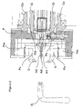
- Figures 1 and 2 respectively show a general cross section and a detailed cross section of the new boring unit for complex pieces, in particular for door handles, with differential control system, comprising a square traction pin (A), two rotary cylinders (Ci, Ce) concentric with each other and with the square pin (A), a tool holder (P) applied to the outer cylinder (Ce) and equipped with radial translation mechanisms (Pm) of the tools (U), a bevel gear pair (Pe, Cie) between the inner cylinder (Ci) and the radial translation mechanisms (Pm) of the tools (U), two motors (Mi, Me) for the rotation of the two concentric cylinders (Ci, Ce).
- differential control system comprising a square traction pin (A), two rotary cylinders (Ci, Ce) concentric with each other and with the square pin (A), a tool holder (P) applied to the outer cylinder (Ce) and equipped with radial translation mechanisms (Pm) of the tools (U), a
- the square traction pin (A) is a pin with square cross section, similar to and slightly smaller than a classic square pin used to connect the two handles on the two sides of a door, whose end (Ae) may be expanded.
- Said square traction pin (A) isn't set rotating by any motor and its axial rotation is preferably locked. Consequently the piece, that is, the handle (O), held by the end of said square pin (A) doesn't turn.
- the two rotary cylinders (Ci, Ce) are coaxially positioned around the square traction pin (A).
- Each one of the two cylinders (Ci, Ce) is connected with an electric motor (Mi, Me) on the side of the axial translation mechanism (At) of the square pin (A).
- Said electric motors make said two cylinders (Ci, Ce) rotate in the same direction and they may have the same or different rotation speed.
- the inner cylinder (Ci) is provided with a conical toothing (Cie) at its end opposite the motor.
- the outer cylinder (Ce) supports, at its end opposite the motor (Me), the tool-holder (P). Said tool-holder (P) is integrally connected with the cylinder (Ce), so that the rotation of the cylinder (Ce) itself sets rotating also the tool-holder (P) and the tools (U) themselves.
- the tool-holder (P) comprises suitable couplings (Pu) for the tools (U), suitable radial translation mechanisms (Pm) of said couplings (Pu) and a bevel gear wheel (Pe).
- the couplings (Pu) of the tools (U) are preferably two and are arranged radially opposite each other, in such a way as to direct the tools (U) towards the rotation centre.
- Both the couplings (Pu) of the tools (U) and the tools (U) themselves are preferably L or Z-shaped, so as to allow the boring process to be carried out, that is, to ensure the action of the tools (U) in a concentric area outside the tool-holder (P) on the side opposite the outer cylinder (Ce).
- the bevel gear wheel (Pe) meshes with the conical toothing (Cie) of the inner cylinder (Ci) and is connected with the radial translation mechanisms (Pm) of the couplings (Pu) of the tools (U).
- the arrangement of the square traction pin (A) and of the coaxial cylinders (Ci, Ce) is such that the expansion end (Ae) is positioned between the tools (U) supported by the tool-holder (P) of the outer cylinder (Ce).
- Said electronic circuit (X) reads the instantaneous positions and the speeds of both motors (Mi, Me) of the rotary cylinders (Ci, Ce), calculates the relative position of the tool-holder (P) according to the relative positions of the two motors (Mi, Me) and controls them so that, though rotating, they remain synchronized, thus ensuring also the controlled shifting according to a precise movement diagram that corresponds to the working path.
- the motors (Mi, Me) and the axial translation mechanism (Am) of the square pin (A) are operated.
- the combination of the rotation speeds of the two motors (Mi, Me), that is, of the two cylinders (Ci, Ce) and of the advance speed of the square pin (A) makes it possible to carry out the desired, controlled or programmed boring operation.
- the new boring unit for complex parts in particular for door handles, with differential control system, offers several advantages:
Landscapes
- Engineering & Computer Science (AREA)
- Mechanical Engineering (AREA)
- Retarders (AREA)
- Lock And Its Accessories (AREA)
- Drilling And Boring (AREA)
- Auxiliary Devices For Machine Tools (AREA)
- Securing Of Glass Panes Or The Like (AREA)
- Special Wing (AREA)
Applications Claiming Priority (2)
| Application Number | Priority Date | Filing Date | Title |
|---|---|---|---|
| IT2002PD000193A ITPD20020193A1 (it) | 2002-07-12 | 2002-07-12 | Unita' di alesatura per pezzi complessi, particolarmente per manigliedi porte, con sistema differenziale |
| ITPD20020193 | 2002-07-12 |
Publications (2)
| Publication Number | Publication Date |
|---|---|
| EP1380371A1 true EP1380371A1 (fr) | 2004-01-14 |
| EP1380371B1 EP1380371B1 (fr) | 2011-02-23 |
Family
ID=29727289
Family Applications (1)
| Application Number | Title | Priority Date | Filing Date |
|---|---|---|---|
| EP03015340A Expired - Lifetime EP1380371B1 (fr) | 2002-07-12 | 2003-07-08 | Unité d'alésage, en particulier pour poignée de porte, avec mécanisme différentiel pour l'ajustage radial des outils |
Country Status (7)
| Country | Link |
|---|---|
| US (1) | US6862967B2 (fr) |
| EP (1) | EP1380371B1 (fr) |
| AT (1) | ATE499166T1 (fr) |
| DE (1) | DE60336100D1 (fr) |
| ES (1) | ES2360487T3 (fr) |
| IT (1) | ITPD20020193A1 (fr) |
| PT (1) | PT1380371E (fr) |
Cited By (4)
| Publication number | Priority date | Publication date | Assignee | Title |
|---|---|---|---|---|
| CN100455388C (zh) * | 2005-12-21 | 2009-01-28 | 石础辉 | 一种全自动车削设备 |
| WO2009033929A2 (fr) * | 2007-09-11 | 2009-03-19 | Index-Werke Gmbh & Co. Kg Hahn & Tessky | Tour |
| CN104596404A (zh) * | 2015-01-26 | 2015-05-06 | 哈尔滨飞机工业集团有限责任公司 | 一种接头孔同轴误差检测工具及检测方法 |
| CN105478820A (zh) * | 2015-10-14 | 2016-04-13 | 常州市鹰皇冠进出口有限公司 | 一种柴油机加工用一体式夹头 |
Families Citing this family (3)
| Publication number | Priority date | Publication date | Assignee | Title |
|---|---|---|---|---|
| US7918155B2 (en) * | 2007-12-12 | 2011-04-05 | Mahle International Gmbh | Piston with a cooling gallery |
| DE202010001331U1 (de) * | 2009-09-03 | 2010-04-15 | Kennametal Inc. | Innenfräser |
| DE102012112189A1 (de) * | 2012-12-12 | 2014-06-12 | Sandvik Materials Technology Deutschland Gmbh | Vorrichtung und Verfahren zum Abstechen eines Rohrs |
Citations (3)
| Publication number | Priority date | Publication date | Assignee | Title |
|---|---|---|---|---|
| US4411178A (en) * | 1981-06-04 | 1983-10-25 | Power Cutting Incorporated | Pipe end preparation machine |
| DE19921919A1 (de) * | 1999-05-12 | 2000-11-30 | Schuebel Engineering Gmbh | Multifunktionale Vorrichtungen zur Bearbeitung des Endbereichs von Werkstücken durch Drehen mit mindestens einem umlaufenden Werkzeug und stehendem Werkstück |
| US20010017069A1 (en) | 1998-07-10 | 2001-08-30 | Mats Heijkenskjold | Lathe and method for turning a work piece on a lathe |
Family Cites Families (3)
| Publication number | Priority date | Publication date | Assignee | Title |
|---|---|---|---|---|
| US4430913A (en) * | 1982-03-23 | 1984-02-14 | Kaiser Steel Corporation | Cut-off and face machine |
| ATE58855T1 (de) * | 1986-03-07 | 1990-12-15 | Chuang Kuo Huey | Getriebe eines revolverkopfes bestehend aus einer zwillingsscheibe fuer cnc-maschinen. |
| DE10143387B4 (de) * | 2001-09-04 | 2010-07-29 | Komet Group Gmbh | Werkzeugkopf für den Einsatz in Werkzeugmaschinen |
-
2002
- 2002-07-12 IT IT2002PD000193A patent/ITPD20020193A1/it unknown
-
2003
- 2003-07-08 DE DE60336100T patent/DE60336100D1/de not_active Expired - Lifetime
- 2003-07-08 EP EP03015340A patent/EP1380371B1/fr not_active Expired - Lifetime
- 2003-07-08 ES ES03015340T patent/ES2360487T3/es not_active Expired - Lifetime
- 2003-07-08 PT PT03015340T patent/PT1380371E/pt unknown
- 2003-07-08 AT AT03015340T patent/ATE499166T1/de not_active IP Right Cessation
- 2003-07-10 US US10/616,789 patent/US6862967B2/en not_active Expired - Lifetime
Patent Citations (3)
| Publication number | Priority date | Publication date | Assignee | Title |
|---|---|---|---|---|
| US4411178A (en) * | 1981-06-04 | 1983-10-25 | Power Cutting Incorporated | Pipe end preparation machine |
| US20010017069A1 (en) | 1998-07-10 | 2001-08-30 | Mats Heijkenskjold | Lathe and method for turning a work piece on a lathe |
| DE19921919A1 (de) * | 1999-05-12 | 2000-11-30 | Schuebel Engineering Gmbh | Multifunktionale Vorrichtungen zur Bearbeitung des Endbereichs von Werkstücken durch Drehen mit mindestens einem umlaufenden Werkzeug und stehendem Werkstück |
Cited By (6)
| Publication number | Priority date | Publication date | Assignee | Title |
|---|---|---|---|---|
| CN100455388C (zh) * | 2005-12-21 | 2009-01-28 | 石础辉 | 一种全自动车削设备 |
| WO2009033929A2 (fr) * | 2007-09-11 | 2009-03-19 | Index-Werke Gmbh & Co. Kg Hahn & Tessky | Tour |
| WO2009033929A3 (fr) * | 2007-09-11 | 2009-05-22 | Index Werke Kg Hahn & Tessky | Tour |
| US8087332B2 (en) | 2007-09-11 | 2012-01-03 | Index-Werke Gmbh & Co. Kg Hahn & Tessky | Lathe |
| CN104596404A (zh) * | 2015-01-26 | 2015-05-06 | 哈尔滨飞机工业集团有限责任公司 | 一种接头孔同轴误差检测工具及检测方法 |
| CN105478820A (zh) * | 2015-10-14 | 2016-04-13 | 常州市鹰皇冠进出口有限公司 | 一种柴油机加工用一体式夹头 |
Also Published As
| Publication number | Publication date |
|---|---|
| ITPD20020193A1 (it) | 2004-01-12 |
| US6862967B2 (en) | 2005-03-08 |
| DE60336100D1 (de) | 2011-04-07 |
| PT1380371E (pt) | 2011-04-18 |
| ATE499166T1 (de) | 2011-03-15 |
| EP1380371B1 (fr) | 2011-02-23 |
| ES2360487T3 (es) | 2011-06-06 |
| US20040011166A1 (en) | 2004-01-22 |
Similar Documents
| Publication | Publication Date | Title |
|---|---|---|
| CA2616628C (fr) | Machine universelle pour usinage avant traitement de pignons coniques et procede correspondant | |
| US11858054B2 (en) | Gearing method with tooth finishing and combination tool therefor | |
| JP2008529810A (ja) | 傘歯車の硬化前機械加工を行うための装置及び方法 | |
| US4742738A (en) | Machine adjustable boring bar assembly and method | |
| US6862967B2 (en) | Boring unit for complex parts, particularly for door handles, with differential control systems | |
| KR20170021291A (ko) | 치형 휠들의 치형부들의 치형부 플랭크들 내에 언더커팅들을 포함하기 위한 방법 | |
| JP2020075348A (ja) | 歯車製造装置および歯付きワークピースの製造方法 | |
| JP6968068B2 (ja) | ギアを作製または加工するための方法、およびそのために設計された歯切り機械 | |
| EP1635975B1 (fr) | Appareil d'usinage orbital a element d'entrainement equipe de tiges d'entrainement | |
| JP7440216B2 (ja) | 歯車の仕上げ研削加工の方法 | |
| JP3917844B2 (ja) | 両面歯切りされたフェースギアの歯切り加工 | |
| US20080232916A1 (en) | Process and Device for Producing Threads, Especially for Boring Rods or the Like | |
| US3494388A (en) | Turning and boring head | |
| JP2000141120A (ja) | トロコイド工具およびトロコイド工具による加工法 | |
| JP2020527107A (ja) | 工具交換装置、このような工具交換装置を備えた工作機械、および関連する方法 | |
| KR20080047363A (ko) | 베벨기어의 소프트 기계가공을 위한 만능 기계 및 그 대응방법 | |
| SU1509235A1 (ru) | Хонинговально-доводочный станок | |
| JPH0825211A (ja) | 砥石切込み装置およびホーニング盤 | |
| KR0129785Y1 (ko) | 절단 보조 장치 | |
| KR20070008659A (ko) | 작업 헤드 | |
| JP2012030360A (ja) | 傘歯車のソフト機械加工用万能機械と対応する方法 | |
| MXPA98010772A (es) | Procedimiento y dispositivo para la fabricacion de contornos externos e internos diferentes de laforma circular | |
| JPH05301101A (ja) | U軸ホルダー | |
| JPH091416A (ja) | 工作機械 | |
| JP2001157919A (ja) | 歯車シェービング加工方法、及びシェービングツール |
Legal Events
| Date | Code | Title | Description |
|---|---|---|---|
| PUAI | Public reference made under article 153(3) epc to a published international application that has entered the european phase |
Free format text: ORIGINAL CODE: 0009012 |
|
| AK | Designated contracting states |
Kind code of ref document: A1 Designated state(s): AT BE BG CH CY CZ DE DK EE ES FI FR GB GR HU IE IT LI LU MC NL PT RO SE SI SK TR |
|
| AX | Request for extension of the european patent |
Extension state: AL LT LV MK |
|
| 17P | Request for examination filed |
Effective date: 20040713 |
|
| AKX | Designation fees paid |
Designated state(s): AT BE BG CH CY CZ DE DK EE ES FI FR GB GR HU IE IT LI LU MC NL PT RO SE SI SK TR |
|
| 17Q | First examination report despatched |
Effective date: 20090428 |
|
| GRAP | Despatch of communication of intention to grant a patent |
Free format text: ORIGINAL CODE: EPIDOSNIGR1 |
|
| GRAS | Grant fee paid |
Free format text: ORIGINAL CODE: EPIDOSNIGR3 |
|
| GRAA | (expected) grant |
Free format text: ORIGINAL CODE: 0009210 |
|
| AK | Designated contracting states |
Kind code of ref document: B1 Designated state(s): AT BE BG CH CY CZ DE DK EE ES FI FR GB GR HU IE IT LI LU MC NL PT RO SE SI SK TR |
|
| REG | Reference to a national code |
Ref country code: GB Ref legal event code: FG4D |
|
| REG | Reference to a national code |
Ref country code: CH Ref legal event code: EP |
|
| REG | Reference to a national code |
Ref country code: IE Ref legal event code: FG4D |
|
| REF | Corresponds to: |
Ref document number: 60336100 Country of ref document: DE Date of ref document: 20110407 Kind code of ref document: P |
|
| REG | Reference to a national code |
Ref country code: DE Ref legal event code: R096 Ref document number: 60336100 Country of ref document: DE Effective date: 20110407 |
|
| REG | Reference to a national code |
Ref country code: PT Ref legal event code: SC4A Free format text: AVAILABILITY OF NATIONAL TRANSLATION Effective date: 20110411 |
|
| RAP2 | Party data changed (patent owner data changed or rights of a patent transferred) |
Owner name: MEI S.R.L. |
|
| REG | Reference to a national code |
Ref country code: ES Ref legal event code: FG2A Ref document number: 2360487 Country of ref document: ES Kind code of ref document: T3 Effective date: 20110606 |
|
| REG | Reference to a national code |
Ref country code: NL Ref legal event code: VDEP Effective date: 20110223 |
|
| PG25 | Lapsed in a contracting state [announced via postgrant information from national office to epo] |
Ref country code: GR Free format text: LAPSE BECAUSE OF FAILURE TO SUBMIT A TRANSLATION OF THE DESCRIPTION OR TO PAY THE FEE WITHIN THE PRESCRIBED TIME-LIMIT Effective date: 20110524 Ref country code: SE Free format text: LAPSE BECAUSE OF FAILURE TO SUBMIT A TRANSLATION OF THE DESCRIPTION OR TO PAY THE FEE WITHIN THE PRESCRIBED TIME-LIMIT Effective date: 20110223 |
|
| PG25 | Lapsed in a contracting state [announced via postgrant information from national office to epo] |
Ref country code: BG Free format text: LAPSE BECAUSE OF FAILURE TO SUBMIT A TRANSLATION OF THE DESCRIPTION OR TO PAY THE FEE WITHIN THE PRESCRIBED TIME-LIMIT Effective date: 20110523 Ref country code: NL Free format text: LAPSE BECAUSE OF FAILURE TO SUBMIT A TRANSLATION OF THE DESCRIPTION OR TO PAY THE FEE WITHIN THE PRESCRIBED TIME-LIMIT Effective date: 20110223 Ref country code: SI Free format text: LAPSE BECAUSE OF FAILURE TO SUBMIT A TRANSLATION OF THE DESCRIPTION OR TO PAY THE FEE WITHIN THE PRESCRIBED TIME-LIMIT Effective date: 20110223 Ref country code: BE Free format text: LAPSE BECAUSE OF FAILURE TO SUBMIT A TRANSLATION OF THE DESCRIPTION OR TO PAY THE FEE WITHIN THE PRESCRIBED TIME-LIMIT Effective date: 20110223 Ref country code: CY Free format text: LAPSE BECAUSE OF FAILURE TO SUBMIT A TRANSLATION OF THE DESCRIPTION OR TO PAY THE FEE WITHIN THE PRESCRIBED TIME-LIMIT Effective date: 20110223 Ref country code: FI Free format text: LAPSE BECAUSE OF FAILURE TO SUBMIT A TRANSLATION OF THE DESCRIPTION OR TO PAY THE FEE WITHIN THE PRESCRIBED TIME-LIMIT Effective date: 20110223 Ref country code: AT Free format text: LAPSE BECAUSE OF FAILURE TO SUBMIT A TRANSLATION OF THE DESCRIPTION OR TO PAY THE FEE WITHIN THE PRESCRIBED TIME-LIMIT Effective date: 20110223 |
|
| PG25 | Lapsed in a contracting state [announced via postgrant information from national office to epo] |
Ref country code: EE Free format text: LAPSE BECAUSE OF FAILURE TO SUBMIT A TRANSLATION OF THE DESCRIPTION OR TO PAY THE FEE WITHIN THE PRESCRIBED TIME-LIMIT Effective date: 20110223 Ref country code: DK Free format text: LAPSE BECAUSE OF FAILURE TO SUBMIT A TRANSLATION OF THE DESCRIPTION OR TO PAY THE FEE WITHIN THE PRESCRIBED TIME-LIMIT Effective date: 20110223 |
|
| PG25 | Lapsed in a contracting state [announced via postgrant information from national office to epo] |
Ref country code: RO Free format text: LAPSE BECAUSE OF FAILURE TO SUBMIT A TRANSLATION OF THE DESCRIPTION OR TO PAY THE FEE WITHIN THE PRESCRIBED TIME-LIMIT Effective date: 20110223 Ref country code: SK Free format text: LAPSE BECAUSE OF FAILURE TO SUBMIT A TRANSLATION OF THE DESCRIPTION OR TO PAY THE FEE WITHIN THE PRESCRIBED TIME-LIMIT Effective date: 20110223 |
|
| PLBE | No opposition filed within time limit |
Free format text: ORIGINAL CODE: 0009261 |
|
| STAA | Information on the status of an ep patent application or granted ep patent |
Free format text: STATUS: NO OPPOSITION FILED WITHIN TIME LIMIT |
|
| 26N | No opposition filed |
Effective date: 20111124 |
|
| PG25 | Lapsed in a contracting state [announced via postgrant information from national office to epo] |
Ref country code: MC Free format text: LAPSE BECAUSE OF NON-PAYMENT OF DUE FEES Effective date: 20110731 |
|
| REG | Reference to a national code |
Ref country code: CH Ref legal event code: PL |
|
| REG | Reference to a national code |
Ref country code: DE Ref legal event code: R097 Ref document number: 60336100 Country of ref document: DE Effective date: 20111124 |
|
| GBPC | Gb: european patent ceased through non-payment of renewal fee |
Effective date: 20110708 |
|
| REG | Reference to a national code |
Ref country code: FR Ref legal event code: ST Effective date: 20120330 |
|
| REG | Reference to a national code |
Ref country code: IE Ref legal event code: MM4A |
|
| PG25 | Lapsed in a contracting state [announced via postgrant information from national office to epo] |
Ref country code: LI Free format text: LAPSE BECAUSE OF NON-PAYMENT OF DUE FEES Effective date: 20110731 Ref country code: CH Free format text: LAPSE BECAUSE OF NON-PAYMENT OF DUE FEES Effective date: 20110731 Ref country code: FR Free format text: LAPSE BECAUSE OF NON-PAYMENT OF DUE FEES Effective date: 20110801 |
|
| PG25 | Lapsed in a contracting state [announced via postgrant information from national office to epo] |
Ref country code: GB Free format text: LAPSE BECAUSE OF NON-PAYMENT OF DUE FEES Effective date: 20110708 |
|
| PG25 | Lapsed in a contracting state [announced via postgrant information from national office to epo] |
Ref country code: IE Free format text: LAPSE BECAUSE OF NON-PAYMENT OF DUE FEES Effective date: 20110708 |
|
| PG25 | Lapsed in a contracting state [announced via postgrant information from national office to epo] |
Ref country code: LU Free format text: LAPSE BECAUSE OF NON-PAYMENT OF DUE FEES Effective date: 20110708 |
|
| PG25 | Lapsed in a contracting state [announced via postgrant information from national office to epo] |
Ref country code: TR Free format text: LAPSE BECAUSE OF FAILURE TO SUBMIT A TRANSLATION OF THE DESCRIPTION OR TO PAY THE FEE WITHIN THE PRESCRIBED TIME-LIMIT Effective date: 20110223 |
|
| PG25 | Lapsed in a contracting state [announced via postgrant information from national office to epo] |
Ref country code: HU Free format text: LAPSE BECAUSE OF FAILURE TO SUBMIT A TRANSLATION OF THE DESCRIPTION OR TO PAY THE FEE WITHIN THE PRESCRIBED TIME-LIMIT Effective date: 20110223 |
|
| PGFP | Annual fee paid to national office [announced via postgrant information from national office to epo] |
Ref country code: IT Payment date: 20180629 Year of fee payment: 16 Ref country code: DE Payment date: 20180727 Year of fee payment: 16 Ref country code: ES Payment date: 20180801 Year of fee payment: 16 |
|
| PGFP | Annual fee paid to national office [announced via postgrant information from national office to epo] |
Ref country code: CZ Payment date: 20180703 Year of fee payment: 16 |
|
| PGFP | Annual fee paid to national office [announced via postgrant information from national office to epo] |
Ref country code: PT Payment date: 20180706 Year of fee payment: 16 |
|
| PG25 | Lapsed in a contracting state [announced via postgrant information from national office to epo] |
Ref country code: CZ Free format text: LAPSE BECAUSE OF NON-PAYMENT OF DUE FEES Effective date: 20190708 |
|
| REG | Reference to a national code |
Ref country code: DE Ref legal event code: R119 Ref document number: 60336100 Country of ref document: DE |
|
| PG25 | Lapsed in a contracting state [announced via postgrant information from national office to epo] |
Ref country code: DE Free format text: LAPSE BECAUSE OF NON-PAYMENT OF DUE FEES Effective date: 20200201 Ref country code: PT Free format text: LAPSE BECAUSE OF NON-PAYMENT OF DUE FEES Effective date: 20200108 |
|
| PG25 | Lapsed in a contracting state [announced via postgrant information from national office to epo] |
Ref country code: IT Free format text: LAPSE BECAUSE OF NON-PAYMENT OF DUE FEES Effective date: 20190708 |
|
| REG | Reference to a national code |
Ref country code: ES Ref legal event code: FD2A Effective date: 20201126 |
|
| PG25 | Lapsed in a contracting state [announced via postgrant information from national office to epo] |
Ref country code: ES Free format text: LAPSE BECAUSE OF NON-PAYMENT OF DUE FEES Effective date: 20190709 |