EP1380366B1 - Vorschubvorrichtung zum intermittierenden Zuführen eines bandförmigen Rohlings zu einer Presse und Verfahren zum Betrieb derselben - Google Patents
Vorschubvorrichtung zum intermittierenden Zuführen eines bandförmigen Rohlings zu einer Presse und Verfahren zum Betrieb derselben Download PDFInfo
- Publication number
- EP1380366B1 EP1380366B1 EP02015172A EP02015172A EP1380366B1 EP 1380366 B1 EP1380366 B1 EP 1380366B1 EP 02015172 A EP02015172 A EP 02015172A EP 02015172 A EP02015172 A EP 02015172A EP 1380366 B1 EP1380366 B1 EP 1380366B1
- Authority
- EP
- European Patent Office
- Prior art keywords
- dead center
- rod
- center position
- threaded spindle
- arm
- Prior art date
- Legal status (The legal status is an assumption and is not a legal conclusion. Google has not performed a legal analysis and makes no representation as to the accuracy of the status listed.)
- Expired - Lifetime
Links
- 238000000034 method Methods 0.000 title claims abstract description 15
- 230000008878 coupling Effects 0.000 claims description 4
- 238000010168 coupling process Methods 0.000 claims description 4
- 238000005859 coupling reaction Methods 0.000 claims description 4
- 238000007789 sealing Methods 0.000 claims 1
- 230000006835 compression Effects 0.000 description 8
- 238000007906 compression Methods 0.000 description 8
- 238000012545 processing Methods 0.000 description 8
- 239000002184 metal Substances 0.000 description 7
- 238000005096 rolling process Methods 0.000 description 7
- 239000000314 lubricant Substances 0.000 description 6
- 230000002093 peripheral effect Effects 0.000 description 6
- 238000004080 punching Methods 0.000 description 6
- 238000009423 ventilation Methods 0.000 description 6
- 230000007704 transition Effects 0.000 description 4
- 241000237942 Conidae Species 0.000 description 2
- 230000001133 acceleration Effects 0.000 description 2
- 238000003754 machining Methods 0.000 description 2
- 230000000284 resting effect Effects 0.000 description 2
- 230000009471 action Effects 0.000 description 1
- 238000005452 bending Methods 0.000 description 1
- 230000015572 biosynthetic process Effects 0.000 description 1
- 210000000078 claw Anatomy 0.000 description 1
- 238000004891 communication Methods 0.000 description 1
- 230000001934 delay Effects 0.000 description 1
- 230000001419 dependent effect Effects 0.000 description 1
- 238000013461 design Methods 0.000 description 1
- 238000004049 embossing Methods 0.000 description 1
- 230000003116 impacting effect Effects 0.000 description 1
- 230000003993 interaction Effects 0.000 description 1
- 239000010687 lubricating oil Substances 0.000 description 1
- 238000012423 maintenance Methods 0.000 description 1
- 230000000149 penetrating effect Effects 0.000 description 1
- 230000008569 process Effects 0.000 description 1
- 238000012549 training Methods 0.000 description 1
Images


Classifications
-
- B—PERFORMING OPERATIONS; TRANSPORTING
- B21—MECHANICAL METAL-WORKING WITHOUT ESSENTIALLY REMOVING MATERIAL; PUNCHING METAL
- B21D—WORKING OR PROCESSING OF SHEET METAL OR METAL TUBES, RODS OR PROFILES WITHOUT ESSENTIALLY REMOVING MATERIAL; PUNCHING METAL
- B21D43/00—Feeding, positioning or storing devices combined with, or arranged in, or specially adapted for use in connection with, apparatus for working or processing sheet metal, metal tubes or metal profiles; Associations therewith of cutting devices
- B21D43/02—Advancing work in relation to the stroke of the die or tool
- B21D43/04—Advancing work in relation to the stroke of the die or tool by means in mechanical engagement with the work
- B21D43/08—Advancing work in relation to the stroke of the die or tool by means in mechanical engagement with the work by rollers
- B21D43/09—Advancing work in relation to the stroke of the die or tool by means in mechanical engagement with the work by rollers by one or more pairs of rollers for feeding sheet or strip material
-
- Y—GENERAL TAGGING OF NEW TECHNOLOGICAL DEVELOPMENTS; GENERAL TAGGING OF CROSS-SECTIONAL TECHNOLOGIES SPANNING OVER SEVERAL SECTIONS OF THE IPC; TECHNICAL SUBJECTS COVERED BY FORMER USPC CROSS-REFERENCE ART COLLECTIONS [XRACs] AND DIGESTS
- Y10—TECHNICAL SUBJECTS COVERED BY FORMER USPC
- Y10T—TECHNICAL SUBJECTS COVERED BY FORMER US CLASSIFICATION
- Y10T152/00—Resilient tires and wheels
- Y10T152/10—Tires, resilient
- Y10T152/10036—Cushion and pneumatic combined
Definitions
- the present invention relates to a feed device for intermittently supplying a band-shaped blank to one with tools for intermittent Editing the band-shaped blank equipped Press, which feed device a housing and a threaded spindle housing arranged on the housing, a arranged on a harmonic upper feed roller and a lower shaft disposed on a lower shaft Feed roller having which feed rollers intended are, the supplied blank by a two-sided To seize terminals and through an intermittent To advance rotational movement intermittently, by which waves at least one with an intermittent working electric servomotor is drivingly connected and the harmonic in one over a swinging shaft at the Housing hinged rocker is mounted by means of which they move against the lower shaft and away from it is.
- the invention further relates to a method for operation of the aforementioned feed device, which feed device has a control device and interact with a press that is a moving one Upper tool and has a fixed lower tool, which upper tool with one between an upper Dead center position and a bottom dead center position movable plunger is connected, and the one press control having, with the control device of Feed device is connected, and in which the slot of between a top dead center position and a bottom dead center position movable connecting rod has upper and a lower end, the first arm of the second double-armed lever device via a slot passing bolts in engagement with the connecting rod stands, wherein for introducing a new band-shaped blank between the upper feed roller and the lower feed roller Feed roller, the upper feed roller in a high-lift position is driven to give a pre-eminent position in this position Distance between the upper feed roller and the set lower feed roller.
- the invention relates to a method for operating the feed device of the aforementioned Type in which the feed device is a control device and cooperates with a press, a moving upper tool and a fixed lower tool has, which upper tool with an intermediate a top dead center position and a bottom dead center Tot Vietnamese movable plunger is connected, and having a press control device, with the Control device of the feed device in connection stands, and in which the slot of between a top dead center position and a bottom dead center position movable connecting rod an upper and a lower end comprising the first arm of a first double-armed lever device via a bolt penetrating the slot is engaged.
- the invention also relates to a method for Operation of the feed device of the aforementioned Type in which the feed device is a control device and cooperates with a press, the a moving upper tool and a fixed lower tool has, which upper tool with an intermediate a top dead center position and a bottom dead center Tot Vietnamese movable plunger is connected, and having a press control associated with the control device the feed device is in communication, and in which the slot of the between an upper Dead center position and a bottom dead center position movable Pleuels has an upper and a lower end, the first arm has a first double-armed lever device via a bolt passing through the slot in Engage with the connecting rod, which ram of one driven by rotating drive and the eccentric disc of the connecting rod is driven by a drive motor, which Upper tool Cutter pins for precise positioning the band-shaped blank in the press during the machining process the same, which pegs in pre-punched positioning holes in the band-shaped blank are moved into which pins a conical Head section, wherein the upper feed roller then away from the
- the presses mentioned here are in particular high-speed presses with stroke rates up to 2000 Strokes / minute. These presses are equipped with tools for machining one (or more) supplied band-shaped Blank, with punching, embossing, Bending, riveting, threading, etc. are performed.
- a processing step e.g. a punching
- no Forward movement of the band-shaped blank Often he will precisely positioned by means of gripping pins arranged in the tools So arrested.
- the band-shaped blank After completion of the processing step, after, for example, a punching tool been moved out of the punched hole is, the band-shaped blank by a predetermined Route advanced and stopped again, so that the next processing step to be performed can.
- Feed movement of the band-shaped Blanks are made by one (or more, at Inlet and outlet of the press). or feed unit (or feed units) to the ribbon-shaped blank intermittently from a supply roll deduct and deliver to the press.
- These feeders usually have Feed links on to advance the ribbon-shaped blank. This is clamped by the feed members and moved forward. When the feed links again return to their original position, the clamping is canceled. The clamping is additionally during the period temporarily suspended during which the tools on the band-shaped blank a processing step perform, especially in the case of pegs.
- feeders with electric Servo motors become known.
- a first servomotor the feed operation of the clamping members and another, second servomotor the intermittent lifting associated with a clamping member or band-shaped blank.
- Such servomotors are manufactured by several companies and sold. The operation of these servomotors is electronically controlled. Show these new feeders as feed members completely cylindrical, on Shafts arranged feed rollers, which intermittently always rotate in the same direction. From these feed rollers is one in one with the other servomotor Driven connected component stored due to its operation this feed roller against the band-shaped blank for clamping it and moved away from it for release becomes.
- Another goal is a device too create, in which the frame is a threaded spindle housing in which the threaded spindle is arranged is which threaded spindle rigid with a sleeve part is connected, the play on roller bearings in the threaded spindle housing is stored, so that the threaded spindle is stored in the threaded spindle housing without play.
- Yet another object of the invention is a Device to show in which the with the threaded spindle rigidly connected sleeve part of a multipart Clamping sleeve is, in which the drive shaft of the other Servomotor protrudes so that the drive shaft the other servo motor frictionally with the threaded spindle is connected, which when mounting the other Servomotor by connecting its drive shaft with the threaded spindle on the clamping sleeve the final position of the servo motor by the threaded spindle housing precisely mounted threaded spindle is determined.
- a still further object of the invention is a Method for operating the feed device mentioned above to create, in which the connecting rod in his lower Dead center position is moved, the adjusting nut moved downward by a rotation of the threaded spindle until the upper feed roller due to the.
- the Compression springs on the swingarm exerted pressure on the band-shaped blank rests, and then the adjusting nut is moved downwards until the bolt of both ends of the slot has a distance, so that lifting movements of the connecting rod with a fixed bolt are possible.
- a still further object of the invention is a Method for operating the feed device of the beginning to create type mentioned, in which the attitude the intermediate release position of the plunger by his rotating drive in an angular position in front of its lower Dead center position is brought, in which angular position the conical head sections of the fishing pins only partially protrude into the positioning holes, and the Eccentric disc of the connecting rod in an angular position the top dead center position is brought, the angular distance the plunger between said angular position and the bottom dead center position equal to the angular distance the eccentric disc between her Angular position and the top dead center is, then the nut is moved down until the strip-shaped blank due to the lifting of the upper feed roller is loose, and that the position of the adjusting nut for said angular position of the eccentric disc and the corresponding angular position of the plunger in the corresponding control devices are stored.
- the clamping sleeve Due to the design of the clamping sleeve, the is an integral part of the threaded spindle, there is the Freedom to select different servomotors and to assemble, and in particular standardized standard motors, because no specially made drive shafts such Servo motors are necessary.
- the formation of the feed device must basically fulfill 3 main functions, namely the High ventilation (insert belt), the belt thickness adjustment (the upper roller lies on the tape, play in the slot of the connecting rod) and intermediate ventilation (ventilation before each Punching process).
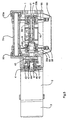
- the device has a housing 1.
- One first servomotor 2, which simplifies the electronic Control 3 is indicated, is at its flange 4 flanged by bolts 5 on the housing 1.
- This first servomotor 2 is known per se Way controlled so that it intermittently intermittent Rotary movements executes. The duration and the Extent of each step of the rotary motion depending on the in the downstream press controlled to be performed processing.
- This servomotor 2 has a drive shaft 6.
- the harmonic 8, 9 with the upper feed roller 10 and the lower shaft 20, 21 with the lower feed roller 22 is arranged, which supplied to the band-shaped blank 7 usually a metal band, intermittently advance.
- the harmonic is in an axial servomotor side first shaft section 8 and one in one axial distance from this first shaft portion 8 arranged Servomotorfernen, second shaft section 9 divided. Between these shaft sections 8, 9 is a upper feed roller 10 kept clamped.
- the servomotor remote, second shaft section 9 is from a clamping screw 11 supported on it axially interspersed, with the servomotor side, first Shaft section 8 is in screw engagement.
- This upper feed roller 10 which consists of several Parts exists and is very lightly constructed, rejects the Shape of a hollow circular cylinder with an axial interior 12 with an inner peripheral wall 13 and two end surface portions 14 and 15 on. See Figure 3.
- the transition region 16 between the end surface portion 14 and the inner peripheral wall 13 of the inner space 12 has the shape of a truncated cone shell.
- the transition region 17 between the End surface portion 15 and the inner peripheral wall 13 of the Interior 12 the shape of a Kegelstumpfmahtels.
- the mutually facing ends of the shaft sections 8, 9 also have a truncated cone-shaped Sections 18 and 19, respectively.
- the lower shaft 20, 21 is also in one axial servo motor side, first shaft portion 20 and one at an axial distance from this first shaft portion 20 arranged remote servomotor, second shaft portion 21 split. Between these shaft sections 20, 21, the lower feed roller 22 is clamped held.
- the servomotor remote, second shaft section 21 is of a clamping screw supported on it 23 axially interspersed, with the servomotor side, first Shaft section 20 is in screw engagement.
- This lower feed roller 22 which consists of several Parts exists and is very lightly constructed, rejects the Shape of a hollow circular cylinder with an axial interior 24 with an inner peripheral wall 25 and two end surface portions 26 and 27 on.
- transition region 28 between the end surface portion 26 and the inner peripheral wall 25 of the inner space 24 has the shape of a truncated cone shell.
- transition region 29 between the End surface portion 27 and the inner peripheral wall 25 of the Interior 24 the shape of a truncated cone mantle.
- the mutually facing ends of the shaft sections 20, 21 also have a truncated cone-shaped Section 30 or 31.
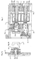
- the servo motor side, first section 8 of Harmonic and the servo motor side first section 20 the lower shaft remain in place, such as in of Figure 2 is shown. So they will not be moved.
- the servo motor remote, second section 9 of the harmonic and the servo motor remote second portion 21 of the lower shaft are in dissolved clamping screws 11, 23 in the direction the arrow C has been moved axially. This is the lie Feed rollers 10, 22 free and can be removed from the waves become. It should be noted that in the figure 3 the axial distances of the components exaggerated drawn large are. The free space between the respective sections, that is their distance must be so large be that the rollers for removal in the radial direction can be moved freely.
- the servo motor side, first section 8 of the harmonic is about a roller bearing 32 in a later to be described Rocker 33, i. the swing section 33a stored.
- the lubricant space of the rolling bearing 32 is by means of Seals 34a, 34b sealed.
- the servomotor remote, second section 9 of Harmonic is about rolling bearings 35 in the swing section 33b stored.
- the lubricant space of the rolling bearing 35 is by means of Seals 36a, 36b sealed.
- the servo motor side, first section 20 of the Lower shaft is mounted on a rolling bearing 36 in the housing 1.
- the lubricant space of the rolling bearing 36 is by means of a seal 37 sealed.
- the servomotor remote, second section 21 of Lower shaft is mounted on roller bearings 38 and 92 in the housing 1.
- the lubricant space of the rolling bearing 38 is by means of Seals 39a, 39b sealed.
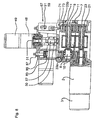
- a first preferred embodiment is the stored in the rocker 33 harmonic, the means exactly that stored in the swing section 33a Servomotor side, first shaft section 8 of the harmonic in drive connection with the first servomotor 1.
- the first shaft section 8 is provided with a Oldham coupling 40 is connected, of which in Fig. 7b the cross-plate 41 is shown separately.
- This Oldham clutch 40 is necessary because the first shaft section 8 (and obviously all associated with him Parts of the device) transverse movements relative to the stationary Drive shaft 6 of the servomotor 2 performs.
- This Oldham clutch 40 is of an upper Spur gear 42 followed, with a lower spur gear 43 meshes, which with the servomotor side, first Shaft portion 20 of the lower shaft is connected.
- connection of the upper spur gear 42 with the drive shaft 6 of the servomotor 2 is performed by a multi-part clamping sleeve with a first clamping sleeve part 44 and a second clamping sleeve part 45.
- clamping sleeve parts 44, 45 take place by means of ring clamping elements 46th
- the clamping screws are indicated by the reference numeral 47.
- the upper spur gear 42 is integral with formed the second clamping sleeve part 45, whereby a considerable savings in moving masses is achieved.
- the servomotor is close Part of the Oldham clutch also in one piece with formed the second clamping sleeve part 45.
- a still further preferred embodiment is in Figures 8, 9, 9a shown.
- the top roller 10 is frictionally engaged with the metal band rotates.
- the servo motor side second shaft portion 20 of the lower shaft from the servomotor 2 driven.
- this shaft section 20 formed integrally with the second clamping sleeve part 45, so again there is a minimum rotating mass.
- a further servomotor 48 On a threaded spindle housing 67 is a further servomotor 48 arranged. His electronic Control, i. whose housing is indicated at 49.
- This servomotor 48 serves to drive a Threaded spindle 50.
- the servomotor 48 is merely an example to consider the drive of the threaded spindle 50. It can also 48 different drives from the servo motor to be available.
- the drive shaft of the servomotor 48 is indicated by the reference numeral 51.
- the connection between the drive shaft 51 of the servo motor 48 and the threaded spindle 50 takes place by means of a multipart clamping sleeve, a first clamping sleeve part 52, a second Clamping sleeve part 53 and ring clamping elements 54 has.
- the Clamping sleeve parts 52, 53 are by means of clamping screws 55 curious against each other.
- the second clamping sleeve part 53 is over a Claw clutch 113 connected to the threaded spindle 50.
- the threaded spindle 50 is in turn via rolling bearings 56 and 112 mounted in the threaded spindle housing 67 or housing 1.
- the threaded spindle 50 is independent stored free of play by the servo motor 48.
- ring clamping elements for connection Serve with the smooth motor shaft, can be a standard Servomotor, so no custom made used become.
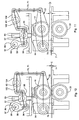
- This adjusting nut 57 On this adjusting nut 57 is a double-armed Lever 93 with a first arm 94 and a second Arm 95 stored.
- This lever 93 is in the present Description text referred to as the second double-armed lever 93.
- Adjusting nut 57 has a square cross-sectional shape and in a likewise a square cross-sectional shape having interior of the first double-armed Lever 93 is inserted. This is the adjusting nut 57 secured against twisting.
- This connecting rod 96 is seated on an eccentric disc 97, which via a shaft 98 with a third drive motor 99, for example, a servo motor, drivingly connected is.
- the control of the drive motor is indicated by the reference numeral 100.
- the second arm 95 of the first double-armed Lever 93 is a tab 101 on the first arm 102 of a hinged second double-armed lever 103.
- the second double-armed lever 103 is mounted on a shaft 60.
- the second arm 104 of the second double-armed lever 103 is fork-shaped, as in FIGS. 4 with the fork levers designating reference numerals 65, 66th is shown.
- the shaft 60 is in the threaded spindle housing 67th sealed by means of seals 61, 62 oil-tight, so that a closed threaded spindle housing 67 as a closed Lube space is present in which the threaded spindle 50 and the components described maintenance are arranged in a closed space.
- fork levers 65 and 66 are about a Ball-head connection to an upper shaft portion 68 or 69 one generally designated 70, and 71, respectively Control rod articulated, with lower shank sections 72 and 73 are screwed.
- the described shaft sections are by means of lock nuts 74 and 75 against a Twisting secured.
- the control rods are at their lower end hinged to the rocker 33.
- the rocker 33 in which the upper feed roller 10 is stored at its other end connected to a shaft 79.
- This shaft 79 is in the housing 1 stored.
- the bearings 80, 80a are in FIG. 5 located.
- the rocker 33 is by compression springs 83, 84th clamped against the lower feed roller 22.
- the contact pressure of the compression springs 83, 84 is by means of threaded spindles 85, 86 and lock nuts 87, 88, which are supported on the threaded spindle housing 67, set.
- the feed device described is to determines a ribbon-shaped blank 7, e.g. a metal band 7, one with tools for intermittent editing fed to the belt-shaped blank equipped press.
- the punch press 76 has a drive 77 on.
- This drive 77 can, as the expert in general is known to comprise an electric motor having a Crankshaft or a shaft with eccentric discs has.
- This crankshaft or eccentric disc is in Drive connection with a connecting rod 78.
- a ram 105 is articulated.
- the ram 105 carries an upper tool 106, thus in the operation of the punch press 76 is moved up and down.
- the upper tool 106 is compatible with processing tools, e.g. Stamp 107 equipped.
- control devices 49, 110 of the feed device and the punch press 76 communicate with each other, since the operation of the feed device matched to the operation of the punch press 76 have to be.
- the positions of the schematic parts of the feed device shown shown in continuous operation Rotate in continuous operation the upper feed roller 10 and the lower feed roller 22, which are driven by the servo motor 2 ago intermittently, so that the band-shaped blank 7 as general is known to be progressively advanced.
- the Punching press 76 has a moving upper tool 106 and a fixed lower tool 110.
- the upper tool 106 is connected to a plunger 105.
- the pestle 105 is driven by a rotary drive 77, e.g. electric motors and crankshaft or eccentric shaft, via a connecting rod 78 driven, the connecting rod 78 purely schematically the Drive connection between the drive 77 and the plunger 105 represents.
- the plunger is between an upper Tot Vietnamese ein and a bottom dead center position.bewegbar.
- the thickness of the strip-shaped blank 7 and according to the distance between the upper feed roller 10 and the lower feed roller 22 is in the Figure 10 with the letter E shown.
- the upper feed roller 10 To be able to, the upper feed roller 10 must be raised be so that they have a given distance D from the lower feed roller 22 which is larger than the Distance E is. This distance D and the lifted Position of the upper feed roller 10 are in the figure 11th shown.
- This position of the feed roller 10 is in the professional world referred to as Hochlcombposition.
- the bolt 58 is due to the of the Compression springs 82, 84 via the rocker 33 and the lever devices 93 and 103 at the lower end of the slot 59 at.
- Adjusting nut 57 By the downward movement of the Adjusting nut 57 is the first arm 94 of the first double-armed Lever 93 pivoted up and her second arm 95 pivoted down. This second arm 95 pulls the first arm 102 of the second double-armed lever device 103 also down. Thus, the second arm 104 of the second double-armed lever device 103 pivoted upwards. Consequently, the control rod assembly 68-75 lifted and thus the rocker 33 with the upper feed roller 10 mounted therein Hochlrangeposition the upper feed roller 10 pivoted in which they the said distance D from the lower Feed roller 22, so that a new band-shaped Blank 7 can be inserted.
- the upper feed roller must 10 rest on the band-shaped blank 7, wherein through the upper feed roller 10 and the lower feed roller 22 a clamping force for a frictional engagement on the strip-shaped blank 7 must be exercised.
- This clamping force is due to the compression springs 83, 84 generated. So the bolt 58 is not allowed to open anymore the lower end of the slot 59 rest. This will be the adjusting nut 57 by rotating the threaded spindle 50 lowered from the high ventilation position until the upper Feed roller 10 rests on the band-shaped blank 7. By a continued lowering movement of the adjusting nut 57, the first double-armed lever 93 is forced one To perform pivoting movement, since the rocker is not moves more because the upper feed roller 10 through the Compression springs 83, 84 resting on the band-shaped blank 7 is held.
- the said pivoting movement causes that the first arm 94 with the bolt 58 upwards pivots, so that the bolt 58 in the running hole 59 between whose ends are located. That means that the connecting rod 96 can perform strokes, without that an action on the bolt 58 takes place.
- This Eisenlstructure ein is by the Connecting rod 96 causes.
- the punch press 76 is in the stroke position driven, in which the intermediate ventilation takes place should and in which position the conical head sections 109 of the catching pins 108 partially in the positioning holes retracted. This position can be seen in FIG.
- the connecting rod 96 of the feeding device is now at the same time by the actuation of its drive motor 99 in a position before its top dead center position moved up.
- This angular position and the top dead center also an angular distance available.
- the one mentioned in connection with the punch press Angular distance is equal to that of the feed device existing angular distance.
- the adjusting nut 57 by rotating the threaded spindle 50 moves downward. This comes the bolt 58 to rest against the lower end of the slot 59. The adjusting nut 57 is then further down moves, so that due to the now occurring pivoting movements the lever devices and the rocker 33 the upper feed roller 10 releases the band-shaped blank. In this released state of the band-shaped blank manually detectable loose. This position of the adjusting nut 57 becomes along with the respective angular positions stored in the control devices 49 and 111.
Landscapes
- Engineering & Computer Science (AREA)
- Mechanical Engineering (AREA)
- Press Drives And Press Lines (AREA)
- Advancing Webs (AREA)
Description
Claims (11)
- Vorschubvorrichtung zum intermittierenden Zuführen eines bandförmigen Rohlings (7) zu einer mit Werkzeugen zum intermittierenden Bearbeiten des bandförmigen Rohlings (7) ausgerüsteten Presse, welche Vorschubvorrichtung ein Gehäuse (1) und ein auf dem Gehäuse (1) angeordnetes Gewindespindelgehäuse (64), eine auf einer Oberwelle (8, 9) angeordnete obere Vorschubwalze (10) und eine auf einer Unterwelle (20, 21) angeordnete untere Vorschubwalze (22) aufweist, welche Vorschubwalzen (10, 22) dazu bestimmt sind, den zuzuführenden Rohling (7) durch ein beidseitiges Klemmen zu ergreifen und durch eine intermittierende Rotationsbewegung intermittierend vorzuschieben, von welchen Wellen (8, 9; 20, 21) mindestens eine mit einem intermittierend arbeitenden elektrischen Servomotor (2) antriebsverbunden ist und die Oberwelle (8, 9) in einer über eine Schwingenwelle (79) am Gehäuse angelenkten Schwinge gelagert ist, mittels welcher sie gegen die Unterwelle (20, 21) und von derselben weg bewegbar ist, gekennzeichnet durch einen Motor (48) mit einer Gewindespindel (50) und eine Steuervorrichtung (49), auf welcher Gewindespindel (50) eine Verstellmutter (57) angeordnet und durch ein Rotieren der Gewindespindel (50) entlang derselben bewegbar ist, durch eine von einem Antriebsmotor (99) getriebene Exzenterscheibe (97), auf welcher ein Pleuel (96) gelagert ist, der beim von der Exzenterscheibe (97) entfernten Ende ein mindestens annähernd parallel zur Gewindespindel (50) verlaufenden Langloch (59) aufweist, durch eine erste, auf der Verstellmutter (57) gelagerte doppelarmige Hebelvorrichtung (93, 94, 95) und eine zweite, auf einer im Gewindespindelgehäuse (64) getragenen Welle (60) gelagerte doppelarmige Hebelvorrichtung (103; 102; 104), welche erste doppelarmige Hebelvorrichtung (93; 94, 95) einen ersten (94), im Eingriff mit dem Pleuel (96) stehenden und einen zweiten Arm (95) aufweist, der an einer Lasche (101) angelenkt ist, die ihrerseits an einem ersten Arm (102) der zweiten doppelarmigen Hebelvorrichtung (103; 102, 104) angelenkt ist, an deren zweiter Arm (104) eine Steuerstangenanordnung (68-75) angelenkt ist, welche an der Schwinge (33) angelenkt ist, und durch eine zwischen der Schwinge (33) und dem Gewindespindelgehäuse (67) angeordnete Druckfederanordnung (82, 84), welche die Schwinge (33) mit der darin gelagerten Oberwelle (8, 9) mit der oberen Vorschubwalze (10) gegen die Unterwelle (20, 21) mit der unteren Vorschubwalze (22) anpresst.
- Vorschubvorrichtung nach Anspruch 1, dadurch gekennzeichnet, dass die Gewindespindel (50) über Wälzlager (56, 112) spielfrei im Gewindespindelgehäuse (67) und dem Rahmen (1) gelagert ist, so dass die Gewindespindel (50) präzis positioniert ist.
- Vorschubvorrichtung nach Anspruch 2, dadurch gekennzeichnet, dass der Hülsenteil (53) Teil einer mehrteiligen Spannhülse (52, 53, 54) ist, in welche die Antriebswelle (51) eines Verstellmotors (48) einer Stellvorrichtung hineinragt, gekennzeichnet durch einen Verstellmotor (48) mit einer Antriebswelle (51), welche über eine mehrteilige Spannhülse (52, 53, 54), gefolgt von einer Klauenkupplung (113) mit der Gewindespindel (50) antriebsverbunden ist.
- Vorschubvorrichtung nach Anspruch 1, dadurch gekennzeichnet, dass der zweite Arm (104) der zweiten doppelarmigen Hebelvorrichtung (103; 102, 104) als Gabelhebel (65, 66) ausgebildet ist, der über Kugelkopfverbindungen an jeweils einer ein Teil (68; 69) der Steuerstangenanordnung (69-75) bildenden Steuerstange (71, 72) angelenkt ist.
- Vorschubvorrichtung nach Anspruch 4, dadurch gekennzeichnet, dass die Welle (60) mittels Dichtungsringen (61, 62) gegenüber dem Gewindespindelgehäuse (67) öldicht abgedichtet ist, so dass das Gewindespindelgehäuse (67) einen geschlossenen Ölraum bildet.
- Vorschubvorrichtung nach Anspruch 5, dadurch gekennzeichnet, dass jede Steuerstangenanordnung (68-75) zur Längenverstellung miteinander verschraubte Stangenabschnitte (68, 70, 69, 71) aufweist.
- Vorschubvorrichtung nach Anspruch 1, dadurch gekennzeichnet, dass der erste Arm (94) der ersten doppelarmigen Hebelvorrichtung (93; 94, 95) über einen das Langloch (59) durchsetzenden Bolzen (58) im Eingriff mit dem Pleuel (96) steht.
- Verfahren zum Betrieb der Vorschubvorrichtung nach Anspruch 1, bei welchem die Vorschubvorrichtung eine Steuervorrichtung (49) aufweist und mit einer Presse (76) zusammenwirkt, die ein bewegtes Oberwerkzeug (106) und ein feststehendes Unterwerkzeug (110) aufweist, welches Oberwerkzeug (106) mit einem zwischen einer oberen Totpunktstellung und einer unteren Totpunktstellung bewegbaren Stössel (105) verbunden ist, und die eine Pressensteuervorrichtung (111) aufweist, die mit der Steuervorrichtung (49) der Vorschubvorrichtung in Verbindung steht, und bei welchem das Langloch (59) des zwischen einer oberen Totpunktstellung und einer unteren Totpunktstellung bewegbaren Pleuels (96) ein oberes und ein unteres Ende aufweist, der erste Arm (94) der ersten doppelarmigen Hebelvorrichtung (93; 94, 95) über einen das Langloch (59) durchsetzenden Bolzen (58) im Eingriff mit dem Pleuel (96) steht, wobei zum Einführen eines neuen bandförmigen Rohlings (7) zwischen der oberen Vorschubwalze (10) und der unteren Vorschubwalze (22) die obere Vorschubwalze (10) in eine Hochlüftposition gefahren wird, um in dieser Position einen vorgegebenen Abstand (D) zwischen der oberen Vorschubwalze (10) und der unteren Vorschubwalze (22) festzulegen, dadurch gekennzeichnet, dass zum Einstellen der Hochlüftposition der oberen Vorschubwalze (10) die genannten zwei Steuervorrichtungen (49; 111) derart gesteuert werden, dass der Stössel (105) in seine obere Totpunktstellung und der Pleuel (96) in seine untere Totpunktstellung gesteuert wird.
- Verfahren nach Anspruch 8, dadurch gekennzeichnet, dass bei feststehendem Stössel (105) und feststehenden Pleuel (96) die Verstellmutter (57) durch ein Rotieren der Gewindespindel (50) abgesenkt wird, wobei der Bolzen (58) aufgrund der von der Druckfederanordnung (82, 84) ausgeübten, über die Schwinge 33 und die Hebelvorrichtungen (93; 94, 95 und 103; 102, 104) einwirkenden Kraft am unteren Ende des Langloches anliegt, womit der erste Arm (94) der ersten doppelarmigen Hebelvorrichtung (93; 94, 95) hochgeschwenkt und deren zweiter Arm (95) nach unten geschwenkt wird, der erste Arm (102) der zweiten doppelarmigen Hebelvorrichtung (103; 102, 104) nach unten geschwenkt und der zweite Arm (104) nach oben geschwenkt wird, folglich die Steuerstangenanordnung (68-75) aufgrund dieser Schwenkbewegungen hochgehoben und damit die Schwinge (33) mit der darin gelagerten oberen Vorschubwalze (10) in die Hochlüftposition der oberen Vorschubwalze (10) geschwenkt wird.
- Verfahren zum Betrieb der Vorschubvorrichtung nach Anspruch 1, bei welchem die Vorschubvorrichtung eine Steuervorrichtung (49) aufweist und mit einer Presse (76) zusammenwirkt, die ein bewegtes Oberwerkzeug (106) und ein feststehendes Unterwerkzeug (110) aufweist, welches Oberwerkzeug (106) mit einem zwischen einer oberen Totpunktstellung und einer unteren Totpunktstellung bewegbarer Stössel (105) verbunden ist, und die eine Pressensteuervorrichtung (111) aufweist, die mit der Steuervorrichtung (49) der Vorschubrichtung in Verbindung steht, und bei welchem das Langloch (59) des zwischen einer oberen Totpunktstellung und einer unteren Totpunktstellung bewegbaren Pleuels (96) ein oberes und ein unteres Ende aufweist, der erste Arm (94) der ersten doppelarmigen Hebelvorrichtung (93; 94, 95) über ein das Langloch (59) durchsetzenden Bolzen (58) im Eingriff mit dem Pleuel (96) steht, dadurch gekennzeichnet, dass der Pleuel (96) in eine von seiner oberen Totpunktstellung entfernte Stellung bewegt wird, die Verstellmutter (57) durch ein Rotieren der Gewindespindel (50) abwärts verschoben wird, bis die obere Vorschubwalze (10) aufgrund der durch die Druckfedern (82, 84) auf die Schwinge (33) ausgeübten Druck auf dem bandförmigen Rohling (7) aufliegt, in welcher Stellung der Bolzen (58) von beiden Enden des Langloches (59) einen Abstand aufweist, so dass Hubbewegungen des Pleuels (96) bei feststehendem Bolzen (58) ermöglicht sind.
- Verfahren zum Betrieb der Vorschubvorrichtung nach Anspruch 1, bei welchem die Vorschubvorrichtung eine Steuervorrichtung (49) aufweist und mit einer Presse (76) zusammenwirkt, die ein bewegtes Oberwerkzeug (106) und ein feststehendes Unterwerkzeug (106) mit einem zwischen einer oberen Totpunktstellung und einer unteren Totpunktstellung bewegbaren Stössel (105) verbunden ist, und die eine Pressensteuervorrichtung (111) aufweist, die mit der Steuervorrichtung (49) der Vorschubvorrichtung in Verbindung steht, und bei welcher das Langloch (59) des zwischen einer oberen Totpunktstellung und einer unteren Totpunktstellung bewegbaren Pleuels (96) ein oberes und ein unteres Ende aufweist, der erste Arm (94) der ersten doppelarmigen Hebelvorrichtung (93; 94, 95) über einen das Langloch (59) durchsetzenden Bolzen (58) im Eingriff mit dem Pleuel (96) steht, welcher Stössel (105) von einem rotierenden Antrieb (77) getrieben ist und die Exzenterscheibe (97) des Pleuels (96) von einem Antriebsmotor (99) getrieben ist, welches Oberwerkzeug (106) Fangstifte (108, 109) zum präzisen Positionieren des bandförmigen Rohlings (7) in der Presse (76) während dem Bearbeitungsvorgang derselben aufweist, welche Fangstifte (108, 109) in vorgestanzte Positionierlöcher im bandförmigen Rohling (7) hineinbewegt werden, und welche Fangstifte (108, 109) einen konischen Kopfabschnitt (109) aufweisen, wobei die obere Vorschubwalze (10) dann von der unteren Vorschubwalze (22) weg in eine Zwischenlüftstellung aufweist, bewegt wird, wenn die konischen Kopfabschnitte (109) teilweise in die Positionierlöcher eingefahren worden sind und danach wieder auf den Rohling (7) abgesetzt wird, wenn die konischen Kopfabschnitte (109) teilweise aus den Positionslöchern ausgehoben worden sind, dadurch gekennzeichnet, dass zur Einstellung er Zwischenlüftstellung der Stössel (105) durch seinen rotierenden Antrieb (77) in eine Winkelstellung vor seiner unteren Totpunktstellung gebracht wird, in welcher Winkelstellung die konischen Kopfabschnitte (109) der Fangstifte (108, 109) nur teilweise in die Positionierlöcher hineinragen, in welchem Zustand die Exzenterscheibe (97) des Pleuels (96) in eine Winkelstellung vor der oberen Totpunktstellung einnimmt, wobei der Winkelabstand des Stössels (105) zwischen der genannten Winkelstellung und der unteren Totpunktstellung gleich dem Winkelabstand der Exzenterscheibe (97) zwischen ihrer genannten Winkelstellung und der oberen Totpunktstellung ist, dass danach die Verstellmutter (57) nach unten bewegt wird, so dass der Bolzen (58) zur Anlage an das untere Ende des Langloches (59) kommt und die Verstellmutter (57) noch weiter nach unten bewegt wird, bis der bandförmige Rohling (7) durch das Abheben der oberen Vorschubwalze (10) aufgrund der über die Hebelvorrichtungen (93; 44, 95) und 103; 102, 104) und der Steuerstangenanordnung (68-75) und Schwinge (33) übertragenen Bewegung lose ist, und dass die erreichte Position der Verstellmutter (57) für die genannte Winkelstellung der Exzenterscheibe (97) und die entsprechende Winkelstellung des Stössels (105) in den entsprechenden Steuervorrichtungen (49, 111) gespeichert werden.
Priority Applications (8)
| Application Number | Priority Date | Filing Date | Title |
|---|---|---|---|
| DE50203282T DE50203282D1 (de) | 2002-07-08 | 2002-07-08 | Vorschubvorrichtung zum intermittierenden Zuführen eines bandförmigen Rohlings zu einer Presse und Verfahren zum Betrieb derselben |
| EP02015172A EP1380366B1 (de) | 2002-07-08 | 2002-07-08 | Vorschubvorrichtung zum intermittierenden Zuführen eines bandförmigen Rohlings zu einer Presse und Verfahren zum Betrieb derselben |
| AT02015172T ATE296694T1 (de) | 2002-07-08 | 2002-07-08 | Vorschubvorrichtung zum intermittierenden zuführen eines bandförmigen rohlings zu einer presse und verfahren zum betrieb derselben |
| ES02015172T ES2240611T3 (es) | 2002-07-08 | 2002-07-08 | Dispositivo de avance para la alimentacion intermiente de una pieza en bruto en forma de banda a una prensa y metodo para operar tal dispositivo. |
| US10/402,281 US6869002B2 (en) | 2002-07-08 | 2003-03-28 | Apparatus for a intermittent feeding of a strip shaped blank to a press and a method of operating same |
| SG200302476A SG110042A1 (en) | 2002-07-08 | 2003-04-30 | An apparatus for a intermittent feeding of a strip shaped blank to a press and a method of operating same |
| JP2003184244A JP3773505B2 (ja) | 2002-07-08 | 2003-06-27 | ストリップ形状ブランクパンチプレス機への断続的供給装置及びその操作方法 |
| US10/996,755 US7222764B2 (en) | 2002-07-08 | 2004-11-24 | Method of operating an apparatus for an intermittent feeding of a strip shaped blank to a press |
Applications Claiming Priority (1)
| Application Number | Priority Date | Filing Date | Title |
|---|---|---|---|
| EP02015172A EP1380366B1 (de) | 2002-07-08 | 2002-07-08 | Vorschubvorrichtung zum intermittierenden Zuführen eines bandförmigen Rohlings zu einer Presse und Verfahren zum Betrieb derselben |
Publications (2)
| Publication Number | Publication Date |
|---|---|
| EP1380366A1 EP1380366A1 (de) | 2004-01-14 |
| EP1380366B1 true EP1380366B1 (de) | 2005-06-01 |
Family
ID=29724405
Family Applications (1)
| Application Number | Title | Priority Date | Filing Date |
|---|---|---|---|
| EP02015172A Expired - Lifetime EP1380366B1 (de) | 2002-07-08 | 2002-07-08 | Vorschubvorrichtung zum intermittierenden Zuführen eines bandförmigen Rohlings zu einer Presse und Verfahren zum Betrieb derselben |
Country Status (7)
| Country | Link |
|---|---|
| US (2) | US6869002B2 (de) |
| EP (1) | EP1380366B1 (de) |
| JP (1) | JP3773505B2 (de) |
| AT (1) | ATE296694T1 (de) |
| DE (1) | DE50203282D1 (de) |
| ES (1) | ES2240611T3 (de) |
| SG (1) | SG110042A1 (de) |
Families Citing this family (6)
| Publication number | Priority date | Publication date | Assignee | Title |
|---|---|---|---|---|
| ES2305645T3 (es) * | 2004-11-05 | 2008-11-01 | Bruderer Ag | Dispositivo para la alimentacion de un material semiacabado en forma de cinta a una prensa. |
| US10118785B2 (en) | 2015-02-23 | 2018-11-06 | Chs Automation | Assembly and process for a press feed mechanism for providing rapid, efficient and tuned hold and release displacement of an upper feed roller relative to a lower roller and between which is communicated a sheet material for subsequent feeding into a press operation |
| KR101784443B1 (ko) | 2016-08-12 | 2017-10-11 | 삼도프레스 주식회사 | 프레스용 피더 |
| CN110153312B (zh) * | 2019-04-16 | 2025-04-18 | 东莞市容辰制罐有限公司 | 马口铁罐全自动扣底卷线机 |
| CN112692157B (zh) * | 2021-01-20 | 2022-08-09 | 金丰(宁波)精密机械科技有限公司 | 一种带有保护装置可自动进料的冲床台身 |
| CN116274568B (zh) * | 2023-03-27 | 2026-01-16 | 浙江闻道智能装备有限公司 | 一种管件冲压装置 |
Family Cites Families (9)
| Publication number | Priority date | Publication date | Assignee | Title |
|---|---|---|---|---|
| US3638846A (en) * | 1970-08-10 | 1972-02-01 | Littell Machine Co F J | Feeding apparatus using rack and pinion mechanism having dwell periods |
| DE3623647A1 (de) * | 1986-07-12 | 1988-01-14 | Schuler Gmbh L | Vorrichtung zum schrittweisen vorschieben von bandmaterial mit zwei gegenlaeufig angetriebenen vorschubwalzen |
| CH676214A5 (de) * | 1988-10-26 | 1990-12-28 | Bruderer Ag | |
| CH679020A5 (de) * | 1989-05-03 | 1991-12-13 | Bruderer Ag | |
| CH679134A5 (de) * | 1989-05-03 | 1991-12-31 | Bruderer Ag | |
| US5197645A (en) * | 1989-09-07 | 1993-03-30 | Nordlof Richard D | Roll type stock feed apparatus with pneumatically actuated roll release |
| US5720421A (en) * | 1994-02-28 | 1998-02-24 | Vamco Machine & Tool, Inc. | Elecronically controlled high speed press feed |
| US5992722A (en) * | 1996-11-26 | 1999-11-30 | The Minster Machine Company | Zero force roll release for high speed press feed units |
| EP1304181B1 (de) * | 2001-10-18 | 2008-11-05 | Bruderer Ag | Vorrichtung zum schrittweisen Vorschieben eines bandförmigen Werkstückes |
-
2002
- 2002-07-08 DE DE50203282T patent/DE50203282D1/de not_active Expired - Lifetime
- 2002-07-08 AT AT02015172T patent/ATE296694T1/de active
- 2002-07-08 EP EP02015172A patent/EP1380366B1/de not_active Expired - Lifetime
- 2002-07-08 ES ES02015172T patent/ES2240611T3/es not_active Expired - Lifetime
-
2003
- 2003-03-28 US US10/402,281 patent/US6869002B2/en not_active Expired - Lifetime
- 2003-04-30 SG SG200302476A patent/SG110042A1/en unknown
- 2003-06-27 JP JP2003184244A patent/JP3773505B2/ja not_active Expired - Fee Related
-
2004
- 2004-11-24 US US10/996,755 patent/US7222764B2/en not_active Expired - Lifetime
Also Published As
| Publication number | Publication date |
|---|---|
| ATE296694T1 (de) | 2005-06-15 |
| US20050150925A1 (en) | 2005-07-14 |
| US6869002B2 (en) | 2005-03-22 |
| US20040004102A1 (en) | 2004-01-08 |
| JP2004082215A (ja) | 2004-03-18 |
| EP1380366A1 (de) | 2004-01-14 |
| SG110042A1 (en) | 2005-04-28 |
| US7222764B2 (en) | 2007-05-29 |
| ES2240611T3 (es) | 2005-10-16 |
| DE50203282D1 (de) | 2005-07-07 |
| JP3773505B2 (ja) | 2006-05-10 |
Similar Documents
| Publication | Publication Date | Title |
|---|---|---|
| DE3446978C2 (de) | ||
| DE19621682C2 (de) | Verfahren und Werkzeug zum Auswerfen von Blechteilen aus einer Stanze | |
| EP2233221A2 (de) | Stanzvorrichtung für eine Folgeschnitt-Stanzmaschine von Metall-Stanzteilen | |
| EP2823958B1 (de) | Tablettenpresse und Verfahren zum Herstellen einer Tablette | |
| EP1380366B1 (de) | Vorschubvorrichtung zum intermittierenden Zuführen eines bandförmigen Rohlings zu einer Presse und Verfahren zum Betrieb derselben | |
| DE3843307C2 (de) | Revolverstanzpresse | |
| DE4127779C2 (de) | Vorrichtung zum Vorschub eines Abschnitts einer dünnen Materialbahn mit vorbestimmter Schrittlänge | |
| EP1391254B1 (de) | Vorschubvorrichtung zum intermittierenden Zuführen eines bandförmigen Rohlings zu einer Presse und Verfahren zum Betrieb derselben | |
| DE60212359T2 (de) | Stanznietsetzmaschine | |
| EP1348500B1 (de) | Vorrichtung zum intermittierenden Zuführen eines bandförmigen Rohlings | |
| DE1296118B (de) | Formmatrize zur Herstellung von Mutternrohlingen | |
| EP1657008B1 (de) | Vorrichtung zum Zuführen eines bandförmigen Halbzeugmaterials zu einer Presse und Verfahren zum Einstellen der Banddicke einer Vorschubvorrichtung | |
| EP0054250A2 (de) | Verfahren und Vorrichtung zum Anbringen einer Hartmetallplatte am Kopf eines Spiralbohrers | |
| DE36499C (de) | Maschine zur Herstellung von Hufeisen | |
| DE2152784A1 (de) | Vorrichtung und Verfahren zum Einsetzen von Einpreßmuttern in ein Werkstück | |
| DE2226555C3 (de) | Stanznietmaschine zum Eintreiben eines Drahtabschnittes durch ungelochte Werkstücke | |
| DE10359879A1 (de) | Hydraulische Bearbeitungszange | |
| DE750791C (de) | Automatische Nietmaschine | |
| EP3956084B1 (de) | Setzkopf, blechpresse oder setzgerät mit diesem setzkopf sowie ein fügeverfahren eines fügeelements mit dem setzkopf | |
| DE2018207A1 (en) | Single operation stamping and deep drawing machine | |
| DE1802629C3 (de) | Vorrichtung zum Überführen von Werkstücken zwischen aufeinanderfolgenden Bearbeitungsstationen an Pressen und dergleichen Werkzeugmaschinen | |
| EP1004394B1 (de) | Werkzeughalter für eine Werkzeugmaschine | |
| DE1948744C3 (de) | Zuführvorrichtung für eine Stanzpresse zum Stanzen von zwei konzentrischen Werkstücken aus Blechhalbzeug | |
| DE1940567A1 (de) | Vorrichtung zur vollautomatischen Montage elektrischer Bauteile | |
| DE539300C (de) | Selbsttaetige Maschine zum Setzen von Nieten und fuer aehnliche Zwecke mit selbsttaetiger Nietenzufuehrung |
Legal Events
| Date | Code | Title | Description |
|---|---|---|---|
| PUAI | Public reference made under article 153(3) epc to a published international application that has entered the european phase |
Free format text: ORIGINAL CODE: 0009012 |
|
| AK | Designated contracting states |
Kind code of ref document: A1 Designated state(s): AT BE BG CH CY CZ DE DK EE ES FI FR GB GR IE IT LI LU MC NL PT SE SK TR |
|
| AX | Request for extension of the european patent |
Extension state: AL LT LV MK RO SI |
|
| 17P | Request for examination filed |
Effective date: 20040708 |
|
| AKX | Designation fees paid |
Designated state(s): AT BE BG CH CY CZ DE DK EE ES FI FR GB GR IE IT LI LU MC NL PT SE SK TR |
|
| GRAP | Despatch of communication of intention to grant a patent |
Free format text: ORIGINAL CODE: EPIDOSNIGR1 |
|
| GRAS | Grant fee paid |
Free format text: ORIGINAL CODE: EPIDOSNIGR3 |
|
| GRAA | (expected) grant |
Free format text: ORIGINAL CODE: 0009210 |
|
| AK | Designated contracting states |
Kind code of ref document: B1 Designated state(s): AT BE BG CH CY CZ DE DK EE ES FI FR GB GR IE IT LI LU MC NL PT SE SK TR |
|
| PG25 | Lapsed in a contracting state [announced via postgrant information from national office to epo] |
Ref country code: FI Free format text: LAPSE BECAUSE OF FAILURE TO SUBMIT A TRANSLATION OF THE DESCRIPTION OR TO PAY THE FEE WITHIN THE PRESCRIBED TIME-LIMIT Effective date: 20050601 Ref country code: CZ Free format text: LAPSE BECAUSE OF FAILURE TO SUBMIT A TRANSLATION OF THE DESCRIPTION OR TO PAY THE FEE WITHIN THE PRESCRIBED TIME-LIMIT Effective date: 20050601 Ref country code: TR Free format text: LAPSE BECAUSE OF FAILURE TO SUBMIT A TRANSLATION OF THE DESCRIPTION OR TO PAY THE FEE WITHIN THE PRESCRIBED TIME-LIMIT Effective date: 20050601 Ref country code: IE Free format text: LAPSE BECAUSE OF FAILURE TO SUBMIT A TRANSLATION OF THE DESCRIPTION OR TO PAY THE FEE WITHIN THE PRESCRIBED TIME-LIMIT Effective date: 20050601 Ref country code: SK Free format text: LAPSE BECAUSE OF FAILURE TO SUBMIT A TRANSLATION OF THE DESCRIPTION OR TO PAY THE FEE WITHIN THE PRESCRIBED TIME-LIMIT Effective date: 20050601 Ref country code: EE Free format text: LAPSE BECAUSE OF FAILURE TO SUBMIT A TRANSLATION OF THE DESCRIPTION OR TO PAY THE FEE WITHIN THE PRESCRIBED TIME-LIMIT Effective date: 20050601 |
|
| REG | Reference to a national code |
Ref country code: GB Ref legal event code: FG4D Free format text: NOT ENGLISH |
|
| REG | Reference to a national code |
Ref country code: CH Ref legal event code: EP Ref country code: CH Ref legal event code: NV Representative=s name: E. BLUM & CO. PATENTANWAELTE |
|
| REF | Corresponds to: |
Ref document number: 50203282 Country of ref document: DE Date of ref document: 20050707 Kind code of ref document: P |
|
| PG25 | Lapsed in a contracting state [announced via postgrant information from national office to epo] |
Ref country code: LU Free format text: LAPSE BECAUSE OF NON-PAYMENT OF DUE FEES Effective date: 20050708 Ref country code: CY Free format text: LAPSE BECAUSE OF FAILURE TO SUBMIT A TRANSLATION OF THE DESCRIPTION OR TO PAY THE FEE WITHIN THE PRESCRIBED TIME-LIMIT Effective date: 20050708 |
|
| REG | Reference to a national code |
Ref country code: IE Ref legal event code: FG4D Free format text: LANGUAGE OF EP DOCUMENT: GERMAN |
|
| PG25 | Lapsed in a contracting state [announced via postgrant information from national office to epo] |
Ref country code: MC Free format text: LAPSE BECAUSE OF NON-PAYMENT OF DUE FEES Effective date: 20050731 Ref country code: BE Free format text: LAPSE BECAUSE OF NON-PAYMENT OF DUE FEES Effective date: 20050731 |
|
| PG25 | Lapsed in a contracting state [announced via postgrant information from national office to epo] |
Ref country code: DK Free format text: LAPSE BECAUSE OF FAILURE TO SUBMIT A TRANSLATION OF THE DESCRIPTION OR TO PAY THE FEE WITHIN THE PRESCRIBED TIME-LIMIT Effective date: 20050901 Ref country code: GR Free format text: LAPSE BECAUSE OF FAILURE TO SUBMIT A TRANSLATION OF THE DESCRIPTION OR TO PAY THE FEE WITHIN THE PRESCRIBED TIME-LIMIT Effective date: 20050901 Ref country code: SE Free format text: LAPSE BECAUSE OF FAILURE TO SUBMIT A TRANSLATION OF THE DESCRIPTION OR TO PAY THE FEE WITHIN THE PRESCRIBED TIME-LIMIT Effective date: 20050901 Ref country code: BG Free format text: LAPSE BECAUSE OF FAILURE TO SUBMIT A TRANSLATION OF THE DESCRIPTION OR TO PAY THE FEE WITHIN THE PRESCRIBED TIME-LIMIT Effective date: 20050901 |
|
| GBT | Gb: translation of ep patent filed (gb section 77(6)(a)/1977) |
Effective date: 20050912 |
|
| REG | Reference to a national code |
Ref country code: ES Ref legal event code: FG2A Ref document number: 2240611 Country of ref document: ES Kind code of ref document: T3 |
|
| PG25 | Lapsed in a contracting state [announced via postgrant information from national office to epo] |
Ref country code: PT Free format text: LAPSE BECAUSE OF FAILURE TO SUBMIT A TRANSLATION OF THE DESCRIPTION OR TO PAY THE FEE WITHIN THE PRESCRIBED TIME-LIMIT Effective date: 20051107 |
|
| REG | Reference to a national code |
Ref country code: IE Ref legal event code: FD4D |
|
| ET | Fr: translation filed | ||
| PLBE | No opposition filed within time limit |
Free format text: ORIGINAL CODE: 0009261 |
|
| STAA | Information on the status of an ep patent application or granted ep patent |
Free format text: STATUS: NO OPPOSITION FILED WITHIN TIME LIMIT |
|
| 26N | No opposition filed |
Effective date: 20060302 |
|
| REG | Reference to a national code |
Ref country code: CH Ref legal event code: PFA Owner name: BRUDERER AG Free format text: BRUDERER AG#EGNACHER STRASSE 44#CH-9320 FRASNACHT (CH) -TRANSFER TO- BRUDERER AG#EGNACHER STRASSE 44#CH-9320 FRASNACHT (CH) |
|
| BERE | Be: lapsed |
Owner name: BRUDERER A.G. Effective date: 20050731 |
|
| REG | Reference to a national code |
Ref country code: FR Ref legal event code: PLFP Year of fee payment: 15 |
|
| REG | Reference to a national code |
Ref country code: FR Ref legal event code: PLFP Year of fee payment: 16 |
|
| REG | Reference to a national code |
Ref country code: FR Ref legal event code: PLFP Year of fee payment: 17 |
|
| PGFP | Annual fee paid to national office [announced via postgrant information from national office to epo] |
Ref country code: NL Payment date: 20200727 Year of fee payment: 19 |
|
| PGFP | Annual fee paid to national office [announced via postgrant information from national office to epo] |
Ref country code: ES Payment date: 20200922 Year of fee payment: 19 Ref country code: FR Payment date: 20200721 Year of fee payment: 19 Ref country code: GB Payment date: 20200727 Year of fee payment: 19 |
|
| PGFP | Annual fee paid to national office [announced via postgrant information from national office to epo] |
Ref country code: IT Payment date: 20200724 Year of fee payment: 19 Ref country code: AT Payment date: 20200722 Year of fee payment: 19 |
|
| PGFP | Annual fee paid to national office [announced via postgrant information from national office to epo] |
Ref country code: CH Payment date: 20210621 Year of fee payment: 20 |
|
| PGFP | Annual fee paid to national office [announced via postgrant information from national office to epo] |
Ref country code: DE Payment date: 20210721 Year of fee payment: 20 |
|
| REG | Reference to a national code |
Ref country code: NL Ref legal event code: MM Effective date: 20210801 |
|
| REG | Reference to a national code |
Ref country code: AT Ref legal event code: MM01 Ref document number: 296694 Country of ref document: AT Kind code of ref document: T Effective date: 20210708 |
|
| GBPC | Gb: european patent ceased through non-payment of renewal fee |
Effective date: 20210708 |
|
| PG25 | Lapsed in a contracting state [announced via postgrant information from national office to epo] |
Ref country code: GB Free format text: LAPSE BECAUSE OF NON-PAYMENT OF DUE FEES Effective date: 20210708 Ref country code: AT Free format text: LAPSE BECAUSE OF NON-PAYMENT OF DUE FEES Effective date: 20210708 |
|
| PG25 | Lapsed in a contracting state [announced via postgrant information from national office to epo] |
Ref country code: NL Free format text: LAPSE BECAUSE OF NON-PAYMENT OF DUE FEES Effective date: 20210801 Ref country code: FR Free format text: LAPSE BECAUSE OF NON-PAYMENT OF DUE FEES Effective date: 20210731 |
|
| REG | Reference to a national code |
Ref country code: DE Ref legal event code: R071 Ref document number: 50203282 Country of ref document: DE |
|
| REG | Reference to a national code |
Ref country code: CH Ref legal event code: PL |
|
| PG25 | Lapsed in a contracting state [announced via postgrant information from national office to epo] |
Ref country code: IT Free format text: LAPSE BECAUSE OF NON-PAYMENT OF DUE FEES Effective date: 20210708 |
|
| REG | Reference to a national code |
Ref country code: ES Ref legal event code: FD2A Effective date: 20220830 |
|
| PG25 | Lapsed in a contracting state [announced via postgrant information from national office to epo] |
Ref country code: ES Free format text: LAPSE BECAUSE OF NON-PAYMENT OF DUE FEES Effective date: 20210709 |