EP1380366B1 - Feeding device for intermittently feeding a band material to a press and method for operating such a device - Google Patents
Feeding device for intermittently feeding a band material to a press and method for operating such a device Download PDFInfo
- Publication number
- EP1380366B1 EP1380366B1 EP02015172A EP02015172A EP1380366B1 EP 1380366 B1 EP1380366 B1 EP 1380366B1 EP 02015172 A EP02015172 A EP 02015172A EP 02015172 A EP02015172 A EP 02015172A EP 1380366 B1 EP1380366 B1 EP 1380366B1
- Authority
- EP
- European Patent Office
- Prior art keywords
- dead center
- rod
- center position
- threaded spindle
- arm
- Prior art date
- Legal status (The legal status is an assumption and is not a legal conclusion. Google has not performed a legal analysis and makes no representation as to the accuracy of the status listed.)
- Expired - Lifetime
Links
Images


Classifications
-
- B—PERFORMING OPERATIONS; TRANSPORTING
- B21—MECHANICAL METAL-WORKING WITHOUT ESSENTIALLY REMOVING MATERIAL; PUNCHING METAL
- B21D—WORKING OR PROCESSING OF SHEET METAL OR METAL TUBES, RODS OR PROFILES WITHOUT ESSENTIALLY REMOVING MATERIAL; PUNCHING METAL
- B21D43/00—Feeding, positioning or storing devices combined with, or arranged in, or specially adapted for use in connection with, apparatus for working or processing sheet metal, metal tubes or metal profiles; Associations therewith of cutting devices
- B21D43/02—Advancing work in relation to the stroke of the die or tool
- B21D43/04—Advancing work in relation to the stroke of the die or tool by means in mechanical engagement with the work
- B21D43/08—Advancing work in relation to the stroke of the die or tool by means in mechanical engagement with the work by rollers
- B21D43/09—Advancing work in relation to the stroke of the die or tool by means in mechanical engagement with the work by rollers by one or more pairs of rollers for feeding sheet or strip material
-
- Y—GENERAL TAGGING OF NEW TECHNOLOGICAL DEVELOPMENTS; GENERAL TAGGING OF CROSS-SECTIONAL TECHNOLOGIES SPANNING OVER SEVERAL SECTIONS OF THE IPC; TECHNICAL SUBJECTS COVERED BY FORMER USPC CROSS-REFERENCE ART COLLECTIONS [XRACs] AND DIGESTS
- Y10—TECHNICAL SUBJECTS COVERED BY FORMER USPC
- Y10T—TECHNICAL SUBJECTS COVERED BY FORMER US CLASSIFICATION
- Y10T152/00—Resilient tires and wheels
- Y10T152/10—Tires, resilient
- Y10T152/10036—Cushion and pneumatic combined
Definitions
- the present invention relates to a feed device for intermittently supplying a band-shaped blank to one with tools for intermittent Editing the band-shaped blank equipped Press, which feed device a housing and a threaded spindle housing arranged on the housing, a arranged on a harmonic upper feed roller and a lower shaft disposed on a lower shaft Feed roller having which feed rollers intended are, the supplied blank by a two-sided To seize terminals and through an intermittent To advance rotational movement intermittently, by which waves at least one with an intermittent working electric servomotor is drivingly connected and the harmonic in one over a swinging shaft at the Housing hinged rocker is mounted by means of which they move against the lower shaft and away from it is.
- the invention further relates to a method for operation of the aforementioned feed device, which feed device has a control device and interact with a press that is a moving one Upper tool and has a fixed lower tool, which upper tool with one between an upper Dead center position and a bottom dead center position movable plunger is connected, and the one press control having, with the control device of Feed device is connected, and in which the slot of between a top dead center position and a bottom dead center position movable connecting rod has upper and a lower end, the first arm of the second double-armed lever device via a slot passing bolts in engagement with the connecting rod stands, wherein for introducing a new band-shaped blank between the upper feed roller and the lower feed roller Feed roller, the upper feed roller in a high-lift position is driven to give a pre-eminent position in this position Distance between the upper feed roller and the set lower feed roller.
- the invention relates to a method for operating the feed device of the aforementioned Type in which the feed device is a control device and cooperates with a press, a moving upper tool and a fixed lower tool has, which upper tool with an intermediate a top dead center position and a bottom dead center Tot Vietnamese movable plunger is connected, and having a press control device, with the Control device of the feed device in connection stands, and in which the slot of between a top dead center position and a bottom dead center position movable connecting rod an upper and a lower end comprising the first arm of a first double-armed lever device via a bolt penetrating the slot is engaged.
- the invention also relates to a method for Operation of the feed device of the aforementioned Type in which the feed device is a control device and cooperates with a press, the a moving upper tool and a fixed lower tool has, which upper tool with an intermediate a top dead center position and a bottom dead center Tot Vietnamese movable plunger is connected, and having a press control associated with the control device the feed device is in communication, and in which the slot of the between an upper Dead center position and a bottom dead center position movable Pleuels has an upper and a lower end, the first arm has a first double-armed lever device via a bolt passing through the slot in Engage with the connecting rod, which ram of one driven by rotating drive and the eccentric disc of the connecting rod is driven by a drive motor, which Upper tool Cutter pins for precise positioning the band-shaped blank in the press during the machining process the same, which pegs in pre-punched positioning holes in the band-shaped blank are moved into which pins a conical Head section, wherein the upper feed roller then away from the
- the presses mentioned here are in particular high-speed presses with stroke rates up to 2000 Strokes / minute. These presses are equipped with tools for machining one (or more) supplied band-shaped Blank, with punching, embossing, Bending, riveting, threading, etc. are performed.
- a processing step e.g. a punching
- no Forward movement of the band-shaped blank Often he will precisely positioned by means of gripping pins arranged in the tools So arrested.
- the band-shaped blank After completion of the processing step, after, for example, a punching tool been moved out of the punched hole is, the band-shaped blank by a predetermined Route advanced and stopped again, so that the next processing step to be performed can.
- Feed movement of the band-shaped Blanks are made by one (or more, at Inlet and outlet of the press). or feed unit (or feed units) to the ribbon-shaped blank intermittently from a supply roll deduct and deliver to the press.
- These feeders usually have Feed links on to advance the ribbon-shaped blank. This is clamped by the feed members and moved forward. When the feed links again return to their original position, the clamping is canceled. The clamping is additionally during the period temporarily suspended during which the tools on the band-shaped blank a processing step perform, especially in the case of pegs.
- feeders with electric Servo motors become known.
- a first servomotor the feed operation of the clamping members and another, second servomotor the intermittent lifting associated with a clamping member or band-shaped blank.
- Such servomotors are manufactured by several companies and sold. The operation of these servomotors is electronically controlled. Show these new feeders as feed members completely cylindrical, on Shafts arranged feed rollers, which intermittently always rotate in the same direction. From these feed rollers is one in one with the other servomotor Driven connected component stored due to its operation this feed roller against the band-shaped blank for clamping it and moved away from it for release becomes.
- Another goal is a device too create, in which the frame is a threaded spindle housing in which the threaded spindle is arranged is which threaded spindle rigid with a sleeve part is connected, the play on roller bearings in the threaded spindle housing is stored, so that the threaded spindle is stored in the threaded spindle housing without play.
- Yet another object of the invention is a Device to show in which the with the threaded spindle rigidly connected sleeve part of a multipart Clamping sleeve is, in which the drive shaft of the other Servomotor protrudes so that the drive shaft the other servo motor frictionally with the threaded spindle is connected, which when mounting the other Servomotor by connecting its drive shaft with the threaded spindle on the clamping sleeve the final position of the servo motor by the threaded spindle housing precisely mounted threaded spindle is determined.
- a still further object of the invention is a Method for operating the feed device mentioned above to create, in which the connecting rod in his lower Dead center position is moved, the adjusting nut moved downward by a rotation of the threaded spindle until the upper feed roller due to the.
- the Compression springs on the swingarm exerted pressure on the band-shaped blank rests, and then the adjusting nut is moved downwards until the bolt of both ends of the slot has a distance, so that lifting movements of the connecting rod with a fixed bolt are possible.
- a still further object of the invention is a Method for operating the feed device of the beginning to create type mentioned, in which the attitude the intermediate release position of the plunger by his rotating drive in an angular position in front of its lower Dead center position is brought, in which angular position the conical head sections of the fishing pins only partially protrude into the positioning holes, and the Eccentric disc of the connecting rod in an angular position the top dead center position is brought, the angular distance the plunger between said angular position and the bottom dead center position equal to the angular distance the eccentric disc between her Angular position and the top dead center is, then the nut is moved down until the strip-shaped blank due to the lifting of the upper feed roller is loose, and that the position of the adjusting nut for said angular position of the eccentric disc and the corresponding angular position of the plunger in the corresponding control devices are stored.
- the clamping sleeve Due to the design of the clamping sleeve, the is an integral part of the threaded spindle, there is the Freedom to select different servomotors and to assemble, and in particular standardized standard motors, because no specially made drive shafts such Servo motors are necessary.
- the formation of the feed device must basically fulfill 3 main functions, namely the High ventilation (insert belt), the belt thickness adjustment (the upper roller lies on the tape, play in the slot of the connecting rod) and intermediate ventilation (ventilation before each Punching process).
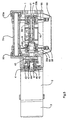
- the device has a housing 1.
- One first servomotor 2, which simplifies the electronic Control 3 is indicated, is at its flange 4 flanged by bolts 5 on the housing 1.
- This first servomotor 2 is known per se Way controlled so that it intermittently intermittent Rotary movements executes. The duration and the Extent of each step of the rotary motion depending on the in the downstream press controlled to be performed processing.
- This servomotor 2 has a drive shaft 6.
- the harmonic 8, 9 with the upper feed roller 10 and the lower shaft 20, 21 with the lower feed roller 22 is arranged, which supplied to the band-shaped blank 7 usually a metal band, intermittently advance.
- the harmonic is in an axial servomotor side first shaft section 8 and one in one axial distance from this first shaft portion 8 arranged Servomotorfernen, second shaft section 9 divided. Between these shaft sections 8, 9 is a upper feed roller 10 kept clamped.
- the servomotor remote, second shaft section 9 is from a clamping screw 11 supported on it axially interspersed, with the servomotor side, first Shaft section 8 is in screw engagement.
- This upper feed roller 10 which consists of several Parts exists and is very lightly constructed, rejects the Shape of a hollow circular cylinder with an axial interior 12 with an inner peripheral wall 13 and two end surface portions 14 and 15 on. See Figure 3.
- the transition region 16 between the end surface portion 14 and the inner peripheral wall 13 of the inner space 12 has the shape of a truncated cone shell.
- the transition region 17 between the End surface portion 15 and the inner peripheral wall 13 of the Interior 12 the shape of a Kegelstumpfmahtels.
- the mutually facing ends of the shaft sections 8, 9 also have a truncated cone-shaped Sections 18 and 19, respectively.
- the lower shaft 20, 21 is also in one axial servo motor side, first shaft portion 20 and one at an axial distance from this first shaft portion 20 arranged remote servomotor, second shaft portion 21 split. Between these shaft sections 20, 21, the lower feed roller 22 is clamped held.
- the servomotor remote, second shaft section 21 is of a clamping screw supported on it 23 axially interspersed, with the servomotor side, first Shaft section 20 is in screw engagement.
- This lower feed roller 22 which consists of several Parts exists and is very lightly constructed, rejects the Shape of a hollow circular cylinder with an axial interior 24 with an inner peripheral wall 25 and two end surface portions 26 and 27 on.
- transition region 28 between the end surface portion 26 and the inner peripheral wall 25 of the inner space 24 has the shape of a truncated cone shell.
- transition region 29 between the End surface portion 27 and the inner peripheral wall 25 of the Interior 24 the shape of a truncated cone mantle.
- the mutually facing ends of the shaft sections 20, 21 also have a truncated cone-shaped Section 30 or 31.
- the servo motor side, first section 8 of Harmonic and the servo motor side first section 20 the lower shaft remain in place, such as in of Figure 2 is shown. So they will not be moved.
- the servo motor remote, second section 9 of the harmonic and the servo motor remote second portion 21 of the lower shaft are in dissolved clamping screws 11, 23 in the direction the arrow C has been moved axially. This is the lie Feed rollers 10, 22 free and can be removed from the waves become. It should be noted that in the figure 3 the axial distances of the components exaggerated drawn large are. The free space between the respective sections, that is their distance must be so large be that the rollers for removal in the radial direction can be moved freely.
- the servo motor side, first section 8 of the harmonic is about a roller bearing 32 in a later to be described Rocker 33, i. the swing section 33a stored.
- the lubricant space of the rolling bearing 32 is by means of Seals 34a, 34b sealed.
- the servomotor remote, second section 9 of Harmonic is about rolling bearings 35 in the swing section 33b stored.
- the lubricant space of the rolling bearing 35 is by means of Seals 36a, 36b sealed.
- the servo motor side, first section 20 of the Lower shaft is mounted on a rolling bearing 36 in the housing 1.
- the lubricant space of the rolling bearing 36 is by means of a seal 37 sealed.
- the servomotor remote, second section 21 of Lower shaft is mounted on roller bearings 38 and 92 in the housing 1.
- the lubricant space of the rolling bearing 38 is by means of Seals 39a, 39b sealed.
- a first preferred embodiment is the stored in the rocker 33 harmonic, the means exactly that stored in the swing section 33a Servomotor side, first shaft section 8 of the harmonic in drive connection with the first servomotor 1.
- the first shaft section 8 is provided with a Oldham coupling 40 is connected, of which in Fig. 7b the cross-plate 41 is shown separately.
- This Oldham clutch 40 is necessary because the first shaft section 8 (and obviously all associated with him Parts of the device) transverse movements relative to the stationary Drive shaft 6 of the servomotor 2 performs.
- This Oldham clutch 40 is of an upper Spur gear 42 followed, with a lower spur gear 43 meshes, which with the servomotor side, first Shaft portion 20 of the lower shaft is connected.
- connection of the upper spur gear 42 with the drive shaft 6 of the servomotor 2 is performed by a multi-part clamping sleeve with a first clamping sleeve part 44 and a second clamping sleeve part 45.
- clamping sleeve parts 44, 45 take place by means of ring clamping elements 46th
- the clamping screws are indicated by the reference numeral 47.
- the upper spur gear 42 is integral with formed the second clamping sleeve part 45, whereby a considerable savings in moving masses is achieved.
- the servomotor is close Part of the Oldham clutch also in one piece with formed the second clamping sleeve part 45.
- a still further preferred embodiment is in Figures 8, 9, 9a shown.
- the top roller 10 is frictionally engaged with the metal band rotates.
- the servo motor side second shaft portion 20 of the lower shaft from the servomotor 2 driven.
- this shaft section 20 formed integrally with the second clamping sleeve part 45, so again there is a minimum rotating mass.
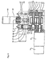
- a further servomotor 48 On a threaded spindle housing 67 is a further servomotor 48 arranged. His electronic Control, i. whose housing is indicated at 49.
- This servomotor 48 serves to drive a Threaded spindle 50.
- the servomotor 48 is merely an example to consider the drive of the threaded spindle 50. It can also 48 different drives from the servo motor to be available.
- the drive shaft of the servomotor 48 is indicated by the reference numeral 51.
- the connection between the drive shaft 51 of the servo motor 48 and the threaded spindle 50 takes place by means of a multipart clamping sleeve, a first clamping sleeve part 52, a second Clamping sleeve part 53 and ring clamping elements 54 has.
- the Clamping sleeve parts 52, 53 are by means of clamping screws 55 curious against each other.
- the second clamping sleeve part 53 is over a Claw clutch 113 connected to the threaded spindle 50.
- the threaded spindle 50 is in turn via rolling bearings 56 and 112 mounted in the threaded spindle housing 67 or housing 1.
- the threaded spindle 50 is independent stored free of play by the servo motor 48.
- ring clamping elements for connection Serve with the smooth motor shaft, can be a standard Servomotor, so no custom made used become.
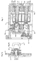
- This adjusting nut 57 On this adjusting nut 57 is a double-armed Lever 93 with a first arm 94 and a second Arm 95 stored.
- This lever 93 is in the present Description text referred to as the second double-armed lever 93.
- Adjusting nut 57 has a square cross-sectional shape and in a likewise a square cross-sectional shape having interior of the first double-armed Lever 93 is inserted. This is the adjusting nut 57 secured against twisting.
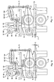
- This connecting rod 96 is seated on an eccentric disc 97, which via a shaft 98 with a third drive motor 99, for example, a servo motor, drivingly connected is.
- the control of the drive motor is indicated by the reference numeral 100.
- the second arm 95 of the first double-armed Lever 93 is a tab 101 on the first arm 102 of a hinged second double-armed lever 103.
- the second double-armed lever 103 is mounted on a shaft 60.
- the second arm 104 of the second double-armed lever 103 is fork-shaped, as in FIGS. 4 with the fork levers designating reference numerals 65, 66th is shown.
- the shaft 60 is in the threaded spindle housing 67th sealed by means of seals 61, 62 oil-tight, so that a closed threaded spindle housing 67 as a closed Lube space is present in which the threaded spindle 50 and the components described maintenance are arranged in a closed space.
- fork levers 65 and 66 are about a Ball-head connection to an upper shaft portion 68 or 69 one generally designated 70, and 71, respectively Control rod articulated, with lower shank sections 72 and 73 are screwed.
- the described shaft sections are by means of lock nuts 74 and 75 against a Twisting secured.
- the control rods are at their lower end hinged to the rocker 33.
- the rocker 33 in which the upper feed roller 10 is stored at its other end connected to a shaft 79.
- This shaft 79 is in the housing 1 stored.
- the bearings 80, 80a are in FIG. 5 located.
- the rocker 33 is by compression springs 83, 84th clamped against the lower feed roller 22.
- the contact pressure of the compression springs 83, 84 is by means of threaded spindles 85, 86 and lock nuts 87, 88, which are supported on the threaded spindle housing 67, set.
- the feed device described is to determines a ribbon-shaped blank 7, e.g. a metal band 7, one with tools for intermittent editing fed to the belt-shaped blank equipped press.
- the punch press 76 has a drive 77 on.
- This drive 77 can, as the expert in general is known to comprise an electric motor having a Crankshaft or a shaft with eccentric discs has.
- This crankshaft or eccentric disc is in Drive connection with a connecting rod 78.
- a ram 105 is articulated.
- the ram 105 carries an upper tool 106, thus in the operation of the punch press 76 is moved up and down.
- the upper tool 106 is compatible with processing tools, e.g. Stamp 107 equipped.
- control devices 49, 110 of the feed device and the punch press 76 communicate with each other, since the operation of the feed device matched to the operation of the punch press 76 have to be.
- the positions of the schematic parts of the feed device shown shown in continuous operation Rotate in continuous operation the upper feed roller 10 and the lower feed roller 22, which are driven by the servo motor 2 ago intermittently, so that the band-shaped blank 7 as general is known to be progressively advanced.
- the Punching press 76 has a moving upper tool 106 and a fixed lower tool 110.
- the upper tool 106 is connected to a plunger 105.
- the pestle 105 is driven by a rotary drive 77, e.g. electric motors and crankshaft or eccentric shaft, via a connecting rod 78 driven, the connecting rod 78 purely schematically the Drive connection between the drive 77 and the plunger 105 represents.
- the plunger is between an upper Tot Vietnamese ein and a bottom dead center position.bewegbar.
- the thickness of the strip-shaped blank 7 and according to the distance between the upper feed roller 10 and the lower feed roller 22 is in the Figure 10 with the letter E shown.
- the upper feed roller 10 To be able to, the upper feed roller 10 must be raised be so that they have a given distance D from the lower feed roller 22 which is larger than the Distance E is. This distance D and the lifted Position of the upper feed roller 10 are in the figure 11th shown.
- This position of the feed roller 10 is in the professional world referred to as Hochlcombposition.
- the bolt 58 is due to the of the Compression springs 82, 84 via the rocker 33 and the lever devices 93 and 103 at the lower end of the slot 59 at.
- Adjusting nut 57 By the downward movement of the Adjusting nut 57 is the first arm 94 of the first double-armed Lever 93 pivoted up and her second arm 95 pivoted down. This second arm 95 pulls the first arm 102 of the second double-armed lever device 103 also down. Thus, the second arm 104 of the second double-armed lever device 103 pivoted upwards. Consequently, the control rod assembly 68-75 lifted and thus the rocker 33 with the upper feed roller 10 mounted therein Hochlrangeposition the upper feed roller 10 pivoted in which they the said distance D from the lower Feed roller 22, so that a new band-shaped Blank 7 can be inserted.
- the upper feed roller must 10 rest on the band-shaped blank 7, wherein through the upper feed roller 10 and the lower feed roller 22 a clamping force for a frictional engagement on the strip-shaped blank 7 must be exercised.
- This clamping force is due to the compression springs 83, 84 generated. So the bolt 58 is not allowed to open anymore the lower end of the slot 59 rest. This will be the adjusting nut 57 by rotating the threaded spindle 50 lowered from the high ventilation position until the upper Feed roller 10 rests on the band-shaped blank 7. By a continued lowering movement of the adjusting nut 57, the first double-armed lever 93 is forced one To perform pivoting movement, since the rocker is not moves more because the upper feed roller 10 through the Compression springs 83, 84 resting on the band-shaped blank 7 is held.
- the said pivoting movement causes that the first arm 94 with the bolt 58 upwards pivots, so that the bolt 58 in the running hole 59 between whose ends are located. That means that the connecting rod 96 can perform strokes, without that an action on the bolt 58 takes place.
- This Eisenlstructure ein is by the Connecting rod 96 causes.
- the punch press 76 is in the stroke position driven, in which the intermediate ventilation takes place should and in which position the conical head sections 109 of the catching pins 108 partially in the positioning holes retracted. This position can be seen in FIG.
- the connecting rod 96 of the feeding device is now at the same time by the actuation of its drive motor 99 in a position before its top dead center position moved up.
- This angular position and the top dead center also an angular distance available.
- the one mentioned in connection with the punch press Angular distance is equal to that of the feed device existing angular distance.
- the adjusting nut 57 by rotating the threaded spindle 50 moves downward. This comes the bolt 58 to rest against the lower end of the slot 59. The adjusting nut 57 is then further down moves, so that due to the now occurring pivoting movements the lever devices and the rocker 33 the upper feed roller 10 releases the band-shaped blank. In this released state of the band-shaped blank manually detectable loose. This position of the adjusting nut 57 becomes along with the respective angular positions stored in the control devices 49 and 111.
Landscapes
- Engineering & Computer Science (AREA)
- Mechanical Engineering (AREA)
- Press Drives And Press Lines (AREA)
- Advancing Webs (AREA)
Abstract
Description
Die vorliegende Erfindung betrifft eine Vorschubvorrichtung zum intermittierenden Zuführen eines bandförmigen Rohlings zu einer mit Werkzeugen zum intermittierenden Bearbeiten des bandförmigen Rohlings ausgerüsteten Presse, welche Vorschubvorrichtung ein Gehäuse und ein auf dem Gehäuse angeordnetes Gewindespindelgehäuse, eine auf einer Oberwelle angeordnete obere Vorschubwalze und eine auf einer Unterwelle angeordnete untere Vorschubwalze aufweist, welche Vorschubwalzen dazu bestimmt sind, den zuzuführenden Rohling durch ein beidseitiges Klemmen zu ergreifen und durch eine intermittierende Rotationsbewegung intermittierend vorzuschieben, von welchen Wellen mindestens eine mit einem intermittierend arbeitenden elektrischen Servomotor antriebsverbunden ist und die Oberwelle in einer über eine Schwingenwelle am Gehäuse angelenkten Schwinge gelagert ist, mittels welcher sie gegen die Unterwelle und von derselben weg bewegbar ist.The present invention relates to a feed device for intermittently supplying a band-shaped blank to one with tools for intermittent Editing the band-shaped blank equipped Press, which feed device a housing and a threaded spindle housing arranged on the housing, a arranged on a harmonic upper feed roller and a lower shaft disposed on a lower shaft Feed roller having which feed rollers intended are, the supplied blank by a two-sided To seize terminals and through an intermittent To advance rotational movement intermittently, by which waves at least one with an intermittent working electric servomotor is drivingly connected and the harmonic in one over a swinging shaft at the Housing hinged rocker is mounted by means of which they move against the lower shaft and away from it is.
Die Erfindung betrifft weiter ein Verfahren zum Betrieb der eingangs genannten Vorschubvorrichtung, welche Vorschubvorrichtung eine Steuervorrichtung aufweist und mit einer Presse zusammenwirkt, die ein bewegtes Oberwerkzeug und ein feststehendes Unterwerkzeug aufweist, welches Oberwerkzeug mit einem zwischen einer oberen Totpunktstellung und einer unteren Totpunktstellung bewegbaren Stössel verbunden ist, und die eine Pressensteuerung aufweist, die mit der Steuervorrichtung der Vorschubvorrichtung in Verbindung steht, und bei welchem das Langloch des zwischen einer oberen Totpunktstellung und einer unteren Totpunktstellung bewegbaren Pleuels ein oberes und ein unteres Ende aufweist, der erste Arm der zweiten doppelarmigen Hebelvorrichtung über ein das Langloch durchsetzenden Bolzen im Eingriff mit dem Pleuel steht, wobei zum Einführen eines neuen bandförmigen Rohlings zwischen der oberen Vorschubwalze und der unteren Vorschubwalze die obere Vorschubwalze in eine Hochlüftposition gefahren wird, um in dieser Position einen vorgegebenden Abstand zwischen der oberen Vorschubwalze und der unteren Vorschubwalze festzulegen.The invention further relates to a method for operation of the aforementioned feed device, which feed device has a control device and interact with a press that is a moving one Upper tool and has a fixed lower tool, which upper tool with one between an upper Dead center position and a bottom dead center position movable plunger is connected, and the one press control having, with the control device of Feed device is connected, and in which the slot of between a top dead center position and a bottom dead center position movable connecting rod has upper and a lower end, the first arm of the second double-armed lever device via a slot passing bolts in engagement with the connecting rod stands, wherein for introducing a new band-shaped blank between the upper feed roller and the lower feed roller Feed roller, the upper feed roller in a high-lift position is driven to give a pre-eminent position in this position Distance between the upper feed roller and the set lower feed roller.
Weiter betrifft die Erfindung ein Verfahren zum Betrieb der Vorschubvorrichtung der eingangs genannten Art, bei welchem die Vorschubvorrichtung eine Steuervorrichtung aufweist und mit einer Presse zusammenwirkt, die ein bewegtes Oberwerkzeug und ein feststehendes Unterwerkzeug aufweist, welches Oberwerkzeug mit einem zwischen einer oberen Totpunktstellung und einer unteren Totpunktstellung bewegbarer Stössel verbunden ist, und die eine Pressensteuervorrichtung aufweist, die mit der Steuervorrichtung der Vorschubvorrichtung in Verbindung steht, und bei welchem das Langloch des zwischen einer oberen Totpunktstellung und einer unteren Totpunktstellung bewegbaren Pleuel ein oberes und ein unteres Ende aufweist, der erste Arm einer ersten doppelarmigen Hebelvorrichtung über einen das Langloch durchsetzender Bolzen im Eingriff steht. Furthermore, the invention relates to a method for operating the feed device of the aforementioned Type in which the feed device is a control device and cooperates with a press, a moving upper tool and a fixed lower tool has, which upper tool with an intermediate a top dead center position and a bottom dead center Totpunktstellung movable plunger is connected, and having a press control device, with the Control device of the feed device in connection stands, and in which the slot of between a top dead center position and a bottom dead center position movable connecting rod an upper and a lower end comprising the first arm of a first double-armed lever device via a bolt penetrating the slot is engaged.
Die Erfindung betrifft auch ein Verfahren zum Betrieb der Vorschubvorrichtung der eingangs genannten Art, bei welchem die Vorschubvorrichtung eine Steuervorrichtung aufweist und mit einer Presse zusammenwirkt, die ein bewegtes Oberwerkzeug und ein feststehendes Unterwerkzeug aufweist, welches Oberwerkzeug mit einem zwischen einer oberen Totpunktstellung und einer unteren Totpunktstellung bewegbarer Stössel verbunden ist, und die eine Pressensteuerung aufweist, die mit der Steuervorrichtung des Vorschubvorrichtung in Verbindung steht, und bei welcher das Langloch des zwischen einer oberen Totpunktstellung und einer unteren Totpunktstellung bewegbaren Pleuels ein oberes und ein unteres Ende aufweist, der erste Arm einen ersten doppelarmigen Hebelvorrichtung über einen das Langloch durchsetzenden Bolzen in Eingriff mit dem Pleuel steht, welcher Stössel von einem rotierenden Antrieb getrieben ist und die Exzenterscheibe des Pleuels von einem Antriebsmotor getrieben ist, welches Oberwerkzeug Fangstifte zum präzisen Positionieren des bandförmigen Rohling in der Presse während dem Bearbeitungsvorgang desselben aufweist, welche Fangstifte in vorgestanzte Positionierlöcher im bandförmigen Rohling hineinbewegt werden, welche Fangstifte einen konischen Kopfabschnitt aufweisen, wobei die obere Vorschubwalze dann von der unteren Vorschubwalze weg in eine Zwischenlüfterstellung aufwärts bewegt wird, wenn die konischen Kopfabschnitte teilweise in die Positionierlöcher eingefahren worden sind und danach wieder auf den Rohling abgesetzt wird, wenn die konischen Kopfabschnitte teilweise aus den Positionslöchern ausgehoben worden sind.The invention also relates to a method for Operation of the feed device of the aforementioned Type in which the feed device is a control device and cooperates with a press, the a moving upper tool and a fixed lower tool has, which upper tool with an intermediate a top dead center position and a bottom dead center Totpunktstellung movable plunger is connected, and having a press control associated with the control device the feed device is in communication, and in which the slot of the between an upper Dead center position and a bottom dead center position movable Pleuels has an upper and a lower end, the first arm has a first double-armed lever device via a bolt passing through the slot in Engage with the connecting rod, which ram of one driven by rotating drive and the eccentric disc of the connecting rod is driven by a drive motor, which Upper tool Cutter pins for precise positioning the band-shaped blank in the press during the machining process the same, which pegs in pre-punched positioning holes in the band-shaped blank are moved into which pins a conical Head section, wherein the upper feed roller then away from the lower feed roller into an intermediate fan position is moved upward when the conical Head sections partially retracted into the positioning holes have been and then dropped off again on the blank is when the conical head sections partially have been dug out of the position holes.
Die hier angesprochenen Pressen sind insbesondere schnelllaufende Pressen mit Hubzahlen bis zu 2000 Hübe/Minute. Diese Pressen sind mit Werkzeugen zur Bearbeitung eines (oder mehreren) zugeführten bandförmigen Rohlings ausgerüstet, wobei Stanzarbeiten, Prägearbeiten, Biegearbeiten, ein Vernieten, ein Herstellen von Gewinden, etc. durchgeführt werden.The presses mentioned here are in particular high-speed presses with stroke rates up to 2000 Strokes / minute. These presses are equipped with tools for machining one (or more) supplied band-shaped Blank, with punching, embossing, Bending, riveting, threading, etc. are performed.
Die Bewegung des bandförmigen Rohlings, der in der Presse bearbeitet wird, erfolgt dabei intermittierend, also schrittweise. Während einem Bearbeitungsschritt, z.B. einem Stanzen, erfolgt offensichtlich keine Vorwärtsbewegung des bandförmigen Rohlings. Oft wird er durch in den Werkzeugen angeordnete Fangstifte genau positioniert, also arretiert. Nach der Beendigung des Bearbeitungsschrittes, nachdem beispielsweise ein Stanzwerkzeug aus dem durchgestanzten Loch herausbewegt worden ist, wird der bandförmige Rohling um eine vorgegebene Strecke vorgeschoben und wieder angehalten, so dass der nächstfolgende Bearbeitungsschritt durchgeführt werden kann.The movement of the band-shaped blank, the is edited in the press, takes place intermittently, so gradually. During a processing step, e.g. a punching, obviously no Forward movement of the band-shaped blank. Often he will precisely positioned by means of gripping pins arranged in the tools So arrested. After completion of the processing step, after, for example, a punching tool been moved out of the punched hole is, the band-shaped blank by a predetermined Route advanced and stopped again, so that the next processing step to be performed can.
Die Zufuhr- resp. Vorschubbewegung des bandförmigen Rohlings erfolgt durch einen (oder mehrere, beim Eintritt und beim Austritt der Presse angeordnete) Zufuhr- bzw. Vorschubapparat (bzw. Vorschubapparate), um den bandförmigen Rohling intermittierend von einer Vorratsrolle abzuziehen und der Presse zuzuführen. The feed resp. Feed movement of the band-shaped Blanks are made by one (or more, at Inlet and outlet of the press). or feed unit (or feed units) to the ribbon-shaped blank intermittently from a supply roll deduct and deliver to the press.
Diese Vorschubapparate weisen üblicherweise Vorschubglieder auf, um den bandförmigen Rohling vorzuschieben. Dabei wird dieser durch die Vorschubglieder geklemmt und vorwärts bewegt. Wenn die Vorschubglieder wieder in ihre Ausgangsposition zurückkehren, wird die Klemmung aufgehoben. Die Klemmung wird zusätzlich während derjenigen Zeitspanne kurzzeitig aufgehoben, während welcher die Werkzeuge am bandförmigen Rohling einen Bearbeitungsschritt durchführen, insbesondere im Fall von Fangstiften.These feeders usually have Feed links on to advance the ribbon-shaped blank. This is clamped by the feed members and moved forward. When the feed links again return to their original position, the clamping is canceled. The clamping is additionally during the period temporarily suspended during which the tools on the band-shaped blank a processing step perform, especially in the case of pegs.
Es sind Ausführungen von solchen Vorschubapparaten bekannt geworden, bei welchen die Klemmglieder als sich linear bewegende Klemmzangen ausgebildet sind. Andere Ausführungen weisen oszillierende, Drehbewegungen ausführende Segmentwalzen auf.There are versions of such feeders become known, in which the clamping members are formed as linearly moving clamps. Other versions have oscillating, rotational movements exporting segment rollers.
Auch sind Vorschubapparate mit elektrischen Servomotoren bekannt geworden. Dabei ist ein erster Servomotor dem Vorschubbetrieb der Klemmglieder und ein weiterer, zweiter Servomotor dem intermittierenden Abheben eines Klemmgliedes oder bandförmigen Rohling zugeordnet. Solche Servomotoren werden von mehreren Firmen hergestellt und verkauft. Der Betrieb dieser Servomotoren ist elektronisch gesteuert. Diese neuen Vorschubapparate weisen als Vorschubglieder vollständig zylinderförmige, auf Wellen angeordnete Vorschubwalzen auf, die intermittierend immer im gleichen Drehsinn rotieren. Von diesen Vorschubwalzen ist eine in einem mit dem weiteren Servomotor antriebsverbunden Bauteil gelagert, auf Grund dessen Betrieb diese Vorschubwalze gegen den bandförmigen Rohling zum Klemmen desselben und von ihm zur Freigabe wegbewegt wird.Also are feeders with electric Servo motors become known. Here is a first servomotor the feed operation of the clamping members and another, second servomotor the intermittent lifting associated with a clamping member or band-shaped blank. Such servomotors are manufactured by several companies and sold. The operation of these servomotors is electronically controlled. Show these new feeders as feed members completely cylindrical, on Shafts arranged feed rollers, which intermittently always rotate in the same direction. From these feed rollers is one in one with the other servomotor Driven connected component stored due to its operation this feed roller against the band-shaped blank for clamping it and moved away from it for release becomes.
Durch die gegenwärtigen hohen Hubzahlen spielen die Massen der bewegten Teile eines Vorschubapparates auf Grund der Trägheitskräfte und Trägheitsmomente eine grosse Rolle, und haben des weiteren einen grossen Einfluss auf die Präzision des hergestellten Produktes. Weiter muss die Anordnung und Ausbildung dieser bewegten Teile auf Grund der Zeitspannen zur Beschleunigung und Verzögerung von Bewegungen derart sein, dass ein Betrieb mit hohen Hubzahlen sicher durchgeführt werden kann.Play through the current high number of strokes the masses of moving parts of a feeder unit due to inertial forces and moments of inertia great role, and also have a big impact on the precision of the manufactured product. Further must move the arrangement and training of this Parts due to the time periods for acceleration and Delay of movements be such that an operation can be carried out safely with high stroke rates.
Es ist somit ein Ziel der vorliegenden Erfindung, eine Vorrichtung zum intermittierenden Zuführen eines bandförmigen Rohlings zu schaffen, die ein Minimum an bewegten Teilen aufweist, wobei diejenigen Teile, die hohen Beschleunigungen und Verzögerungen unterworfen sind, kleinstmögliche Massen aufweisen und keine Antriebsmotoren vorhanden sind, die oszillierend arbeiten.It is thus an object of the present invention a device for intermittently feeding a band-shaped blank to create the minimum moving parts, wherein those parts, the high Accelerations and delays are subject have the smallest possible masses and no drive motors are present, which work oscillatingly.
Ein weiteres Ziel ist eine Vorrichtung zu schaffen, bei welcher der Rahmen ein Gewindespindelgehäuse aufweist, in welchem die Gewindespindel angeordnet ist, welche Gewindespindel starr mit einem Hülsenteil verbunden ist, der über Wälzlager spielfrei im Gewindespindelgehäuse gelagert ist, so dass die Gewindespindel im Gewindespindelgehäuse spielfrei gelagert ist.Another goal is a device too create, in which the frame is a threaded spindle housing in which the threaded spindle is arranged is which threaded spindle rigid with a sleeve part is connected, the play on roller bearings in the threaded spindle housing is stored, so that the threaded spindle is stored in the threaded spindle housing without play.
Noch ein weiteres Ziel der Erfindung ist eine Vorrichtung zu zeigen, bei welcher der mit der Gewindespindel starr verbundene Hülsenteil Teil einer mehrteiligen Spannhülse ist, in welche die Antriebswelle des weiteren Servomotors hineinragt, so dass die Antriebswelle des weiteren Servomotors kraftschlüssig mit der Gewindespindel verbunden ist, womit beim Montieren des weiteren Servomotors durch ein Verbinden seiner Antriebswelle mit der Gewindespindel über die Spannhülse die endgültige Position des Servomotors durch die im Gewindespindelgehäuse präzis gelagerte Gewindespindel bestimmt wird. Yet another object of the invention is a Device to show in which the with the threaded spindle rigidly connected sleeve part of a multipart Clamping sleeve is, in which the drive shaft of the other Servomotor protrudes so that the drive shaft the other servo motor frictionally with the threaded spindle is connected, which when mounting the other Servomotor by connecting its drive shaft with the threaded spindle on the clamping sleeve the final position of the servo motor by the threaded spindle housing precisely mounted threaded spindle is determined.
Auch ist es ein weiteres Ziel der vorliegenden Erfindung ein Verfahren zum Betrieb der eingangs genannten Vorschubvorrichtung zu zeigen, bei welchem zur Einstellung der Hochlüftposition der oberen Vorschubwalze die genannten zwei Steuervorrichtungen derart gesteuert werden, dass der Stössel in seine untere Totpunktstellung und der Pleuel in seine obere Totpunktstellung gesteuert wird.Also, it is another objective of the present Invention a method of operation of the aforementioned Feed device to show in which the Setting the high-lift position of the upper feed roller controlling said two control devices be that the plunger in its bottom dead center position and the connecting rod is controlled to its top dead center position becomes.
Ein noch weiteres Ziel der Erfindung ist ein Verfahren zum Betrieb der eingangs genannten Vorschubvorrichtung zu schaffen, bei welchem der Pleuel in seine untere Totpunktstellung bewegt wird, die Verstellmutter durch ein Rotieren der Gewindespindel abwärts verschoben wird, bis die obere Vorschubwalze aufgrund der durch die Druckfedern auf die Schwinge ausgeübten Druck auf dem bandförmigen Rohling aufliegt, und danach die Verstellmutter weiter abwärts verschoben wird, bis der Bolzen von beiden Enden des Langloches einen Abstand aufweist, so dass Hubbewegungen des Pleuels bei feststehendem Bolzen ermöglicht sind.A still further object of the invention is a Method for operating the feed device mentioned above to create, in which the connecting rod in his lower Dead center position is moved, the adjusting nut moved downward by a rotation of the threaded spindle until the upper feed roller due to the. By the Compression springs on the swingarm exerted pressure on the band-shaped blank rests, and then the adjusting nut is moved downwards until the bolt of both ends of the slot has a distance, so that lifting movements of the connecting rod with a fixed bolt are possible.
Ein noch weiteres Ziel der Erfindung ist ein Verfahren zum Betrieb der Vorschubvorrichtung der eingangs genannten Art zu schaffen, bei welchem zur Einstellung der Zwischenlüftstellung der Stössel durch seinen rotierenden Antrieb in eine Winkelstellung vor seiner unteren Totpunktstellung gebracht wird, in welcher Winkelstellung die konischen Kopfabschnitte der Fangstifte nur teilweise in die Positionierlöcher hineinragen, und die Exzenterscheibe des Pleuels in eine Winkelstellung vor der oberen Totpunktstellung gebracht wird, wobei der Winkelabstand des Stössels zwischen der genannten Winkelstellung und der unteren Totpunktstellung gleich dem Winkelabstand der Exzenterscheibe zwischen ihrer genannten Winkelstellung und der oberen Totpunktstellung ist, danach die Gewindemutter nach unten bewegt wird, bis der bandförmige Rohling aufgrund des Abhebens der oberen Vorschubwalze lose ist, und dass die Position der Verstellmutter für die genannte Winkelstellung der Exzenterscheibe und die entsprechende Winkelstellung des Stössels in den entsprechenden Steuervorrichtungen gespeichert werden.A still further object of the invention is a Method for operating the feed device of the beginning to create type mentioned, in which the attitude the intermediate release position of the plunger by his rotating drive in an angular position in front of its lower Dead center position is brought, in which angular position the conical head sections of the fishing pins only partially protrude into the positioning holes, and the Eccentric disc of the connecting rod in an angular position the top dead center position is brought, the angular distance the plunger between said angular position and the bottom dead center position equal to the angular distance the eccentric disc between her Angular position and the top dead center is, then the nut is moved down until the strip-shaped blank due to the lifting of the upper feed roller is loose, and that the position of the adjusting nut for said angular position of the eccentric disc and the corresponding angular position of the plunger in the corresponding control devices are stored.
Auf Grund der Ausbildung der Spannhülse, die ein einstückiger Teil der Gewindespindel ist, besteht die Freiheit, unterschiedliche Servomotoren auszuwählen und zu montieren, und insbesondere genormte Standardmotoren, da keine speziell angefertigte Antriebswellen solcher Servomotoren notwendig sind. Due to the design of the clamping sleeve, the is an integral part of the threaded spindle, there is the Freedom to select different servomotors and to assemble, and in particular standardized standard motors, because no specially made drive shafts such Servo motors are necessary.
Die Ausbildung der Vorschubvorrichtung muss
grundsätzlich 3 Hauptfunktionen erfüllen, nämlich die
Hochlüftung (Band einschieben), die Banddickeneinstellung
(die obere Walze liegt auf dem Band, Spiel im Langloch
des Pleuels) und Zwischenlüftung (Bandlüftung vor jedem
Stanzvorgang). Diese Ziele werden durch eine Vorschubvorrichtung gemäß Anspruch 1 bzw. durch
ein Verfahren zum Betrieb dieser Vorschubvorrichtung gemäß den Ansprüchen
8, 10 und 11 erreicht. Die abhängigen Ansprüche stellen bevorzugte
Ausführungsbeispiele der Vorschubvorrichtung bzw. des Verfahrens der Erfindung dar.The formation of the feed device must
basically fulfill 3 main functions, namely the
High ventilation (insert belt), the belt thickness adjustment
(the upper roller lies on the tape, play in the slot
of the connecting rod) and intermediate ventilation (ventilation before each
Punching process). These objects are achieved by a feed device according to
Nachfolgend wird der Gegenstand der Erfindung
anhand von Ausführungsbeispielen zeigenden Zeichnungen
näher erläutert. Es zeigt:
Die Vorrichtung weist ein Gehäuse 1 auf. Ein
erster Servomotor 2, von welchem vereinfacht die elektronische
Steuerung 3 angedeutet ist, ist bei seinem Flansch
4 über Schraubbolzen 5 am Gehäuse 1 angeflanscht.The device has a
Dieser erste Servomotor 2 ist in an sich bekannter
Weise derart gesteuert, dass er schrittweise intermittierende
Drehbewegungen ausführt. Die Dauer und das
Ausmass eines jeweiligen Schrittes der Drehbewegung werden
abhängig von der in der nachgeschalteten Presse
durchzuführenden Bearbeitung gesteuert. Dieser Servomotor
2 weist eine Antriebswelle 6 auf.This
Im Gehäuse 1 sind die Oberwelle 8, 9 mit der
oberen Vorschubwalze 10 und die Unterwelle 20, 21 mit der
unteren Vorschubwalze 22 angeordnet, welche den zuzuführenden
bandförmigen Rohling 7 üblicherweise ein Metallband,
intermittierend vorschieben.In the
Die Oberwelle ist in einen axial servomotorseitigen
ersten Wellenabschnitt 8 und einen in einem
axialen Abstand von diesem ersten Wellenabschnitt 8 angeordneten
servomotorfernen, zweiten Wellenabschnitt 9 aufgeteilt.
Zwischen diesen Wellenabschnitten 8, 9 ist eine
obere Vorschubwalze 10 geklemmt gehalten.The harmonic is in an axial servomotor side
Der servomotorferne, zweite Wellenabschnitt 9
ist von einer sich auf ihm abstützende Spannschraube 11
axial durchsetzt, die mit dem servomotorseitigen, ersten
Wellenabschnitt 8 im Schraubeingriff steht.The servomotor remote,
Durch diese Spannschraube 11 sind die zwei
Wellenabschnitte 8, 9 gegeneinander gespannt, so dass die
zwischen diesen Wellenabschnitten 8, 9 angeordnete obere
Vorschubwalze 10 geklemmt gehalten ist.By this clamping
Diese obere Vorschubwalze 10, die aus mehreren
Teilen besteht und sehr leicht gebaut ist, weist die
Form eines hohlen Kreiszylinders mit einem axialen Innenraum
12 mit einer Innenumfangswand 13 und zwei Endflächenabschnitten
14 und 15 auf. Siehe Figur 3.This
Der Übergangsbereich 16 zwischen dem Endflächenabschnitt
14 und der Innenumfangswand 13 des Innenraumes
12 weist die Form eines Kegelstumpfmantels auf.
Gleicherweise weist der Übergangsbereich 17 zwischen dem
Endflächenabschnitt 15 und der Innenumfangswand 13 des
Innenraumes 12 die Form eines Kegelstumpfmahtels auf.The
Die einander zugekehrten Enden der Wellenabschnitte
8, 9 weisen ebenfalls einen kegelstumpfmantelförmigen
Abschnitt 18 bzw. 19 auf.The mutually facing ends of the
Es ist somit ersichtlich, dass nach erfolgtem
Anziehen der Spannschraube 11 die einander entsprechenden
kegelstumpfmantelförmigen Abschnitte 16, 18 bzw. 17, 19
aneinander anliegen, so dass die dazwischen angeordnete
obere Vorschubwalze 10 geklemmt und geführt gehalten ist.It can thus be seen that after completion
Tighten the clamping
Ebenfalls ersichtlich ist, dass zum Ausbauen
der oberen Vorschubwalze 10 lediglich die Spannschraube
11 gelöst und durch eine Öffnung im Gehäuse 1, durch welche
die Spannschraube 11 zugänglich ist, weggezogen werden
muss. Dann kann die Vorschubwalze ohne weiteres ausgebaut
werden.It is also evident that to remove
the
Dieser Zustand ist rein beispielsweise im Zusammenhang
mit den noch zu beschreibenden unteren Wellenabschnitten
20, 21 und der unteren Vorschubwalze 22 in
der Figur 3 dargestellt. Die axialen Abstände, auf die
noch eingegangen wird, sind übertrieben gross dargestellt.This condition is purely related, for example
with the lower shaft sections to be described later
20, 21 and the
Die Unterwelle 20, 21 ist ebenfalls in einem
axial servomotorseitigen, ersten Wellenabschnitt 20 und
einen in einem axialen Abstand von diesem ersten Wellenabschnitt
20 angeordneten servomotorfernen, zweiten Wellenabschnitt
21 aufgeteilt. Zwischen diesen Wellenabschnitten
20, 21 ist die untere Vorschubwalze 22 geklemmt
gehalten.The
Der servomotorferne, zweite Wellenabschnitt
21 ist von einer sich auf ihm abstützenden Spannschraube
23 axial durchsetzt, die mit dem servomotorseitigen, ersten
Wellenabschnitt 20 im Schraubeingriff steht.The servomotor remote,
Durch diese Spannschraube 23 sind die zwei
Wellenabschnitte 21, 22 gegeneinander gespannt, so dass
die zwischen diesen Wellenabschnitten 21, 22 angeordnete
untere Vorschubwalze 22 geklemmt gehalten ist.By this clamping
Diese untere Vorschubwalze 22, die aus mehreren
Teilen besteht und sehr leicht gebaut ist, weist die
Form eines hohlen Kreiszylinders mit einem axialen Innenraum
24 mit einer Innenumfangswand 25 und zwei Endflächenabschnitten
26 und 27 auf.This
Der Übergangsbereich 28 zwischen dem Endflächenabschnitt
26 und der Innenumfangswand 25 des Innenraumes
24 weist die Form eines Kegelstumpfmantels auf.
Gleicherweise weist der Übergangsbereich 29 zwischen dem
Endflächenabschnitt 27 und der Innenumfangswand 25 des
Innenraumes 24 die Form eines Kegelstumpfmantels auf.The
Die einander zugekehrten Enden der Wellenabschnitte
20, 21 weisen ebenfalls einen kegelstumpfmantelförmigen
Abschnitt 30 bzw. 31 auf.The mutually facing ends of the
Es ist somit ersichtlich, dass nach erfolgtem
Anziehen der Spannschraube 23 die einander entsprechenden
kegelstumpfmantelförmigen Abschnitte 28, 30 bzw. 29, 31
aneinander anliegen, so dass die dazwischen angeordnete
untere Vorschubwalze 22 geklemmt und geführt gehalten
ist.It can thus be seen that after completion
Tighten the clamping
Ebenfalls ersichtlich ist, dass zum Ausbauen
der unteren Vorschubwalze .22 lediglich die Spannschraube
23 gelöst und durch eine Öffnung im Gehäuse 1, durch welche
die Spannschraube 23 zugänglich ist, weggezogen werden
muss. Dann kann die Vorschubwalze 22 ohne weiteres
ausgebaut werden.It is also evident that to remove
the lower feed roller .22 only the clamping
Dieser Zustand ist in der Figur 3 dargestellt.This state is shown in FIG.
Der servomotorseitige, erste Abschnitt 8 der
Oberwelle und der servomotorseitige erste Abschnitt 20
der Unterwelle verbleiben an Ort, wie beispielsweise in
der Figur 2 gezeigt ist. Sie werden also nicht verschoben.
Der servomotorferne, zweite Abschnitt 9 der Oberwelle
und der servomotorferne zweite Abschnitt 21 der Unterwelle
sind bei gelösten Spannschrauben 11, 23 in Richtung
des Pfeiles C axial verschoben worden. Damit liegen die
Vorschubwalzen 10, 22 frei und können von den Wellen entfernt
werden. Zu bemerken ist, dass in der Figur 3 die
axialen Abstände der Bauteile übertrieben gross gezeichnet
sind. Der freie Raum zwischen den jeweiligen Abschnitten,
das heisst deren Abstand muss nur derart gross
sein, dass die Walzen zum Entnehmen in radialer Richtung
frei verschoben werden können.The servo motor side,
Es wird nun auf die Figuren 8 und 10 verwiesen.
Der servomotorseitige, erste Abschnitt 8 der Oberwelle
ist über ein Wälzlager 32 in einer noch zu beschreibenden
Schwinge 33, d.h. dem Schwingenabschnitt 33a
gelagert. Der Schmierstoffraum des Wälzlagers 32 ist mittels
Dichtungen 34a, 34b abgedichtet.Reference is now made to FIGS. 8 and 10.
The servo motor side,
Der servomotorferne, zweite Abschnitt 9 der
Oberwelle ist über Wälzlager 35 im Schwingenabschnitt 33b
gelagert. Der Schmierstoffraum des Wälzlagers 35 ist mittels
Dichtungen 36a, 36b abgedichtet.The servomotor remote,
Der servomotorseitige, erste Abschnitt 20 der
Unterwelle ist über ein Wälzlager 36 im Gehäuse 1 gelagert.
Der Schmierstoffraum des Wälzlagers 36 ist mittels
einer Dichtung 37 abgedichtet.The servo motor side,
Der servomotorferne, zweite Abschnitt 21 der
Unterwelle ist über Wälzlager 38 und 92 im Gehäuse 1 gelagert.
Der Schmierstoffraum des Wälzlagers 38 ist mittels
Dichtungen 39a, 39b abgedichtet.The servomotor remote,
Es ist also ersichtlich, dass sämtliche Lager
der Wellenabschnitte 8,9,20,21 in jeweils eigenen
Schmierstoff- bzw. Schmierölkammern angeordnet sind und
somit das oben erwähnten Ausbauen der Vorschubwalzen
10,22 ohne irgendwelches Öffnen von Schmierstoffkammern
durchführbar ist. Damit sind die entsprechenden Walzenwechsel
der Vorschubwalzen 10, 22, sehr einfach durchzuführen.So it is obvious that all bearings
the
Gemäss einer ersten bevorzugten Ausführung
steht die in der Schwinge 33 gelagerte Oberwelle, das
heisst genau, der im Schwingenabschnitt 33a gelagerte
servomotorseitige, erste Wellenabschnitt 8 der Oberwelle
in Antriebsverbindung mit dem ersten Servomotor 1.According to a first preferred embodiment
is the stored in the
Der erste Wellenabschnitt 8 ist mit einer
Oldham-Kupplung 40 verbunden, von welcher in der Fig. 7b
die Kreuzscheibe 41 separat dargestellt ist. Diese Oldham-Kupplung
40 ist notwendig, weil der erste Wellenabschnitt
8 (und offensichtlich alle mit ihm verbundene
Teile der Vorrichtung) Querbewegungen relativ zur ortsfesten
Antriebswelle 6 des Servomotors 2 durchführt.The
Diese Oldham-Kupplung 40 ist von einem oberen
Stirnzahnrad 42 gefolgt, das mit einem unteren Stirnzahnrad
43 kämmt, welches mit dem servomotorseitigen, ersten
Wellenabschnitt 20 der Unterwelle verbunden ist.This Oldham clutch 40 is of an
Die Verbindung des oberen Stirnzahnrades 42
mit der Antriebswelle 6 des Servomotors 2 erfolgt durch
eine mehrteilige Spannhülse mit einem ersten Spannhülsenteil
44 und einem zweiten Spannhülsenteil 45.The connection of the
Das Zusammenwirken der Spannhülsenteile 44,
45 erfolgt mittels Ringspannelementen 46. Die Spannschrauben
sind mit der Bezugsziffer 47 aufgezeigt. The interaction of the clamping
Das obere Stirnzahnrad 42 ist einstückig mit
dem zweiten Spannhülsenteil 45 ausgebildet, womit eine
beträchtliche Ersparnis an bewegten Massen erreicht wird.The
Als bevorzugte Ausführung ist der servomotornahe
Teil der Oldham-Kupplung ebenfalls einstückig mit
dem zweiten Spannhülsenteil 45 ausgebildet.As a preferred embodiment of the servomotor is close
Part of the Oldham clutch also in one piece with
formed the second
Gemäss einer weiteren bevorzugten Ausführung
sind keine Stirnzahnräder vorhanden, so dass die untere
Vorschubwalze 22 lediglich durch Reibeingriff mit dem Metallband
7 rotiert wird.According to another preferred embodiment
There are no spur gears, so the lower one
Eine noch weiter bevorzugte Ausführung ist in
der Figuren 8, 9, 9a dargestellt. Bei dieser Ausführung
wird die Oberwalze 10 durch Reibeingriff mit dem Metallband
rotiert.A still further preferred embodiment is in
Figures 8, 9, 9a shown. In this version
the
Bei dieser Ausführung ist der servomotorseitige
zweite Wellenabschnitt 20 der Unterwelle vom Servomotor
2 angetrieben. Dabei ist dieser Wellenabschnitt 20
einstückig mit dem zweiten Spannhülsenteil 45 ausgebildet,
so dass wiederum eine minimale rotierende Masse vorliegt.In this embodiment, the servo motor side
Auf einem Gewindespindelgehäuse 67 ist ein
weiterer Servomotor 48 angeordnet. Seine elektronische
Steuerung, d.h. deren Gehäuse ist mit 49 angedeutet.On a threaded
Dieser Servomotor 48 dient zum Antrieb einer
Gewindespindel 50.This
Der Servomotor 48 ist als lediglich ein Beispiel
des Antriebs der Gewindespindel 50 zu betrachten.
Es können auch vom Servomotor 48 verschiedene Antriebe
vorhanden sein. Die Antriebswelle des Servomotors 48 ist
mit der Bezugsziffer 51 angedeutet. Die Verbindung zwischen
der Antriebswelle 51 des Servomotors 48 und der Gewindespindel
50 erfolgt mittels einer mehrteiligen Spannhülse,
die einen ersten Spannhülsenteil 52, einen zweiten
Spannhülsenteil 53 und Ringspannelemente 54 aufweist. Die
Spannhülsenteile 52, 53 werden mittels Spannschrauben 55
gegeneinander gespannt. The
Der zweite Spannhülsenteil 53 ist über eine
Klauenkupplung 113 mit der Gewindespindel 50 verbunden.
Die Gewindespindel 50 ist ihrerseits über Wälzlager 56
und 112 im Gewindespindelgehäuse 67 bzw. Gehäuse 1 gelagert.The second
Somit ist die Gewindespindel 50 unabhängig
vom Servomotor 48 spielfrei gelagert.Thus, the threaded
Dadurch, dass Ringspannelemente zur Verbindung mit der glatten Motorwelle dienen, kann ein genormter Servomotor, also keine Spezialanfertigung, verwendet werden.Because of the fact that ring clamping elements for connection Serve with the smooth motor shaft, can be a standard Servomotor, so no custom made used become.
Auf der Gewindespindel 50 ist eine Verstellmutter
57 angeordnet.On the threaded
Auf dieser Verstellmutter 57 ist ein doppelarmiger
Hebel 93 mit einem ersten Arm 94 und einem zweiten
Arm 95 gelagert. Dieser Hebel 93 wird im vorliegenden
Beschreibungstext als zweiter doppelarmiger Hebel 93 bezeichnet.On this adjusting
Aus der Figur 4 ist ersichtlich, dass die
Verstellmutter 57 eine quadratische Querschnittsform aufweist
und in einem ebenfalls eine quadratische Querschnittsform
aufweisenden Innenraum des ersten doppelarmigen
Hebels 93 eingesetzt ist. Damit ist die Verstellmutter
57 gegen ein Verdrehen gesichert.From Figure 4 it can be seen that the
Adjusting
Im ersten Arm 94 eines ersten doppelarmigen
Hebels 93 ist ein Bolzen 58 eingesetzt. Dieser Bolzen 58
ragt durch ein Langloch 59 in einem Pleuel 96.In the
Dieser Pleuel 96 sitzt auf einer Exzenterscheibe
97, die über eine Welle 98 mit einem dritten Antriebsmotor
99, beispielsweise einem Servomotor, antriebsverbunden
ist. Die Steuerung des Antriebsmotors ist
mit der Bezugsziffer 100 aufgezeigt.This connecting
Der zweite Arm 95 des ersten doppelarmigen
Hebels 93 ist über eine Lasche 101 am ersten Arm 102 eines
zweiten doppelarmigen Hebels 103 angelenkt. Der zweite
doppelarmige Hebel 103 ist auf einer Welle 60 gelagert.
Der zweite Arm 104 des zweiten doppelarmigen Hebels
103 ist gabelförmig ausgebildet, wie in den Figuren 4
mit den die Gabelhebel bezeichnenden Bezugsziffern 65, 66
aufgezeigt ist.The
Die Welle 60 ist im Gewindespindelgehäuse 67
mittels Dichtungen 61, 62 öldicht abgedichtet, so dass
ein geschlossenes Gewindespindelgehäuse 67 als geschlossener
Schmierölraum vorhanden ist, in welchem die Gewindespindel
50 und die beschriebenen Bauteile wartungsfrei
in einem geschlossenen Raum angeordnet sind.The
Insbesondere ist aus der Figur 4 ersichtlich,
dass die Welle 60 bei beiden Enden aus dem Gewindespindelgehäuse
67 hinausragt und dass die Gabelhebel 65, 66
auf den hinausragenden Enden aufgeklemmt sind.In particular, it can be seen from FIG. 4
that the
Diese Gabelhebel 65 bzw. 66 sind über eine
Kugelkopfverbindung an einem oberen Schaftabschnitt 68
bzw. 69 einer allgemein mit 70, bzw. 71 bezeichneten
Steuerstange angelenkt, die mit unteren Schaftabschnitten
72 bzw. 73 verschraubt sind. Die beschriebenen Schaftabschnitte
sind mittels Kontermuttern 74 bzw. 75 gegen ein
Verdrehen gesichert.These fork levers 65 and 66 are about a
Ball-head connection to an
Die Steuerstangen sind bei ihrem unteren Ende
an der Schwinge 33 angelenkt.The control rods are at their lower end
hinged to the
Die Schwinge 33, in welcher die obere Vorschubwalze
10 gelagert ist, ist bei ihrem anderen Ende
mit einer Welle 79 verbunden. Diese Welle 79 ist im Gehäuse
1 gelagert. Die Lager 80, 80a sind in der Figur 5
eingezeichnet.The
Es ist somit ersichtlich, dass die Schwinge
33 mit der darin gelagerten oberen Vorschubwalze 10 um
die Welle 79 erfolgende Schwenkbewegungen durchführen
kann. Damit kann die obere Vorschubwalze 10 gegen die untere
Vorschubwalze 22 mit dem sich darauf befindlichen
Metallband 7, welches in Richtung des Pfeiles B vorgeschoben
wird, und gegen dieses und von diesem weg bewegt
werden.It is thus apparent that the
In der Figur 6 sind zusätzlich der Bandeinlauftisch
81 und der Bandauslauftisch 82 eingezeichnet,
auf welchen Tischen das Metallband 7 beidseitig der unteren
Vorschubwalze 22 aufliegt.In the figure 6 are also the tape inlet table
81 and the tape outlet table 82 drawn,
on which tables the
Die Schwinge 33 ist durch Druckfedern 83, 84
gegen die untere Vorschubwalze 22 gespannt.The
Der Anpressdruck der Druckfedern 83, 84 wird
mittels Gewindespindeln 85, 86 und Kontermuttern 87, 88,
die sich auf dem Gewindespindelgehäuse 67 abstützen, eingestellt.The contact pressure of the compression springs 83, 84 is
by means of threaded
Das Einstellen des Anpressdruckes erfolgt mit
Hilfe eines Ablesens der Position der auf den Druckfedern
83, 84 aufliegenden Scheiben 89, 90 an der Skala 91. Offensichtlich
ist bei den Druckfedern 83, 84 je eine Skala
zugeordnet.The adjustment of the contact pressure is carried out with
Help of reading the position of the on the compression springs
83, 84 resting
Die beschriebene Vorschubvorrichtung ist dazu
bestimmt, einen bandförmigen Rohling 7, z.B. ein Metallband
7, einer mit Werkzeugen zum intermittierenden Bearbeiten
des bandförmigen Rohlings ausgerüsteten Presse zuzuführen.The feed device described is to
determines a ribbon-shaped blank 7, e.g. a
In der Figur 13 sind diese Vorschubvorrichtung
und die ihr zugeordnete Presse 76, eine Stanzpresse,
schematisch aufgezeichnet.In the figure 13, these feed device
and its associated
Die Stanzpresse 76 weist einen Antrieb 77
auf. Dieser Antrieb 77 kann, wie es dem Fachmann allgemein
bekannt ist, einen Elektromotor aufweisen, der eine
Kurbelwelle oder eine Welle mit Exzenterscheiben aufweist.
Diese Kurbelwelle oder Exzenterscheibe steht in
Antriebsverbindung mit einem Pleuel 78. An diesem Pleuel
78 ist ein Stössel 105 angelenkt. Der Stössel 105 trägt
ein Oberwerkzeug 106, das folglich im Betrieb der Stanzpresse
76 auf- und abbewegt wird. Das Oberwerkzeug 106
ist mit Bearbeitungswerkzeugen, z.B. Stempel 107 ausgerüstet.
Weiter ist das Oberwerkzeug 106 mit Fangstiften 108
ausgerüstet, welche jeweils einen konischen Kopfabschnitt
109 aufweisen.The
Wie allgemein bekannt ist, werden in Betrieb
vor dem Auftreffen der Bearbeitungswerkzeuge, also z.B.
der Stempel 107 auf dem bandförmigen Rohling 7 für.die
eigentliche Bearbeitung die Fangstifte 108 in vorgestanzte
Löcher im Rohling 7 hineinbewegt, um diesen präzise zu
zentrieren. Dabei ist die obere Vorschubwalze 10 von der
unteren Vorschubwalze 22 kurzzeitig um eine kleine Strekke
abgehoben, so dass keine Klemmkraft auf den bandförmigen
Rohling 7 ausgeübt wird. Diese Position der oberen
Vorschubwalze 10 wird als Zwischenlüftstellung bezeichnet.As is well known, are in operation
before impacting the processing tools, e.g.
the
Weiter sind in der Figur 13 das feststehende
Unterwerkzeug 110 und die Steuervorrichtung 111 der
Stanzpresse 76 eingezeichnet.Further, in FIG. 13, the fixed one
Es ist ersichtlich, dass die Steuervorrichtungen
49, 110 der Vorschubvorrichtung und der Stanzpresse
76 miteinander kommunizieren, da der Betrieb der Vorschubvorrichtung
auf den Betrieb der Stanzpresse 76 abgestimmt
sein muss.It can be seen that the
In der Figur 10 sind die Stellungen der schematisch
dargestellten Teile der Vorschubvorrichtung währen
dem Dauerbetrieb gezeigt. Im Dauerbetrieb rotieren
die obere Vorschubwalze 10 und die untere Vorschubwalze
22, die vom Servomotor 2 her angetrieben sind intermittierend,
so dass der bandförmige Rohling 7 wie allgemein
bekannt ist, schrittweise vorgeschoben wird. Dabei wirkt
die (elektronische) Steuervorrichtung 49 der Vorschubvorrichtung
mit der (elektronischen) Steuervorrichtung 111
einer Stanzpresse 76 zusammen, siehe hierzu Figur 13. Die
Stanzpresse 76 weist ein bewegtes Oberwerkzeug 106 und
ein feststehendes Unterwerkzeug 110 auf. Das Oberwerkzeug
106 ist mit einem Stössel 105 verbunden. Der Stössel 105
wird von einem rotierenden Antrieb 77, z.B. Elektromotoren
und Kurbelwelle oder Exzenterwelle, über einen Pleuel
78 angetrieben, wobei der Pleuel 78 rein schematisch die
Antriebsverbindung zwischen dem Antrieb 77 und dem Stössel
105 darstellt.In the figure 10, the positions of the schematic
parts of the feed device shown
shown in continuous operation. Rotate in continuous operation
the
Somit ist der Stössel zwischen einer oberen Totpunktstellung und einer unteren Totpunktstellung.bewegbar. Thus, the plunger is between an upper Totpunktstellung and a bottom dead center position.bewegbar.
Das Dickenmass des bandförmigen Rohlings 7
und entsprechend der Abstand zwischen der oberen Vorschubwalze
10 und der unteren Vorschubwalze 22 ist in der
Figur 10 mit dem Buchstaben E aufgezeigt.The thickness of the strip-shaped blank 7
and according to the distance between the
Um einen neuen bandförmigen Rohling 7, also
beispielsweise ein Metallband zwischen der oberen Vorschubwalze
10 und der unteren Vorschubwalze 22 einschieben
zu können, muss die obere Vorschubwalze 10 angehoben
werden, so dass sie einen vorgegebenen Abstand D von der
unteren Vorschubwalze 22 aufweist, der grösser als die
Distanz E ist. Dieser Abstand D und die hochgehobene
Stellung der oberen Vorschubwalze 10 sind in der Figur 11
dargestellt.To a new ribbon-shaped blank 7, ie
For example, a metal strip between the
Diese Stellung der Vorschubwalze 10 wird in
der Fachwelt als Hochlüftposition bezeichnet.This position of the
Zum Einstellen dieser Hochlüftposition werden
die Steuervorrichtungen 49 und 111 der Vorschubvorrichtung
und der Stanzpresse 76 derart betätigt, dass sich
der Stössel 105 der Stanzpresse von der unteren Totpunktstellung
entfernt befindet und dass sich der Pleuel 96
von der oberen Totpunktstellung entfernt befindet. In
welchen spezifischen Stellungen sich der Stössel 105 und
der Pleuel 96 befinden, ist unerheblich, solange sich der
Stössel nicht in der unteren Totpunktstellung befindet.
Allgemein, und dies ist dem Fachmann bekannt, werden jedoch
die Steuervorrichtungen 49 und 111 der Vorschubvorrichtung
und der Stanzpresse derart betätigt, dass sich
der Stössel 105 der Stanzpresse 76 in der oberen Totpunktstellung
befindet und dass sich der Pleuel 96 in der
unteren Totpunktstellung befindet. Die nun folgende Beschreibung
geht von diesen letzteren Totpunktstellungen
aus. Sind die genannten Totpunktstellungen erreicht, wird
die Verstellmutter 57 durch ein entsprechendes Rotieren
der Gewindespindel 50 abgesenkt.To set this high-lift position
the
Der Bolzen 58 liegt aufgrund der von den
Druckfedern 82, 84 über die Schwinge 33 und die Hebelvorrichtungen
93 und 103 am unteren Ende des Langloches 59
an.The
Durch die nach unten verlaufende Bewegung der
Verstellmutter 57 wird der erste Arm 94 der ersten doppelarmigen
Hebelvorrichtung 93 hochgeschwenkt und ihr
zweiter Arm 95 nach unten geschwenkt. Dieser zweite Arm
95 zieht den ersten Arm 102 der zweiten doppelarmigen Hebelvorrichtung
103 ebenfalls nach unten. Somit wird der
zweite Arm 104 der zweiten doppelarmigen Hebelvorrichtung
103 nach oben geschwenkt. Folglich wird die Steuerstangenanordnung
68-75 hochgehoben und damit die Schwinge 33
mit der darin gelagerten oberen Vorschubwalze 10 in die
Hochlüftposition der oberen Vorschubwalze 10 geschwenkt,
in welcher sie den besagten Abstand D von der unteren
Vorschubwalze 22 aufweist, so dass ein neuer bandförmiger
Rohling 7 eingeschoben werden kann.By the downward movement of the
Adjusting
Für den Dauerbetrieb muss die obere Vorschubwalze
10 auf dem bandförmigen Rohling 7 aufliegen, wobei
durch die obere Vorschubwalze 10 und die untere Vorschubwalze
22 eine Klemmkraft für einen Reibeingriff auf den
bandförmigen Rohling 7 ausgeübt werden muss.For continuous operation, the upper feed roller must
10 rest on the band-shaped blank 7, wherein
through the
Diese Klemmkraft wird durch die Druckfedern
83, 84 erzeugt. Also darf der Bolzen 58 nicht mehr auf
dem unteren Ende des Langloches 59 aufliegen. Dazu wird
die Verstellmutter 57 durch ein Rotieren der Gewindespindel
50 aus der Hochlüftstellung abgesenkt, bis die obere
Vorschubwalze 10 auf dem bandförmigen Rohling 7 aufliegt.
Durch eine fortgesetzte Absenkbewegung der Verstellmutter
57 wird der erste doppelarmige Hebel 93 gezwungen eine
Schwenkbewegung durchzuführen, da sich die Schwinge nicht
mehr bewegt, weil die obere Vorschubwalze 10 durch die
Druckfedern 83, 84 auf dem bandförmigen Rohling 7 aufliegend
gehalten wird. Die genannte Schwenkbewegung bewirkt,
dass der erste Arm 94 mit dem Bolzen 58 aufwärts
schwenkt, so dass sich der Bolzen 58 im Laufloch 59 zwischen
dessen Enden befindet. Das heisst, dass der Pleuel
96 grundsätzlich Hubbewegungen durchführen kann, ohne
dass eine Einwirkung auf den Bolzen 58 stattfindet.This clamping force is due to the compression springs
83, 84 generated. So the
Eine weitere Bewegung während des Betriebes der Vorschubvorrichtung mit der Stanzpresse ist die Zwischenlüftbewegung.Another movement during operation the feed device with the punch press is the Zwischenlüftbewegung.
Es ist weiter oben erwähnt worden, dass ein
Oberwerkzeug 106 einer Stanzpresse mit Fangstiften 108
zum präzisen Positionieren des bandförmigen Rohlings 7
ausgerüstet sein kann.It has been mentioned above that one
Um das Positionieren zu ermöglichen, muss der
bandförmige Rohling 7 während einer kurzen Frist freiliegen.
Das heisst, dass die obere Vorschubwalze 10 kurzzeitig
vom bandförmigen Rohling 7 in einer Zwischenlüftstellung
abgehoben werden muss.To enable positioning, the
strip-shaped blank 7 exposed during a short period.
This means that the
Diese Zwischenlüftstellung wird durch den
Pleuel 96 bewirkt.This Zwischenlüftstellung is by the
Connecting
Vorerst wird die Stanzpresse 76 in die Hubstellung
gefahren, bei der die Zwischenlüftung erfolgen
soll und in welcher Stellung die konischen Kopfabschnitte
109 der Fangstifte 108 teilweise in die Positionierlöcher
eingefahren sind. Diese Stellung ist aus der Figur 13 ersichtlich.For the time being, the
In dieser Stellung befindet sich der Stössel
105 der Stanzpresse 76 in einer Winkelstellung vor der
untersten Totpunktstellung. Zwischen dieser Winkelstellung
und der unteren Totpunktstellung ist somit ein Winkelabstand
vorhanden.In this position is the
Der Pleuel 96 der Vorschubvorrichtung ist nun
gleichzeitig durch die Betätigung seines Antriebsmotors
99 in eine Stellung vor seiner oberen Totpunktstellung
hochbewegt worden. Somit ist zwischen dieser Winkelstellung
und der oberen Totpunktstellung ebenfalls ein Winkelabstand
vorhanden.The connecting
Der im Zusammenhang mit der Stanzpresse genannte Winkelabstand ist gleich dem bei der Vorschubvorrichtung vorhandenen Winkelabstand. The one mentioned in connection with the punch press Angular distance is equal to that of the feed device existing angular distance.
Nun wird die Verstellmutter 57 durch ein Rotieren
der Gewindespindel 50 abwärts bewegt. Damit kommt
der Bolzen 58 zur Anlage an das untere Ende des Langloches
59. Die Verstellmutter 57 wird dann weiter abwärts
bewegt, so dass aufgrund den nun erfolgenden Schwenkbewegungen
der Hebelvorrichtungen und der Schwinge 33 die
obere Vorschubwalze 10 den bandförmigen Rohling freigibt.
Bei diesem freigegebenen Zustand ist der bandförmige Rohling
manuell feststellbar lose. Diese Stellung der Verstellmutter
57 wird zusammen mit den betreffenden Winkelstellungen
in den Steuervorrichtungen 49 und 111 gespeichert.Now, the adjusting
Das heisst, dass in kontinuierlichem Dauerbetrieb
sich der Pleuel 96 mit dem Langloch 59 relativ zum
Bolzen 58 frei bewegen kann, ohne dass der Bolzen beeinflusst
wird, mit der Ausnahme, dass wenn der Pleuel 96
die oben genannte Winkelstellung vor der oberen Totpunktstellung
des Pleuels 96 erreicht, das untere Ende des
Langloches 59 den Bolzen 58 ergreift, ihn hochhebt und
nachdem die obere Totpunktstellung durchlaufen worden
ist, der Bolzen 58 wieder freigegeben wird.This means that in continuous continuous operation
the connecting
Claims (11)
- Apparatus for a intermittent feeding of a strip shaped blank (7) to a punch press which is equipped with tools adapted for a intermittent working of the strip shaped blank (7), which feeding apparatus includes a housing (1) and a threaded spindle housing (64) arranged on the housing (1), a upper feeding roller (10) mounted on a upper shaft (8, 9), a lower feeding roller (22) mounted on a lower shaft (20, 21), which feeding rollers (10, 22) are adapted to a grip the blank (7) to be fed by clamping same at both its sides and to feed same intermittently by a intermittent rotational movement, of which shafts (8, 9; 20, 21) at least one is drivingly connected to a intermittently operating electric servomotor (2) and the upper shaft (8, 9) is supported in a rocker which is pivotally mounted at said housing through a rocker shaft (79), by means of which it is movable towards and away from said lower shaft (20, 21), characterized by a motor (48) with a threaded spindle (50) and a control apparatus (49), a adjusting nut (57) arranged on the threaded spindle (50) and adapted to be moved along same by a rotational movement of the threaded spindle (50); a drive motor (99) and a eccentric disc (97) driven by the drive motor on which a rod (96) is supported which has at an end remote from the eccentric disc (97) an elongate hole (59) extending at least approximately parallel to the threaded spindle (50); by a first double arm lever unit (93, 94, 95) supported on the adjusting nut (57) and a second double arm lever unit (103; 102; 104) supported on a shaft (60) which is supported in the threaded spindle housing (64), which first double arm lever unit (93, 94, 95) includes a first arm (94) which engages the rod (96) and a second arm (95) which is pivotally mounted to a connecting strip (101) which in turn is pivotally mounted to a first arm (102) of the second double arm lever unit (103; 102, 104) onto which second arm (104) a control rod unit (68 - 75) is pivotally mounted which in turn is pivotally mounted to the rocker (33); and by a pressure spring assembly (82, 84) arranged between the rocker (33) and the threaded spindle housing (67), which is adapted to press the rocker (33) with the upper shaft (8, 9) with the upper feeding roller (10) supported therein onto the lower shaft (20, 21) with the lower feeding roller (22).
- Feeding apparatus according to claim 1, characterized in that the threaded spindle (50) is mounted through roller bearings (56, 112), free of play in the threaded spindle housing (67) and the housing (1), so that the threaded spindle (50) is positioned precisely.
- Feeding apparatus according to claim 2, characterized in that the sleeve (53) is a part of a multi-part clamping sleeve (52, 53, 54) into which the drive shaft (51) of a adjusting motor (48) of a adjusting apparatus projects, characterized by an adjusting motor (48) with a drive shaft (51) which is drivingly connected through multi-part clamping sleeve (52, 57, 54) followed by a jaw clutch coupling (113) to the threaded spindle (50).
- Feeding apparatus according to claim 1, characterized in that the second arm (104) of the second double arm lever unit (103; 102, 104) is shaped as forked lever (65, 66) which is pivotally mounted through ball end connections to a respective part (68; 69) of a respective control rod (71, 72) forming a part of a control rod assembly (69 - 75).
- Feeding apparatus according to claim 4, characterized in that the shaft (60) is sealed against the threaded spindle housing (67) by means of sealing rings (61; 62), so that the threaded spindle housing (67) forms a closed oil chamber.
- Feeding apparatus according to claim 5, characterized in that each control rod unit (68 - 75) comprises threadingly engaged rod sections (68, 70, 69, 71) allowing a length adjustment.
- Feeding apparatus according to claim 1, characterized in that the first arm (94) of said first double arm lever unit (93; 94, 95) engages the rod (96) through a bolt (58) which extends through the elongate hole (59).
- Method of operating the feeding apparatus of claim 1, in which the feeding apparatus comprises a control apparatus (49) and co-operates,with a press (76) which has a moveable upper tool (106) and a stationary lower tool (110), which upper tool (106) is mounted to a punch (105) which is moveable between a top dead center position and a bottom dead center position, and comprises a press control apparatus (111) which communicates with the control apparatus (49) of the feeding apparatus, and in which the elongate hole (59) of the rod (96) which is movable between a top dead center position and a bottom dead center position has a upper and a lower end, the first arm (94) of the first double arm lever unit (93; 94, 95) engages the rod (96) by a bolt (58) extending through the elongate hole (59), whereby in order to insert a fresh strip shaped blank (7) between the upper feeding roller (10) and the lower feeding roller (22) the upper feeding roller (10) is moved into a high lift position in order to set a predetermined distance (D) between the upper feeding roller (10) and the lower feeding roller (22), characterized in that in order to set the high lift position of the upper feeding roller (10) the two mentioned control apparatuses (49; 111) are controlled in such a manner, that the ram (105) is controlled to move into its top dead center position and the rod is controlled to move into its bottom dead center position.
- Method according to claim 8, characterized in that the ram (105) and the rod (96) are kept stationary and the adjusting nut (57) is lowered by a rotating of the threaded spindle (50), whereby the bolt (58) comes to lie onto the lower end of the elongate hole due to the force extended by the pressure spring assembly (82, 84) via the rocker (33) and the lever units (93; 94, 95 and 103; 102, 104), so that the first arm (94) of the first double arm lever unit (93; 94, 95) is pivoted upwards and its second arm (95) is pivoted downwards, the first arm (102) of the second double arm lever unit (103; 102, 104) is pivoted downwards and the second arm (104) is pivoted upwards, so that the control rod unit (68 - 75) is lifted due to these pivoting movements and accordingly the rocker (33) with the upper feeding roller supported therein is pivoted upwards into the high lift position of the upper feeding roller (10).
- Method of operating the feeding apparatus according to claim 1, in which the feeding apparatus comprises a control apparatus (49) and co-operates with a press (76) which has a moveable upper tool (106) and a stationary lower tool (110), which upper tool (106) is mounted to a punch (105) which is moveable between a top dead center position and a bottom dead center position, and comprises a press control apparatus (111) which communicates with the control apparatus (49) of the feeding apparatus, and in which the elongate hole (59) of the rod (96) which is movable between a top dead center position and a bottom dead center position has a upper and a lower end, the first arm (94) of the first double arm lever unit (93; 94, 95)engages the rod (96) by a bolt (58) extending through the elongate hole (59), characterized in that the rod (96) is moved into a position remote from its top dead center position, the adjusting nut (57) is moved downwards by a rotating of the threaded spindle (54) until the upper feeding roller (10) comes to lie on the strip-shaped blank (7) due to the pressure extended by the pressure springs (82; 84) onto the rocker (33), in which position the bolt (58) is at a distance from both ends of the elongate hole (59), so that the stroke movements of the rod (96) are possible at a stationary state of the bolt (58).
- Method of operating the feeding apparatus according to claim 1, in which the feeding apparatus comprises a control apparatus (49) and co-operates with a press (76) which has a moveable upper tool (106) and a stationary lower tool (110), which upper tool is mounted to a punch (105) which is moveable between a top dead center position and a bottom dead center position, and which comprises a press control apparatus (111) which communicates with the control apparatus (49) of the feeding apparatus, and in which the elongate hole (59) of the rod (96) which is moveable between a top dead center position and a bottom dead center position, has a upper and a lower end, the first arm (94) of the first double arm lever unit (93; 94, 95) engages the rod (96) by a bolt (58) extending through the elongate hole (59), which punch (105) is driven by a rotating drive (77) and the eccentric disc (97) of the rod (96) is driven by a drive motor (99), which upper tool (106) has positioning pins (108, 109) for a precise positioning of the strip shaped blank (7) in the press (76) during the working of same, which positioning pins (108, 109) are moved into prepunched positioning holes in the strip shaped blank (7) and which positioning pins (108, 109) include a conical head portion (109), whereby the upper feeding roller (10) is moved away from the bottom feeding roller(22) into a intermediate lifted position as soon as the conical head portions (109) are moved partly into the positioning holes and thereafter set again onto the strip shaped blank (7) as soon as the conical head portions (109) have been lifted partly out of the positioning holes, characterized in that in order to set the intermediate lift position, the punch (105) is brought by its rotating drive (77) into a angular position ahead of its bottom dead center position, in which angular position the conical head portions (109) of the positioning pins (108, 109) project only partly into the positioning holes, in which state the eccentric disc (97) of the rod (96) attains a angular position ahead of the top dead center position, whereby the angular distance of the punch (105) between said angular position and the bottom dead center position equals the angular distance of the eccentric disc (97) between its said angular position and the top dead center position, and thereafter the adjusting nut (57) is moved downwards, so that the bolt (58) comes to rest onto the bottom end of the elongate hole (59) and the adjusting nut (57) is moved still more further down until the strip shaped blank (7) is loose due to the lifting off of the upper feeding roller (10) by the movement transmitted through the lever units (93; 94, 95) and the control rod assembly (68 - 75) and rocker (33), and that the position attained by the adjusting nut (57) for mentioned angular position of the eccentric disc (97) and the corresponding angular position of the punch (105) are stored in the corresponding control apparatuses (49, 111).
Priority Applications (8)
| Application Number | Priority Date | Filing Date | Title |
|---|---|---|---|
| EP02015172A EP1380366B1 (en) | 2002-07-08 | 2002-07-08 | Feeding device for intermittently feeding a band material to a press and method for operating such a device |
| ES02015172T ES2240611T3 (en) | 2002-07-08 | 2002-07-08 | FORWARD DEVICE FOR THE INTERIMENT FEEDING OF A GROSS PIECE IN THE FORM OF A BAND TO A PRESS AND METHOD FOR OPERATING SUCH DEVICE. |
| AT02015172T ATE296694T1 (en) | 2002-07-08 | 2002-07-08 | FEED DEVICE FOR INTERMITTENTLY FEEDING A STRIP-SHAPED BLANK TO A PRESS AND METHOD FOR OPERATING THE SAME |
| DE50203282T DE50203282D1 (en) | 2002-07-08 | 2002-07-08 | Feed device for intermittently feeding a strip-shaped blank to a press and method for operating the same |
| US10/402,281 US6869002B2 (en) | 2002-07-08 | 2003-03-28 | Apparatus for a intermittent feeding of a strip shaped blank to a press and a method of operating same |
| SG200302476A SG110042A1 (en) | 2002-07-08 | 2003-04-30 | An apparatus for a intermittent feeding of a strip shaped blank to a press and a method of operating same |
| JP2003184244A JP3773505B2 (en) | 2002-07-08 | 2003-06-27 | Intermittent supply device to strip-shaped blank punch press and method of operating the same |
| US10/996,755 US7222764B2 (en) | 2002-07-08 | 2004-11-24 | Method of operating an apparatus for an intermittent feeding of a strip shaped blank to a press |
Applications Claiming Priority (1)
| Application Number | Priority Date | Filing Date | Title |
|---|---|---|---|
| EP02015172A EP1380366B1 (en) | 2002-07-08 | 2002-07-08 | Feeding device for intermittently feeding a band material to a press and method for operating such a device |
Publications (2)
| Publication Number | Publication Date |
|---|---|
| EP1380366A1 EP1380366A1 (en) | 2004-01-14 |
| EP1380366B1 true EP1380366B1 (en) | 2005-06-01 |
Family
ID=29724405
Family Applications (1)
| Application Number | Title | Priority Date | Filing Date |
|---|---|---|---|
| EP02015172A Expired - Lifetime EP1380366B1 (en) | 2002-07-08 | 2002-07-08 | Feeding device for intermittently feeding a band material to a press and method for operating such a device |
Country Status (7)
| Country | Link |
|---|---|
| US (2) | US6869002B2 (en) |
| EP (1) | EP1380366B1 (en) |
| JP (1) | JP3773505B2 (en) |
| AT (1) | ATE296694T1 (en) |
| DE (1) | DE50203282D1 (en) |
| ES (1) | ES2240611T3 (en) |
| SG (1) | SG110042A1 (en) |
Families Citing this family (5)
| Publication number | Priority date | Publication date | Assignee | Title |
|---|---|---|---|---|
| ATE396806T1 (en) * | 2004-11-05 | 2008-06-15 | Bruderer Ag | DEVICE FOR FEEDING A STRAP-SHAPED SEMI-FINISHED MATERIAL TO A PRESS AND METHOD FOR ADJUSTING THE STRIP THICKNESS OF A FEED DEVICE |
| US10118785B2 (en) | 2015-02-23 | 2018-11-06 | Chs Automation | Assembly and process for a press feed mechanism for providing rapid, efficient and tuned hold and release displacement of an upper feed roller relative to a lower roller and between which is communicated a sheet material for subsequent feeding into a press operation |
| KR101784443B1 (en) | 2016-08-12 | 2017-10-11 | 삼도프레스 주식회사 | Feeder for press |
| CN110153312A (en) * | 2019-04-16 | 2019-08-23 | 临颍县森联机械制造有限公司 | Can automatically buckles the tank bottom feed device of bottom coil winder |
| CN112692157B (en) * | 2021-01-20 | 2022-08-09 | 金丰(宁波)精密机械科技有限公司 | But punch press platform body with protection device automatic feed |
Family Cites Families (9)
| Publication number | Priority date | Publication date | Assignee | Title |
|---|---|---|---|---|
| US3638846A (en) * | 1970-08-10 | 1972-02-01 | Littell Machine Co F J | Feeding apparatus using rack and pinion mechanism having dwell periods |
| DE3623647A1 (en) * | 1986-07-12 | 1988-01-14 | Schuler Gmbh L | DEVICE FOR THE STEP-BY-STEP PROCESSING OF TAPE MATERIAL WITH TWO COUNTER-DRIVING DRIVE ROLLERS |
| CH676214A5 (en) * | 1988-10-26 | 1990-12-28 | Bruderer Ag | |
| CH679134A5 (en) * | 1989-05-03 | 1991-12-31 | Bruderer Ag | |
| CH679020A5 (en) * | 1989-05-03 | 1991-12-13 | Bruderer Ag | |
| US5197645A (en) * | 1989-09-07 | 1993-03-30 | Nordlof Richard D | Roll type stock feed apparatus with pneumatically actuated roll release |
| US5720421A (en) * | 1994-02-28 | 1998-02-24 | Vamco Machine & Tool, Inc. | Elecronically controlled high speed press feed |
| US5992722A (en) * | 1996-11-26 | 1999-11-30 | The Minster Machine Company | Zero force roll release for high speed press feed units |
| ATE413243T1 (en) * | 2001-10-18 | 2008-11-15 | Bruderer Ag | DEVICE FOR ADVANCEMENT OF A STRIP-SHAPED WORKPIECE IN STEPS |
-
2002
- 2002-07-08 DE DE50203282T patent/DE50203282D1/en not_active Expired - Lifetime
- 2002-07-08 AT AT02015172T patent/ATE296694T1/en active
- 2002-07-08 ES ES02015172T patent/ES2240611T3/en not_active Expired - Lifetime
- 2002-07-08 EP EP02015172A patent/EP1380366B1/en not_active Expired - Lifetime
-
2003
- 2003-03-28 US US10/402,281 patent/US6869002B2/en not_active Expired - Lifetime
- 2003-04-30 SG SG200302476A patent/SG110042A1/en unknown
- 2003-06-27 JP JP2003184244A patent/JP3773505B2/en not_active Expired - Fee Related
-
2004
- 2004-11-24 US US10/996,755 patent/US7222764B2/en not_active Expired - Lifetime
Also Published As
| Publication number | Publication date |
|---|---|
| JP3773505B2 (en) | 2006-05-10 |
| DE50203282D1 (en) | 2005-07-07 |
| EP1380366A1 (en) | 2004-01-14 |
| SG110042A1 (en) | 2005-04-28 |
| US20040004102A1 (en) | 2004-01-08 |
| JP2004082215A (en) | 2004-03-18 |
| US20050150925A1 (en) | 2005-07-14 |
| US6869002B2 (en) | 2005-03-22 |
| ATE296694T1 (en) | 2005-06-15 |
| US7222764B2 (en) | 2007-05-29 |
| ES2240611T3 (en) | 2005-10-16 |
Similar Documents
| Publication | Publication Date | Title |
|---|---|---|
| DE3446978C2 (en) | ||
| DE19621682C2 (en) | Method and tool for ejecting sheet metal parts from a punch | |
| EP2233221A2 (en) | Punching device for a progressive die punching machine for metal punched parts | |
| EP2823958B1 (en) | Tablet press and method for producing a tablet | |
| DE3843307C2 (en) | Turret punch press | |
| EP1380366B1 (en) | Feeding device for intermittently feeding a band material to a press and method for operating such a device | |
| DE4127779C2 (en) | Device for feeding a section of a thin material web with a predetermined step length | |
| CH658205A5 (en) | MACHINE FOR CONTINUOUS SHEARING AND COLD DIVING OF THE SHEARED PART, ESPECIALLY FROM WIRE MATERIAL. | |
| EP1391254B1 (en) | An arrangement for the intermittent forward feeding of a web material to a press and method for operating the same | |
| DE60212359T2 (en) | Stanznietsetzmaschine | |
| EP1657008B1 (en) | Device for feeding strip material to a press und method for setting the strip thickness of a feeding device. | |
| EP1348500B1 (en) | Device to intermittently feed a band-shaped blank into a press | |
| DE3047599A1 (en) | "METHOD AND DEVICE FOR ATTACHING A HARD METAL PLATE TO THE HEAD OF A SPIRAL DRILL" | |
| DE1296118B (en) | Forming die for the production of nut blanks | |
| DE2152784A1 (en) | Apparatus and method for inserting self-clinching nuts into a workpiece | |
| DE2226555C3 (en) | Self-piercing riveting machine for driving a section of wire through unperforated workpieces | |
| DE10359879A1 (en) | Hydraulic treatment pliers for workpiece, includes hydraulic actuator with a setting driver to set a tool portion with respect to a pliers arm | |
| DE750791C (en) | Automatic riveting machine | |
| DE2018207A1 (en) | Single operation stamping and deep drawing machine | |
| DE1948744C3 (en) | Feeding device for a punch press for punching two concentric workpieces from sheet metal | |
| DE1802629C3 (en) | Device for transferring workpieces between successive processing stations on presses and similar machine tools | |
| DE1940567A1 (en) | Device for the fully automatic assembly of electrical components | |
| EP1004394B1 (en) | Tool holder for machine tool | |
| DE539300C (en) | Automatic machine for setting rivets and for similar purposes with automatic rivet feed | |
| DE823286C (en) | Plate tool for presses with interchangeable tools |
Legal Events
| Date | Code | Title | Description |
|---|---|---|---|
| PUAI | Public reference made under article 153(3) epc to a published international application that has entered the european phase |
Free format text: ORIGINAL CODE: 0009012 |
|
| AK | Designated contracting states |
Kind code of ref document: A1 Designated state(s): AT BE BG CH CY CZ DE DK EE ES FI FR GB GR IE IT LI LU MC NL PT SE SK TR |
|
| AX | Request for extension of the european patent |
Extension state: AL LT LV MK RO SI |
|
| 17P | Request for examination filed |
Effective date: 20040708 |
|
| AKX | Designation fees paid |
Designated state(s): AT BE BG CH CY CZ DE DK EE ES FI FR GB GR IE IT LI LU MC NL PT SE SK TR |
|
| GRAP | Despatch of communication of intention to grant a patent |
Free format text: ORIGINAL CODE: EPIDOSNIGR1 |
|
| GRAS | Grant fee paid |
Free format text: ORIGINAL CODE: EPIDOSNIGR3 |
|
| GRAA | (expected) grant |
Free format text: ORIGINAL CODE: 0009210 |
|
| AK | Designated contracting states |
Kind code of ref document: B1 Designated state(s): AT BE BG CH CY CZ DE DK EE ES FI FR GB GR IE IT LI LU MC NL PT SE SK TR |
|
| PG25 | Lapsed in a contracting state [announced via postgrant information from national office to epo] |
Ref country code: FI Free format text: LAPSE BECAUSE OF FAILURE TO SUBMIT A TRANSLATION OF THE DESCRIPTION OR TO PAY THE FEE WITHIN THE PRESCRIBED TIME-LIMIT Effective date: 20050601 Ref country code: CZ Free format text: LAPSE BECAUSE OF FAILURE TO SUBMIT A TRANSLATION OF THE DESCRIPTION OR TO PAY THE FEE WITHIN THE PRESCRIBED TIME-LIMIT Effective date: 20050601 Ref country code: TR Free format text: LAPSE BECAUSE OF FAILURE TO SUBMIT A TRANSLATION OF THE DESCRIPTION OR TO PAY THE FEE WITHIN THE PRESCRIBED TIME-LIMIT Effective date: 20050601 Ref country code: IE Free format text: LAPSE BECAUSE OF FAILURE TO SUBMIT A TRANSLATION OF THE DESCRIPTION OR TO PAY THE FEE WITHIN THE PRESCRIBED TIME-LIMIT Effective date: 20050601 Ref country code: SK Free format text: LAPSE BECAUSE OF FAILURE TO SUBMIT A TRANSLATION OF THE DESCRIPTION OR TO PAY THE FEE WITHIN THE PRESCRIBED TIME-LIMIT Effective date: 20050601 Ref country code: EE Free format text: LAPSE BECAUSE OF FAILURE TO SUBMIT A TRANSLATION OF THE DESCRIPTION OR TO PAY THE FEE WITHIN THE PRESCRIBED TIME-LIMIT Effective date: 20050601 |
|
| REG | Reference to a national code |
Ref country code: GB Ref legal event code: FG4D Free format text: NOT ENGLISH |
|
| REG | Reference to a national code |
Ref country code: CH Ref legal event code: EP Ref country code: CH Ref legal event code: NV Representative=s name: E. BLUM & CO. PATENTANWAELTE |
|
| REF | Corresponds to: |
Ref document number: 50203282 Country of ref document: DE Date of ref document: 20050707 Kind code of ref document: P |
|
| PG25 | Lapsed in a contracting state [announced via postgrant information from national office to epo] |
Ref country code: LU Free format text: LAPSE BECAUSE OF NON-PAYMENT OF DUE FEES Effective date: 20050708 Ref country code: CY Free format text: LAPSE BECAUSE OF FAILURE TO SUBMIT A TRANSLATION OF THE DESCRIPTION OR TO PAY THE FEE WITHIN THE PRESCRIBED TIME-LIMIT Effective date: 20050708 |
|
| REG | Reference to a national code |
Ref country code: IE Ref legal event code: FG4D Free format text: LANGUAGE OF EP DOCUMENT: GERMAN |
|
| PG25 | Lapsed in a contracting state [announced via postgrant information from national office to epo] |
Ref country code: MC Free format text: LAPSE BECAUSE OF NON-PAYMENT OF DUE FEES Effective date: 20050731 Ref country code: BE Free format text: LAPSE BECAUSE OF NON-PAYMENT OF DUE FEES Effective date: 20050731 |
|
| PG25 | Lapsed in a contracting state [announced via postgrant information from national office to epo] |
Ref country code: DK Free format text: LAPSE BECAUSE OF FAILURE TO SUBMIT A TRANSLATION OF THE DESCRIPTION OR TO PAY THE FEE WITHIN THE PRESCRIBED TIME-LIMIT Effective date: 20050901 Ref country code: GR Free format text: LAPSE BECAUSE OF FAILURE TO SUBMIT A TRANSLATION OF THE DESCRIPTION OR TO PAY THE FEE WITHIN THE PRESCRIBED TIME-LIMIT Effective date: 20050901 Ref country code: SE Free format text: LAPSE BECAUSE OF FAILURE TO SUBMIT A TRANSLATION OF THE DESCRIPTION OR TO PAY THE FEE WITHIN THE PRESCRIBED TIME-LIMIT Effective date: 20050901 Ref country code: BG Free format text: LAPSE BECAUSE OF FAILURE TO SUBMIT A TRANSLATION OF THE DESCRIPTION OR TO PAY THE FEE WITHIN THE PRESCRIBED TIME-LIMIT Effective date: 20050901 |
|
| GBT | Gb: translation of ep patent filed (gb section 77(6)(a)/1977) |
Effective date: 20050912 |
|
| REG | Reference to a national code |
Ref country code: ES Ref legal event code: FG2A Ref document number: 2240611 Country of ref document: ES Kind code of ref document: T3 |
|
| PG25 | Lapsed in a contracting state [announced via postgrant information from national office to epo] |
Ref country code: PT Free format text: LAPSE BECAUSE OF FAILURE TO SUBMIT A TRANSLATION OF THE DESCRIPTION OR TO PAY THE FEE WITHIN THE PRESCRIBED TIME-LIMIT Effective date: 20051107 |
|
| REG | Reference to a national code |
Ref country code: IE Ref legal event code: FD4D |
|
| ET | Fr: translation filed | ||
| PLBE | No opposition filed within time limit |
Free format text: ORIGINAL CODE: 0009261 |
|
| STAA | Information on the status of an ep patent application or granted ep patent |
Free format text: STATUS: NO OPPOSITION FILED WITHIN TIME LIMIT |
|
| 26N | No opposition filed |
Effective date: 20060302 |
|
| REG | Reference to a national code |
Ref country code: CH Ref legal event code: PFA Owner name: BRUDERER AG Free format text: BRUDERER AG#EGNACHER STRASSE 44#CH-9320 FRASNACHT (CH) -TRANSFER TO- BRUDERER AG#EGNACHER STRASSE 44#CH-9320 FRASNACHT (CH) |
|
| BERE | Be: lapsed |
Owner name: BRUDERER A.G. Effective date: 20050731 |
|
| REG | Reference to a national code |
Ref country code: FR Ref legal event code: PLFP Year of fee payment: 15 |
|
| REG | Reference to a national code |
Ref country code: FR Ref legal event code: PLFP Year of fee payment: 16 |
|
| REG | Reference to a national code |
Ref country code: FR Ref legal event code: PLFP Year of fee payment: 17 |
|
| PGFP | Annual fee paid to national office [announced via postgrant information from national office to epo] |
Ref country code: NL Payment date: 20200727 Year of fee payment: 19 |
|
| PGFP | Annual fee paid to national office [announced via postgrant information from national office to epo] |
Ref country code: ES Payment date: 20200922 Year of fee payment: 19 Ref country code: FR Payment date: 20200721 Year of fee payment: 19 Ref country code: GB Payment date: 20200727 Year of fee payment: 19 |
|
| PGFP | Annual fee paid to national office [announced via postgrant information from national office to epo] |
Ref country code: IT Payment date: 20200724 Year of fee payment: 19 Ref country code: AT Payment date: 20200722 Year of fee payment: 19 |
|
| PGFP | Annual fee paid to national office [announced via postgrant information from national office to epo] |
Ref country code: CH Payment date: 20210621 Year of fee payment: 20 |
|
| PGFP | Annual fee paid to national office [announced via postgrant information from national office to epo] |
Ref country code: DE Payment date: 20210721 Year of fee payment: 20 |
|
| REG | Reference to a national code |
Ref country code: NL Ref legal event code: MM Effective date: 20210801 |
|
| REG | Reference to a national code |
Ref country code: AT Ref legal event code: MM01 Ref document number: 296694 Country of ref document: AT Kind code of ref document: T Effective date: 20210708 |
|
| GBPC | Gb: european patent ceased through non-payment of renewal fee |
Effective date: 20210708 |
|
| PG25 | Lapsed in a contracting state [announced via postgrant information from national office to epo] |
Ref country code: GB Free format text: LAPSE BECAUSE OF NON-PAYMENT OF DUE FEES Effective date: 20210708 Ref country code: AT Free format text: LAPSE BECAUSE OF NON-PAYMENT OF DUE FEES Effective date: 20210708 |
|
| PG25 | Lapsed in a contracting state [announced via postgrant information from national office to epo] |
Ref country code: NL Free format text: LAPSE BECAUSE OF NON-PAYMENT OF DUE FEES Effective date: 20210801 Ref country code: FR Free format text: LAPSE BECAUSE OF NON-PAYMENT OF DUE FEES Effective date: 20210731 |
|
| REG | Reference to a national code |
Ref country code: DE Ref legal event code: R071 Ref document number: 50203282 Country of ref document: DE |
|
| REG | Reference to a national code |
Ref country code: CH Ref legal event code: PL |
|
| PG25 | Lapsed in a contracting state [announced via postgrant information from national office to epo] |
Ref country code: IT Free format text: LAPSE BECAUSE OF NON-PAYMENT OF DUE FEES Effective date: 20210708 |
|
| REG | Reference to a national code |
Ref country code: ES Ref legal event code: FD2A Effective date: 20220830 |
|
| PG25 | Lapsed in a contracting state [announced via postgrant information from national office to epo] |
Ref country code: ES Free format text: LAPSE BECAUSE OF NON-PAYMENT OF DUE FEES Effective date: 20210709 |