EP1378786A1 - Beleuchtungssystem und Anzeigevorrichtung - Google Patents
Beleuchtungssystem und Anzeigevorrichtung Download PDFInfo
- Publication number
- EP1378786A1 EP1378786A1 EP03015174A EP03015174A EP1378786A1 EP 1378786 A1 EP1378786 A1 EP 1378786A1 EP 03015174 A EP03015174 A EP 03015174A EP 03015174 A EP03015174 A EP 03015174A EP 1378786 A1 EP1378786 A1 EP 1378786A1
- Authority
- EP
- European Patent Office
- Prior art keywords
- light
- light emitting
- direction shifting
- interface
- electrodes
- Prior art date
- Legal status (The legal status is an assumption and is not a legal conclusion. Google has not performed a legal analysis and makes no representation as to the accuracy of the status listed.)
- Withdrawn
Links
- 239000004973 liquid crystal related substance Substances 0.000 claims description 55
- 239000000758 substrate Substances 0.000 claims description 29
- 239000000463 material Substances 0.000 claims description 4
- 239000002245 particle Substances 0.000 claims 2
- 239000011324 bead Substances 0.000 description 24
- 230000000644 propagated effect Effects 0.000 description 17
- 239000000203 mixture Substances 0.000 description 9
- 238000002161 passivation Methods 0.000 description 8
- 239000004925 Acrylic resin Substances 0.000 description 7
- 229920000178 Acrylic resin Polymers 0.000 description 7
- 238000005192 partition Methods 0.000 description 7
- 238000002834 transmittance Methods 0.000 description 7
- 230000005684 electric field Effects 0.000 description 6
- IJGRMHOSHXDMSA-UHFFFAOYSA-N Atomic nitrogen Chemical compound N#N IJGRMHOSHXDMSA-UHFFFAOYSA-N 0.000 description 5
- 230000002093 peripheral effect Effects 0.000 description 5
- 229910052782 aluminium Inorganic materials 0.000 description 4
- XAGFODPZIPBFFR-UHFFFAOYSA-N aluminium Chemical compound [Al] XAGFODPZIPBFFR-UHFFFAOYSA-N 0.000 description 4
- AMGQUBHHOARCQH-UHFFFAOYSA-N indium;oxotin Chemical compound [In].[Sn]=O AMGQUBHHOARCQH-UHFFFAOYSA-N 0.000 description 4
- 239000011159 matrix material Substances 0.000 description 4
- 239000011347 resin Substances 0.000 description 4
- 229920005989 resin Polymers 0.000 description 4
- 238000004519 manufacturing process Methods 0.000 description 3
- 229910052751 metal Inorganic materials 0.000 description 3
- 239000002184 metal Substances 0.000 description 3
- VYZAMTAEIAYCRO-UHFFFAOYSA-N Chromium Chemical compound [Cr] VYZAMTAEIAYCRO-UHFFFAOYSA-N 0.000 description 2
- 229910052804 chromium Inorganic materials 0.000 description 2
- 239000011651 chromium Substances 0.000 description 2
- SQNZJJAZBFDUTD-UHFFFAOYSA-N durene Chemical compound CC1=CC(C)=C(C)C=C1C SQNZJJAZBFDUTD-UHFFFAOYSA-N 0.000 description 2
- 239000011521 glass Substances 0.000 description 2
- 239000011261 inert gas Substances 0.000 description 2
- 238000002347 injection Methods 0.000 description 2
- 239000007924 injection Substances 0.000 description 2
- 229910052757 nitrogen Inorganic materials 0.000 description 2
- UOHMMEJUHBCKEE-UHFFFAOYSA-N prehnitene Chemical compound CC1=CC=C(C)C(C)=C1C UOHMMEJUHBCKEE-UHFFFAOYSA-N 0.000 description 2
- CTQNGGLPUBDAKN-UHFFFAOYSA-N O-Xylene Chemical compound CC1=CC=CC=C1C CTQNGGLPUBDAKN-UHFFFAOYSA-N 0.000 description 1
- 229910052581 Si3N4 Inorganic materials 0.000 description 1
- VYPSYNLAJGMNEJ-UHFFFAOYSA-N Silicium dioxide Chemical compound O=[Si]=O VYPSYNLAJGMNEJ-UHFFFAOYSA-N 0.000 description 1
- QVGXLLKOCUKJST-UHFFFAOYSA-N atomic oxygen Chemical compound [O] QVGXLLKOCUKJST-UHFFFAOYSA-N 0.000 description 1
- 230000005540 biological transmission Effects 0.000 description 1
- 238000007664 blowing Methods 0.000 description 1
- 238000000151 deposition Methods 0.000 description 1
- 230000008021 deposition Effects 0.000 description 1
- 229910001873 dinitrogen Inorganic materials 0.000 description 1
- 230000005611 electricity Effects 0.000 description 1
- 239000004088 foaming agent Substances 0.000 description 1
- 239000001307 helium Substances 0.000 description 1
- 229910052734 helium Inorganic materials 0.000 description 1
- SWQJXJOGLNCZEY-UHFFFAOYSA-N helium atom Chemical compound [He] SWQJXJOGLNCZEY-UHFFFAOYSA-N 0.000 description 1
- 238000010030 laminating Methods 0.000 description 1
- 238000001579 optical reflectometry Methods 0.000 description 1
- 239000001301 oxygen Substances 0.000 description 1
- 229910052760 oxygen Inorganic materials 0.000 description 1
- 125000002080 perylenyl group Chemical group C1(=CC=C2C=CC=C3C4=CC=CC5=CC=CC(C1=C23)=C45)* 0.000 description 1
- CSHWQDPOILHKBI-UHFFFAOYSA-N peryrene Natural products C1=CC(C2=CC=CC=3C2=C2C=CC=3)=C3C2=CC=CC3=C1 CSHWQDPOILHKBI-UHFFFAOYSA-N 0.000 description 1
- 239000000049 pigment Substances 0.000 description 1
- 229920003229 poly(methyl methacrylate) Polymers 0.000 description 1
- 239000004926 polymethyl methacrylate Substances 0.000 description 1
- 238000002310 reflectometry Methods 0.000 description 1
- 238000007789 sealing Methods 0.000 description 1
- 239000003566 sealing material Substances 0.000 description 1
- HQVNEWCFYHHQES-UHFFFAOYSA-N silicon nitride Chemical compound N12[Si]34N5[Si]62N3[Si]51N64 HQVNEWCFYHHQES-UHFFFAOYSA-N 0.000 description 1
- 229910052814 silicon oxide Inorganic materials 0.000 description 1
- 238000004544 sputter deposition Methods 0.000 description 1
- 238000001771 vacuum deposition Methods 0.000 description 1
- XLYOFNOQVPJJNP-UHFFFAOYSA-N water Substances O XLYOFNOQVPJJNP-UHFFFAOYSA-N 0.000 description 1
- 239000008096 xylene Substances 0.000 description 1
Images


Classifications
-
- G—PHYSICS
- G02—OPTICS
- G02F—OPTICAL DEVICES OR ARRANGEMENTS FOR THE CONTROL OF LIGHT BY MODIFICATION OF THE OPTICAL PROPERTIES OF THE MEDIA OF THE ELEMENTS INVOLVED THEREIN; NON-LINEAR OPTICS; FREQUENCY-CHANGING OF LIGHT; OPTICAL LOGIC ELEMENTS; OPTICAL ANALOGUE/DIGITAL CONVERTERS
- G02F1/00—Devices or arrangements for the control of the intensity, colour, phase, polarisation or direction of light arriving from an independent light source, e.g. switching, gating or modulating; Non-linear optics
- G02F1/01—Devices or arrangements for the control of the intensity, colour, phase, polarisation or direction of light arriving from an independent light source, e.g. switching, gating or modulating; Non-linear optics for the control of the intensity, phase, polarisation or colour
- G02F1/13—Devices or arrangements for the control of the intensity, colour, phase, polarisation or direction of light arriving from an independent light source, e.g. switching, gating or modulating; Non-linear optics for the control of the intensity, phase, polarisation or colour based on liquid crystals, e.g. single liquid crystal display cells
- G02F1/133—Constructional arrangements; Operation of liquid crystal cells; Circuit arrangements
- G02F1/1333—Constructional arrangements; Manufacturing methods
- G02F1/1335—Structural association of cells with optical devices, e.g. polarisers or reflectors
- G02F1/1336—Illuminating devices
- G02F1/133602—Direct backlight
- G02F1/133603—Direct backlight with LEDs
-
- G—PHYSICS
- G02—OPTICS
- G02F—OPTICAL DEVICES OR ARRANGEMENTS FOR THE CONTROL OF LIGHT BY MODIFICATION OF THE OPTICAL PROPERTIES OF THE MEDIA OF THE ELEMENTS INVOLVED THEREIN; NON-LINEAR OPTICS; FREQUENCY-CHANGING OF LIGHT; OPTICAL LOGIC ELEMENTS; OPTICAL ANALOGUE/DIGITAL CONVERTERS
- G02F1/00—Devices or arrangements for the control of the intensity, colour, phase, polarisation or direction of light arriving from an independent light source, e.g. switching, gating or modulating; Non-linear optics
- G02F1/01—Devices or arrangements for the control of the intensity, colour, phase, polarisation or direction of light arriving from an independent light source, e.g. switching, gating or modulating; Non-linear optics for the control of the intensity, phase, polarisation or colour
- G02F1/13—Devices or arrangements for the control of the intensity, colour, phase, polarisation or direction of light arriving from an independent light source, e.g. switching, gating or modulating; Non-linear optics for the control of the intensity, phase, polarisation or colour based on liquid crystals, e.g. single liquid crystal display cells
- G02F1/133—Constructional arrangements; Operation of liquid crystal cells; Circuit arrangements
- G02F1/1333—Constructional arrangements; Manufacturing methods
- G02F1/1335—Structural association of cells with optical devices, e.g. polarisers or reflectors
-
- H—ELECTRICITY
- H10—SEMICONDUCTOR DEVICES; ELECTRIC SOLID-STATE DEVICES NOT OTHERWISE PROVIDED FOR
- H10K—ORGANIC ELECTRIC SOLID-STATE DEVICES
- H10K50/00—Organic light-emitting devices
- H10K50/80—Constructional details
- H10K50/85—Arrangements for extracting light from the devices
-
- H—ELECTRICITY
- H10—SEMICONDUCTOR DEVICES; ELECTRIC SOLID-STATE DEVICES NOT OTHERWISE PROVIDED FOR
- H10K—ORGANIC ELECTRIC SOLID-STATE DEVICES
- H10K59/00—Integrated devices, or assemblies of multiple devices, comprising at least one organic light-emitting element covered by group H10K50/00
- H10K59/80—Constructional details
- H10K59/875—Arrangements for extracting light from the devices
- H10K59/878—Arrangements for extracting light from the devices comprising reflective means
-
- H—ELECTRICITY
- H10—SEMICONDUCTOR DEVICES; ELECTRIC SOLID-STATE DEVICES NOT OTHERWISE PROVIDED FOR
- H10K—ORGANIC ELECTRIC SOLID-STATE DEVICES
- H10K59/00—Integrated devices, or assemblies of multiple devices, comprising at least one organic light-emitting element covered by group H10K50/00
- H10K59/10—OLED displays
- H10K59/17—Passive-matrix OLED displays
- H10K59/173—Passive-matrix OLED displays comprising banks or shadow masks
Definitions
- the present invention relates to a lighting system and a display.
- a typical lighting system having light emitting elements is used as a backlight in a liquid crystal display.
- a liquid crystal display 50 shown in Fig. 8 includes a lighting panel 52 and a liquid crystal panel 51.
- the liquid crystal panel 51 shows an image using light from the lighting panel 52.
- the lighting panel 52 is formed by laminating a cathode 54, an electroluminescent layer 55, and an anode 56 in this order on a substrate 53.
- the cathode 54 is reflective.
- the electroluminescent layer 55 functions as a light emitting element.
- the anode 56 is transmissive.
- the liquid crystal display 50 shows an image using light emitted by the electroluminescent layer 55.
- Light emitted by the electroluminescent layer 55 passes through the interface 57 between the electroluminescent layer 55 and the anode 56 and exits from a light outputting surface of the lighting panel 52 that faces the liquid crystal panel 51.
- the liquid crystal display 50 shows an image using outside light. Outside light that enters the lighting panel 52 through the light outputting surface is reflected by the cathode 54. The reflected outside light passes through the interface 57 and exits from the light outputting surface.
- Light emitted by the electroluminescent layer 55 is irradiated in all directions. That is, the light is not only irradiated toward the cathode 54 and the anode 56, but also irradiated in a direction parallel to the interface 57.
- Light irradiated in a direction parallel to the interface 57 is converted into thermal energy while being propagated through the electroluminescent layer 55 or leaks from portions of the lighting panel 52 other than the light outputting surface. As a result, the light does not pass through the interface 57. Also, light that has a great incident angle relative to the interface 57 does not pass through but is totally reflected by the interface 57. The reflected light is converted into thermal energy while being propagated through the electroluminescent layer 55 or leaks from portions of the lighting panel 52 other than the light outputting surface.
- part of the light emitted by the electroluminescent layer 55 does not exit from the light outputting surface. In other words, part of the light emitted by the electroluminescent layer 55 is not used for showing an image and is wasted.
- a lighting system having a light emitting element and a direction shifting element.
- the light emitting element is located between a reflective element and an output element.
- the reflective element reflects light incident to the reflective element.
- the output element outputs light emitted by the light emitting element.
- the direction shifting element is located between the reflective element and the output element. The direction shifting element reflects or refracts light incident to the direction shifting element, thereby shifting the direction of light incident to the direction shifting element.
- the present invention also provides a lighting unit and a display unit.
- the lighting unit includes a light emitting element and a direction shifting element.
- the light emitting element is located between a reflective element and an output element.
- the reflective element reflects light incident to the reflective element.
- the output element outputs light emitted by the light emitting element.
- the direction shifting element located between the reflective element and the output element.
- the direction shifting element reflects or refracts light incident to the direction shifting element, thereby shifting the direction of light incident to the direction shifting element.
- the display unit is located on or above the output element.
- the display unit displays an image by using light outputted from the output element.
- a display including a plurality of first electrodes, a plurality of second electrodes, a plurality of light emitting elements, and a direction shifting element.
- the first electrodes extend parallel to each other and are generally located in a plane.
- the second electrodes extend in a direction perpendicular to the first electrodes and are generally located in a plane.
- Each light emitting element is located between one of the first electrodes and one of the second electrodes.
- the light emitting element emits light when a voltage is applied to the corresponding first and second electrodes.
- the direction shifting element is located between the plane of first electrodes and the plane of second electrodes.
- the direction shifting element reflects or refracts light incident to the direction shifting element, thereby shifting the direction of light incident to the direction shifting element.
- a display 11 includes a display unit, which is a transmissive liquid crystal panel 12 in this embodiment, and a lighting unit, which is a backlight panel 13 in this embodiment.
- the liquid crystal panel 12 includes liquid crystal elements, which are driven by a passive matrix system.
- the surface of the liquid crystal panel 12 that is facing away from the backlight panel 13 functions as a screen for displaying an image.
- the liquid crystal panel 12 has a pair of transparent substrates 14, 15, a liquid crystal 16, scanning electrodes 17, color filters 19, transparent electrodes 20, and a pair of polarizing plates 18, 21.
- the substrates 14, 15 are of a light transmittance type and can be made of glass.
- the substrate 14 is closer to the backlight panel 13 than the substrate 15 is.
- the peripheral portions of the substrates 14, 15 are bonded together with a sealing material (not shown).
- the liquid crystal 16 is located between the substrates 14 and 15.
- the scanning electrodes 17 are located on a surface of the substrate 14 that faces the liquid crystal 16.
- the scanning electrodes 17 extend parallel to each other.
- the scanning electrodes 17 are of a light transmittance type and can be made of indium tin oxide.
- the polarizing plate 18 is located on a surface of the substrate 14 that is facing away from the liquid crystal 16.
- the color filters 19 are located on a surface of the substrate 15 that faces the liquid crystal 16.
- the color filters 19 extend parallel to each other and perpendicular to a direction in which the scanning electrodes 17 extend.
- the color filters 19 include red filters that convert white light to red light, green filters that convert white light to green light, and blue filters that convert white light to blue light.
- Each transparent electrode 20 is located on a surface of the corresponding color filter 19 that faces the liquid crystal 16.
- the transparent electrodes 20 extend parallel to each other and perpendicular to a direction in which the scanning electrodes 17 extend.
- the transparent electrodes 20 can be made of indium tin oxide.
- the polarizing plate 21 is located on a surface of the substrate 15 that is facing away from the liquid crystal 16.
- the liquid crystal elements are arranged in a matrix.
- a pixel includes one of the liquid crystal elements corresponding to the red filter, one of the liquid crystal elements corresponding to the green filter, and one of the liquid crystal elements corresponding to the blue filter.
- the arrangement of liquid crystal molecules of each liquid crystal element reversibly varies in accordance with an electric field that is applied to the liquid crystal element. That is, the arrangement of the liquid crystal molecules of each liquid crystal element varies to prevent light from being transmitted when the electric field that is applied to the liquid crystal element is greater than or equal to a predetermined value, and varies to permit light to be transmitted when the electric field that is applied to the liquid crystal element is less than the predetermined value.
- Each liquid crystal element is exposed to an electric field when voltage is applied to the corresponding scanning electrode 17 and the corresponding transparent electrode 20 by a drive apparatus, which is not shown.
- the backlight panel 13 is located at the rear of the liquid crystal panel 12.
- the backlight panel 13 includes an electroluminescent element, which functions as a light emitting element.
- the backlight panel 13 has a substrate 22, a first electrode 24, an electroluminescent layer 25, a second electrode 26, and a passivation film 27.
- the surface of the backlight panel 13 that faces the liquid crystal panel 12 functions as a light outputting surface, or an output element from which light exits.
- the substrate 22 can be made of glass.
- the first electrode 24 is located on a surface of the substrate that faces the liquid crystal panel 12.
- the first electrode 24 has light reflectivity and can be made of metal, such as aluminum.
- the first electrode 24 functions as an anode.
- the electroluminescent layer 25 is located on a surface of the first electrode 24 that faces the liquid crystal panel 12.
- the second electrode 26 is located on a surface of the electroluminescent layer 25 that faces the liquid crystal panel 12.
- the second electrode 26 is of a light transmittance type and can be made of indium tin oxide.
- the second electrode 26 functions as a cathode.
- the passivation film 27 is located on the sides of the first electrode 24, the electroluminescent layer 25, and the second electrode 26 and on a surface of the second electrode 26 that faces the liquid crystal panel 12.
- the passivation film 27 is of a light transmittance type and can be made of silicon nitride or silicon oxide. The passivation film 27 prevents transmittance of water and
- the first electrode 24 entirely covers a surface of the electroluminescent layer 25 that faces away from the liquid crystal panel 12.
- the second electrode 26 entirely covers a surface of the electroluminescent layer 25 that faces the liquid crystal panel 12.
- the electroluminescent layer 25 includes an organic electroluminescent material and functions as the electroluminescent element.
- the electroluminescent layer 25 has, for example, a hole injection layer, an illuminating layer, and an electron injection layer. Those layers are arranged in this order from the side facing the first electrode 24 toward the second electrode 26. When exposed to an electric field that is greater than a predetermined value, the electroluminescent layer 25 emits white light.
- the electroluminescent layer 25 is exposed to an electric field when voltage is applied to the first electrode 24 and the second electrode 26 by a drive apparatus, which is not shown.
- the electroluminescent layer 25 includes prisms 28, which function as direction shifting elements.
- the prisms 28 are of a light transmittance type and can be made of an ultraviolet curing acrylic resin.
- the prisms 28 have a refractive index that is less than that of the electroluminescent layer 25. In this embodiment, the refractive index of the electroluminescent layer 25 is 1.8, and the refractive index of the prisms 28 is 1.5.
- the prisms 28 are each shaped like a thin triangular pole and extend parallel to each other in the electroluminescent layer 25.
- First interfaces 28a each of which is the interface between the electroluminescent layer 25 and one of the prisms 28, are defined by the first electrode 24 and the second electrode 26.
- the critical angle is 56.4 degrees on the first interface 28a when light is propagated from the electroluminescent layer 25 to the prisms 28.
- An interface between the electroluminescent layer 25 and the second electrode 26 is referred to as a second interface S.
- the angle ⁇ defined by the first interface 28a and the second interface S is determined so that light that is totally reflected by the first interface 28a toward the second interface S reaches the second interface S at an angle that is less than the critical angle of the second interface S.
- the angle ⁇ is 33 degrees.
- the angle ⁇ in Fig. 2 is different from the actual angle.
- the backlight panel 13 is manufactured by forming the first electrode 24 on the substrate 22 through vacuum deposition. Then, to form a resin layer on the first electrode 24, an ultraviolet curing acrylic resin is applied to the first electrode 24. Some parts of the resin layer are masked, and ultraviolet rays are irradiated onto portions of the resin layer that are not masked. This hardens the portions that are not masked. The hardened portions are the prisms 28. Subsequently, the parts of the resin layer that have not been hardened are removed.
- the electroluminescent layer 25 is formed through deposition on portions of the first electrode 24 on which no prisms 28 are formed. Thereafter, the second electrode 26 is formed on the electroluminescent layer 25 through sputtering. Finally, the passivation film 27 is formed on the second electrode 26.
- This embodiment provides the following advantages.
- the angle ⁇ defined by the first interface 28a and the second interface S is determined so that light that is totally reflected by the first interface 28a toward the second interface S reaches the second interface S at an angle that is less than the critical angle of the second interface S. Therefore, light that is totally reflected by the first interface 28a toward the second interface S passes through the second interface S and exits from the light outputting surface.
- each first interface 28a and the second interface S is 33 degrees. Therefore, when a light that is parallel to the second interface S is propagated from the electroluminescent layer 25 to each prism 28, the incident angle ⁇ i1 (see Fig. 2) of the light to the first interface 28a is 57 degrees, which is greater than 56.4 degrees, which is the critical angle. Thus, the light that is parallel to the second interface S is totally reflected by the first interface 28a and travels toward the light outputting surface. Accordingly, light that is irradiated in a direction parallel to the second interface S exits from the light outputting surface. When totally reflected light is propagated from the electroluminescent layer 25 to the second electrode 26, the incident angle ⁇ i2 (see Fig.
- the incident angle ⁇ i2 is less than the critical angle to the second interface S when light is propagated from the electroluminescent layer 25 to the second electrode 26.
- the incident angles ⁇ i1 and ⁇ i2 in Fig. 2 are different from the actual angles.
- the prisms 28 are easy to manufacture.
- each prism 28 The refractive index of each prism 28 is less than that of the electroluminescent layer 25. Therefore, each prism 28 totally reflects light that is propagated from the electroluminescent layer 25 to the prism 28 at the first interface 28a.
- the prisms 28, which are triangular poles, are easy to manufacture.
- the triangular pole shaped prisms 28 have advantages for enlarging the electroluminescent layer 25.
- the prisms 28 are made of an ultraviolet curing acrylic resin. Therefore, the prisms 28 are easily formed on desired portions of the first electrode 24. Also, ultraviolet curing acrylic resins are easy to obtain.
- the electroluminescent layer 25 is closer to the light outputting surface than the substrate 22 is. Compared to a case where the substrate 22 is closer to the light outputting surface than the electroluminescent layer 25 is, it is easy to manufacture the prisms 28 so that light reflected by the first interface 28a travels directly to the second interface S.
- the first electrode 24 reflects light that is emitted by the electroluminescent layer 25 to the first electrode 24 toward the second interface S. Therefore, light that is emitted toward the first electrode 24 exits from the light outputting surface.
- Light that is emitted from the electroluminescent layer 25 is white light.
- the structure of the color filters 19 is simplified.
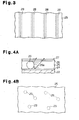
- FIG. 4A A second embodiment of the present invention will now be described with reference to Figs. 4A and 4B. Similar or the same reference numerals are given to those components that are like or the same as the corresponding components of the display 11 shown in Fig. 1.
- a backlight of a display according to the second embodiment has beads 29 instead of the prisms 28.
- the beads 29 function as direction shifting elements.
- the beads 29 are spherical and made of acrylic resin.
- the beads 29 are dispersed in the electroluminescent layer 25.
- the diameter of each bead 29 is the same as the thickness of the electroluminescent layer 25.
- the electroluminescent layer 25 of the second embodiment has a red light emitting layer, a blue light emitting layer, and a green light emitting layer.
- the red light emitting layer is formed of a composition disclosed in Japanese Laid-Open Patent Publication No. 2001-288416, which component is made by dissolving polyoctylfluorene and perylene pigment in xylene and 1,2,4,5-tetramethylbenzene.
- the blue light emitting layer is formed of another composition disclosed in the same publication, which component is made by dissolving polyoctylfluorene in 1,2,3,4-tetramethylbenzene.
- the beads 29 are dispersed in compositions for forming the light emitting layers in advance.
- the electroluminescent layer 25 is formed by consecutively applying the compositions, in which the beads 29 are dispersed, on the first electrode 24.
- the second embodiment provides the following advantages.
- the beads 29 are dispersed in the electroluminescent layer 25. Therefore, the amount of light at any given two portions on the light outputting surface are relatively uniform.
- the beads 29 are spherical. Therefore, the orientation of each bead 29 in the electroluminescent layer 25 need not be taken in to consideration.
- the prisms 28, one of which is shown in Fig. 2, and the beads 29, one of which is shown in Fig. 4A, may be replaced by transparent members 29b containing bubbles 30 shown in Fig 5A.
- the transparent members 29b can be made of acrylic resin or glass.
- the bubbles 30 can be made of nitrogen gas. In this case, light that is emitted in a direction parallel to the second interface S is reflected and refracted not by the interfaces between the electroluminescent layer 25 and the transparent members 29b, but by the interfaces between the transparent members 29b and the bubbles 30.
- the beads 29, one of which is shown in Fig. 4A, may be replaced by truncated cones 29c, one of which is shown in Fig. 5B.
- the beads 29 may be replaced by cone-shaped, pyramid-shaped, truncated pyramid shaped, or hemispherical direction shifting elements. These direction shifting elements are preferably located in the electroluminescent layer 25 such that the bases are closer to the first electrode 24.
- the beads 29, one of which is shown in Fig. 4A, may be replaced by rugby ball shaped direction shifting elements. In this case, the orientation of each shifting element in the electroluminescent layer 25 need not be taken in to consideration.
- the prisms 28, one of which is shown in Fig. 2 may be replaced by prisms 28 shown in Fig. 5C, which are square pole shaped and have trapezoidal cross-section.
- the prisms 28 need not be parallel to each other but may be arranged in a lattice. In this case, the amount of light at any given two portions on the light outputting surface are relatively uniform.
- the prisms 28 may be replaced by a frame located at the peripheral portion of the electroluminescent layer 25. In this case, when applying composition for forming the electroluminescent layer 25, the composition is easily applied to desired portions on the first electrode 24.
- the prisms 28, one of which is shown in Fig. 2, and the beads 29, one of which is shown in Fig. 4A, may be both located in the electroluminescent layer 25.
- the prisms 28 may be located in the peripheral portions of the electroluminescent layer 25 to form a frame, and the beads 29 may be located in regions other than the peripheral portions of the electroluminescent layer 25.
- the substrate 22 may be located closer to the light outputting surface than the electroluminescent layer 25 is.
- the second electrode 26 is made of a light reflecting material such as aluminum
- the first electrode 24 is made of translucent material such as indium tin oxide.
- the prisms 28 are preferably inverted compared to the case of the first embodiment.
- the prisms 28 shown in Fig. 6 may be replaced by other direction shifting elements such as beads 29.
- the prisms 28, one of which is shown in Fig. 2, and the beads 29, one of which is shown in Fig. 4A, may be replaced by direction shifting elements each having a specular surface and reflects light at the specular surface.
- direction shifting elements each having a specular surface and reflects light at the specular surface.
- light that is propagated from the electroluminescent layer 25 to the direction shifting elements is totally reflected by the specular surfaces of the elements.
- the first electrode 24 need not be made of aluminum but may be made of other metal such as chromium.
- the chromium first electrode 24 has higher reflectivity than the first electrode made of aluminum.
- the first electrode 24 may be replaced by a first electrode that has light transmittance type electrode portion and a light reflective film located on the electrode portion.
- the prisms 28, one of which is shown in Fig. 2, and the beads 29, one of which is shown in Fig. 4A, need not contact both of the first electrode 24 and the second electrode 26. That is, the prisms 28 and the beads 29 may be provided in the electroluminescent layer 25 such that the prisms 28 and the beads 29 do not contact one or both of the first and second electrodes 24, 26.
- the beads 29, one of which is shown in Fig. 4A, may be replaced by bubbles.
- the bubbles are formed when applying a composition for forming the electroluminescent layer 25.
- the bubbles are formed by blowing inert gas such as nitrogen or helium into the composition or by adding foaming agent to the composition.
- the refractive index of inert gas such as nitrogen is small and approximately 1.00. Therefore, the critical angle on the interface between the electroluminescent layer 25 and the bubbles is small when light is propagated from the electroluminescent layer 25 to the bubble.
- the electroluminescent layer 25 may be replaced by an electroluminescent layer that emits light other than white light.
- the passivation film 27 need not be formed on a surface of the second electrode 26 that faces the liquid crystal panel 12. Instead, the passivation film 27 may be formed to cover only the peripheral portion of the electroluminescent layer 25.
- the passivation film 27 may be replaced by a metal cover member.
- the substrate 22 may be transparent or opaque.
- the first electrode 24 may function as a cathode, and the second electrode 26 may function as an anode.
- the present invention may be applied to a lighting system other than the backlight panel 13.
- a lighting system other than the backlight panel 13.
- the electroluminescent layer 25, and the second electrode on one side of the substrate 22 another set of the first electrode 24, the electroluminescent layer 25, and the second electrode 26 may be provided on the other side of the substrate 22.
- a surface of the substrate 22 on which the first electrode 24 is provided need not be flat but may be curved.
- the liquid crystal panel 12 may be replaced by a liquid crystal panel including liquid crystal elements, which are driven by an active matrix system.
- the liquid crystal panel 12 may be replaced by a semitransparent liquid crystal panel.
- the present invention may be applied to a display shown in Fig. 7.
- the display of Fig. 7 has organic electroluminescent elements, which are driven by passive matrix system. Each organic electroluminescent element functions as a pixel or a sub-pixel.
- the display of Fig. 7 includes a substrate 31, first electrodes 32, partitions 33, an electroluminescent layer 34, and second electrodes 35.
- the first electrodes 32 are located on the substrate 31 and extend parallel to each other.
- the partitions 33 are located on the substrate 31 and extend perpendicular to the first electrodes 32.
- the electroluminescent layer 34 is provided on portions of the substrate where the partitions 33 are not located.
- the second electrodes 35 are located on the electroluminescent layer 34 and extend perpendicular to the first electrodes 32.
- the partitions 33 can be made of acrylic resin. Each partition 33 insulates an adjacent pair of the second electrodes 35. Two sides 33a of each partition 33 approach each other toward the substrate 31. Portions of the electroluminescent layer 34 that correspond to the intersections between the first electrodes 32 and the second electrodes 35 function as the organic electroluminescent elements.
- a lighting system and a display are capable of efficiently using light emitted by a light emitting element.
- the lighting system and the display according to the present invention include prisms located in an electroluminescent layer, which functions as the light emitting element. Each prism reflects or refracts light incident to the prism such that light emitted by the electroluminescent layer reaches an interface between the electroluminescent layer and a transparent electrode at an angle that is less than the critical angle at the interface.
Landscapes
- Physics & Mathematics (AREA)
- Nonlinear Science (AREA)
- Optics & Photonics (AREA)
- Mathematical Physics (AREA)
- Chemical & Material Sciences (AREA)
- Crystallography & Structural Chemistry (AREA)
- General Physics & Mathematics (AREA)
- Electroluminescent Light Sources (AREA)
- Liquid Crystal (AREA)
Applications Claiming Priority (2)
| Application Number | Priority Date | Filing Date | Title |
|---|---|---|---|
| JP2002197633 | 2002-07-05 | ||
| JP2002197633A JP3861758B2 (ja) | 2002-07-05 | 2002-07-05 | 照明装置及び表示装置 |
Publications (1)
| Publication Number | Publication Date |
|---|---|
| EP1378786A1 true EP1378786A1 (de) | 2004-01-07 |
Family
ID=29720324
Family Applications (1)
| Application Number | Title | Priority Date | Filing Date |
|---|---|---|---|
| EP03015174A Withdrawn EP1378786A1 (de) | 2002-07-05 | 2003-07-03 | Beleuchtungssystem und Anzeigevorrichtung |
Country Status (6)
| Country | Link |
|---|---|
| US (1) | US7433000B2 (de) |
| EP (1) | EP1378786A1 (de) |
| JP (1) | JP3861758B2 (de) |
| KR (1) | KR100574211B1 (de) |
| CN (1) | CN1254713C (de) |
| TW (1) | TWI223573B (de) |
Cited By (1)
| Publication number | Priority date | Publication date | Assignee | Title |
|---|---|---|---|---|
| EP1819203A1 (de) * | 2004-10-28 | 2007-08-15 | Pioneer Corporation | Organische elektrolumineszenzanzeigetafel und verfahren zu ihrer herstellung |
Families Citing this family (19)
| Publication number | Priority date | Publication date | Assignee | Title |
|---|---|---|---|---|
| JP2004355813A (ja) * | 2003-05-27 | 2004-12-16 | Tohoku Pioneer Corp | 自発光表示装置およびこれを用いた情報機器 |
| GB0317909D0 (en) * | 2003-07-31 | 2003-09-03 | Koninkl Philips Electronics Nv | Switchable 2D/3D display |
| JP4192837B2 (ja) * | 2004-04-30 | 2008-12-10 | セイコーエプソン株式会社 | 表示素子及び表示素子の製造方法 |
| CN100456105C (zh) * | 2004-05-17 | 2009-01-28 | 汤姆森许可贸易公司 | 包括oled背光单元的彩色显示设备及其控制方法 |
| US9508957B2 (en) * | 2007-03-30 | 2016-11-29 | The Regents Of The University Of Michigan | OLED with improved light outcoupling |
| JP2009151955A (ja) * | 2007-12-18 | 2009-07-09 | Sony Corp | 面発光光源およびその製造方法 |
| JP5243085B2 (ja) * | 2008-04-03 | 2013-07-24 | ローム株式会社 | 有機エレクトロルミネセンス素子 |
| JP5297072B2 (ja) * | 2008-04-14 | 2013-09-25 | ローム株式会社 | 有機発光装置及び有機発光装置の製造方法 |
| KR100970482B1 (ko) * | 2008-12-04 | 2010-07-16 | 삼성전자주식회사 | 유기 발광소자 및 그 제조방법 |
| KR101084178B1 (ko) * | 2009-12-14 | 2011-11-17 | 한국과학기술원 | 유기 발광 소자, 이를 포함하는 조명 장치, 및 이를 포함하는 유기 발광 디스플레이 장치 |
| WO2013129425A1 (ja) * | 2012-02-27 | 2013-09-06 | 東レ株式会社 | 転写用ドナー基板及びデバイスの製造方法 |
| TWI597877B (zh) | 2013-09-30 | 2017-09-01 | 樂金顯示科技股份有限公司 | 有機電子元件、其製造方法及其應用 |
| KR101928598B1 (ko) | 2013-09-30 | 2018-12-12 | 주식회사 엘지화학 | 폴리이미드 필름 및 그 제조방법 |
| US9691995B2 (en) | 2013-12-04 | 2017-06-27 | Lg Chem, Ltd. | Method of manufacturing substrate for organic electronic device |
| KR20160081388A (ko) | 2014-12-31 | 2016-07-08 | 엘지디스플레이 주식회사 | 유기전자장치 |
| GB201505458D0 (en) | 2015-03-30 | 2015-05-13 | Renishaw Plc | Additive manufacturing apparatus and methods |
| KR102416470B1 (ko) * | 2015-12-21 | 2022-07-04 | 엘지디스플레이 주식회사 | 광효율 향상을 위한 표시패널, 표시장치 및 표시패널을 제조하는 방법 |
| US10686146B2 (en) * | 2017-02-13 | 2020-06-16 | Feng-wen Yen | Paracyclophane-based iridium complexes for organic electroluminescence device |
| TWI831539B (zh) * | 2022-12-26 | 2024-02-01 | 達運精密工業股份有限公司 | 背光模組 |
Citations (8)
| Publication number | Priority date | Publication date | Assignee | Title |
|---|---|---|---|---|
| WO1994021094A1 (en) * | 1993-03-01 | 1994-09-15 | Minnesota Mining And Manufacturing Company | Electroluminescent display with brightness enhancement |
| JPH10189251A (ja) * | 1996-12-27 | 1998-07-21 | Pioneer Electron Corp | ディスプレイ装置 |
| US5798610A (en) * | 1995-04-04 | 1998-08-25 | Koenck; Steven E. | Efficient electroluminescent backlight |
| JP2001004998A (ja) * | 1999-06-24 | 2001-01-12 | Nec Corp | 液晶表示装置 |
| EP1081767A2 (de) * | 1999-09-03 | 2001-03-07 | Sel Semiconductor Energy Laboratory Co., Ltd. | Elektrolumineszente Anzeigevorrichtung und Herstellungsverfahren |
| JP2001350005A (ja) * | 2000-06-09 | 2001-12-21 | Tomoegawa Paper Co Ltd | 光学シートおよびその製造方法 |
| JP2002006776A (ja) * | 2000-06-22 | 2002-01-11 | Nec Corp | 画像表示装置 |
| JP2002198167A (ja) * | 2000-12-25 | 2002-07-12 | Seiko Epson Corp | 照明装置及びその製造方法、表示装置、並びに電子機器 |
Family Cites Families (6)
| Publication number | Priority date | Publication date | Assignee | Title |
|---|---|---|---|---|
| JPH10189237A (ja) | 1996-12-25 | 1998-07-21 | Casio Comput Co Ltd | 面発光体およびそれを使用する液晶表示装置 |
| US6025894A (en) * | 1996-09-04 | 2000-02-15 | Casio Computer Co., Ltd. | Scatter control member for organic electroluminescent light source for passing light with or without scattering depending upon an incident angle |
| JPH1078582A (ja) | 1996-09-04 | 1998-03-24 | Casio Comput Co Ltd | 表示装置及びその駆動方法 |
| JP3785710B2 (ja) | 1996-12-24 | 2006-06-14 | 株式会社デンソー | El表示装置 |
| JP4614400B2 (ja) * | 2000-01-17 | 2011-01-19 | 日東電工株式会社 | 有機el発光装置、偏光面光源装置及び液晶表示装置 |
| JP2001288416A (ja) | 2000-04-07 | 2001-10-16 | Seiko Epson Corp | 塗布液組成物、薄膜形成方法および薄膜 |
-
2002
- 2002-07-05 JP JP2002197633A patent/JP3861758B2/ja not_active Expired - Fee Related
-
2003
- 2003-07-03 EP EP03015174A patent/EP1378786A1/de not_active Withdrawn
- 2003-07-03 US US10/613,417 patent/US7433000B2/en not_active Expired - Fee Related
- 2003-07-04 TW TW092118265A patent/TWI223573B/zh not_active IP Right Cessation
- 2003-07-04 CN CNB031471536A patent/CN1254713C/zh not_active Expired - Fee Related
- 2003-07-04 KR KR1020030045104A patent/KR100574211B1/ko not_active IP Right Cessation
Patent Citations (8)
| Publication number | Priority date | Publication date | Assignee | Title |
|---|---|---|---|---|
| WO1994021094A1 (en) * | 1993-03-01 | 1994-09-15 | Minnesota Mining And Manufacturing Company | Electroluminescent display with brightness enhancement |
| US5798610A (en) * | 1995-04-04 | 1998-08-25 | Koenck; Steven E. | Efficient electroluminescent backlight |
| JPH10189251A (ja) * | 1996-12-27 | 1998-07-21 | Pioneer Electron Corp | ディスプレイ装置 |
| JP2001004998A (ja) * | 1999-06-24 | 2001-01-12 | Nec Corp | 液晶表示装置 |
| EP1081767A2 (de) * | 1999-09-03 | 2001-03-07 | Sel Semiconductor Energy Laboratory Co., Ltd. | Elektrolumineszente Anzeigevorrichtung und Herstellungsverfahren |
| JP2001350005A (ja) * | 2000-06-09 | 2001-12-21 | Tomoegawa Paper Co Ltd | 光学シートおよびその製造方法 |
| JP2002006776A (ja) * | 2000-06-22 | 2002-01-11 | Nec Corp | 画像表示装置 |
| JP2002198167A (ja) * | 2000-12-25 | 2002-07-12 | Seiko Epson Corp | 照明装置及びその製造方法、表示装置、並びに電子機器 |
Non-Patent Citations (5)
| Title |
|---|
| PATENT ABSTRACTS OF JAPAN vol. 1998, no. 12 31 October 1998 (1998-10-31) * |
| PATENT ABSTRACTS OF JAPAN vol. 2000, no. 16 8 May 2001 (2001-05-08) * |
| PATENT ABSTRACTS OF JAPAN vol. 2002, no. 04 4 August 2002 (2002-08-04) * |
| PATENT ABSTRACTS OF JAPAN vol. 2002, no. 05 3 May 2002 (2002-05-03) * |
| PATENT ABSTRACTS OF JAPAN vol. 2002, no. 11 6 November 2002 (2002-11-06) * |
Cited By (2)
| Publication number | Priority date | Publication date | Assignee | Title |
|---|---|---|---|---|
| EP1819203A1 (de) * | 2004-10-28 | 2007-08-15 | Pioneer Corporation | Organische elektrolumineszenzanzeigetafel und verfahren zu ihrer herstellung |
| EP1819203A4 (de) * | 2004-10-28 | 2009-12-23 | Pioneer Corp | Organische elektrolumineszenzanzeigetafel und verfahren zu ihrer herstellung |
Also Published As
| Publication number | Publication date |
|---|---|
| US20040004594A1 (en) | 2004-01-08 |
| TW200403007A (en) | 2004-02-16 |
| CN1254713C (zh) | 2006-05-03 |
| KR20040004168A (ko) | 2004-01-13 |
| TWI223573B (en) | 2004-11-01 |
| CN1472575A (zh) | 2004-02-04 |
| JP3861758B2 (ja) | 2006-12-20 |
| US7433000B2 (en) | 2008-10-07 |
| KR100574211B1 (ko) | 2006-04-27 |
| JP2004039553A (ja) | 2004-02-05 |
Similar Documents
| Publication | Publication Date | Title |
|---|---|---|
| US7433000B2 (en) | Lighting system and display | |
| US7726865B2 (en) | Backlight unit and liquid crystal display device | |
| US11002998B2 (en) | Enhanced privacy switchable backlight system | |
| KR101488998B1 (ko) | 광학 필름, 조명 장치 및 디스플레이 유닛 | |
| US7447417B2 (en) | Backlight assembly and display device having the same | |
| US7940357B2 (en) | Multi view display device and method of fabricating thereof | |
| TWI238899B (en) | Electro-optical device, electronic apparatus, and the method of manufacturing the electro-optical device | |
| JPH095739A (ja) | 導光シ−ト及びその製造方法、及び前記導光シ−トを用いたバックライト及び前記バックライトを用いた液晶表示装置 | |
| US8884858B2 (en) | Liquid crystal display device | |
| WO2007029433A1 (ja) | 透明基板、照明装置、及び液晶表示装置 | |
| US20120113357A1 (en) | Transmissive Liquid Crystal Display with Reflective Mode | |
| WO2011068072A1 (ja) | 光拡散シート、表示パネル、及び表示装置 | |
| US7872709B2 (en) | Liquid crystal display device | |
| WO2009141953A1 (ja) | 液晶表示装置 | |
| CN108107623B (zh) | 显示装置 | |
| CN111965889A (zh) | 背光单元及包括其的显示装置 | |
| US20020000772A1 (en) | Image display apparatus | |
| US20040189588A1 (en) | [back light module and liquid crystal display] | |
| WO2007072600A1 (ja) | 表示装置および液晶表示装置 | |
| US7903200B2 (en) | Liquid crystal display device and mobile electronic device using the same | |
| US20070047111A1 (en) | Prism sheet and backlight unit employed in a liquid crystal display | |
| US20080100778A1 (en) | Liquid crystal display having optical concentrating layer | |
| JP2005300775A (ja) | 液晶表示装置及び面光源 | |
| JP2003270445A (ja) | 導光板、液晶表示装置およびその製造方法 | |
| JP3963080B2 (ja) | 電気光学装置の製造方法および電気光学装置 |
Legal Events
| Date | Code | Title | Description |
|---|---|---|---|
| PUAI | Public reference made under article 153(3) epc to a published international application that has entered the european phase |
Free format text: ORIGINAL CODE: 0009012 |
|
| 17P | Request for examination filed |
Effective date: 20030703 |
|
| AK | Designated contracting states |
Kind code of ref document: A1 Designated state(s): AT BE BG CH CY CZ DE DK EE ES FI FR GB GR HU IE IT LI LU MC NL PT RO SE SI SK TR |
|
| AX | Request for extension of the european patent |
Extension state: AL LT LV MK |
|
| 17Q | First examination report despatched |
Effective date: 20040218 |
|
| AKX | Designation fees paid |
Designated state(s): DE FI GB NL |
|
| STAA | Information on the status of an ep patent application or granted ep patent |
Free format text: STATUS: THE APPLICATION IS DEEMED TO BE WITHDRAWN |
|
| 18D | Application deemed to be withdrawn |
Effective date: 20040629 |