EP1378765A1 - Vorrichtung und Verfahren zum Auslesen von in einer Speicherschicht abgespeicherter Information - Google Patents
Vorrichtung und Verfahren zum Auslesen von in einer Speicherschicht abgespeicherter Information Download PDFInfo
- Publication number
- EP1378765A1 EP1378765A1 EP02014619A EP02014619A EP1378765A1 EP 1378765 A1 EP1378765 A1 EP 1378765A1 EP 02014619 A EP02014619 A EP 02014619A EP 02014619 A EP02014619 A EP 02014619A EP 1378765 A1 EP1378765 A1 EP 1378765A1
- Authority
- EP
- European Patent Office
- Prior art keywords
- storage layer
- storage
- bearing
- receiving device
- air
- Prior art date
- Legal status (The legal status is an assumption and is not a legal conclusion. Google has not performed a legal analysis and makes no representation as to the accuracy of the status listed.)
- Granted
Links
- 238000000034 method Methods 0.000 title claims abstract description 14
- 238000003860 storage Methods 0.000 title claims description 106
- 230000005855 radiation Effects 0.000 claims description 9
- 239000011521 glass Substances 0.000 claims description 4
- 238000005259 measurement Methods 0.000 description 5
- 230000008901 benefit Effects 0.000 description 2
- 230000000694 effects Effects 0.000 description 2
- 230000010355 oscillation Effects 0.000 description 2
- OAICVXFJPJFONN-UHFFFAOYSA-N Phosphorus Chemical compound [P] OAICVXFJPJFONN-UHFFFAOYSA-N 0.000 description 1
- 230000004913 activation Effects 0.000 description 1
- XAGFODPZIPBFFR-UHFFFAOYSA-N aluminium Chemical compound [Al] XAGFODPZIPBFFR-UHFFFAOYSA-N 0.000 description 1
- 229910052782 aluminium Inorganic materials 0.000 description 1
- 230000009286 beneficial effect Effects 0.000 description 1
- 230000005284 excitation Effects 0.000 description 1
- 238000003384 imaging method Methods 0.000 description 1
- 238000004519 manufacturing process Methods 0.000 description 1
- 238000010606 normalization Methods 0.000 description 1
- 229910052698 phosphorus Inorganic materials 0.000 description 1
- 239000011574 phosphorus Substances 0.000 description 1
- 230000036316 preload Effects 0.000 description 1
- 238000005096 rolling process Methods 0.000 description 1
- 239000000523 sample Substances 0.000 description 1
- 238000003892 spreading Methods 0.000 description 1
- 238000011144 upstream manufacturing Methods 0.000 description 1
Images



Classifications
-
- G—PHYSICS
- G03—PHOTOGRAPHY; CINEMATOGRAPHY; ANALOGOUS TECHNIQUES USING WAVES OTHER THAN OPTICAL WAVES; ELECTROGRAPHY; HOLOGRAPHY
- G03B—APPARATUS OR ARRANGEMENTS FOR TAKING PHOTOGRAPHS OR FOR PROJECTING OR VIEWING THEM; APPARATUS OR ARRANGEMENTS EMPLOYING ANALOGOUS TECHNIQUES USING WAVES OTHER THAN OPTICAL WAVES; ACCESSORIES THEREFOR
- G03B42/00—Obtaining records using waves other than optical waves; Visualisation of such records by using optical means
- G03B42/02—Obtaining records using waves other than optical waves; Visualisation of such records by using optical means using X-rays
-
- G—PHYSICS
- G03—PHOTOGRAPHY; CINEMATOGRAPHY; ANALOGOUS TECHNIQUES USING WAVES OTHER THAN OPTICAL WAVES; ELECTROGRAPHY; HOLOGRAPHY
- G03B—APPARATUS OR ARRANGEMENTS FOR TAKING PHOTOGRAPHS OR FOR PROJECTING OR VIEWING THEM; APPARATUS OR ARRANGEMENTS EMPLOYING ANALOGOUS TECHNIQUES USING WAVES OTHER THAN OPTICAL WAVES; ACCESSORIES THEREFOR
- G03B42/00—Obtaining records using waves other than optical waves; Visualisation of such records by using optical means
- G03B42/08—Visualisation of records by optical means
Definitions
- the present invention relates to an apparatus and a method for reading out of information stored in a storage layer according to the generic term of claim 1 or claim 10.
- Such a device and such a method are known from the DE 197 52 925 A1.
- the receiving means is specially placed next to the storage layer attached guide rails.
- This Document shows a device in which the receiving device has a Air bearing that is supported on the storage layer, relative to the storage layer is stored.
- the distance between the receiving device and the storage layer should be kept constant within small tolerances. This is supposed to thanks to an even air pressure between the air bearing and the storage layer be guaranteed.
- air bearings can be considered in view of their small size Air gap, which is on the order of about 2 microns, hardly along the Form the storage layer so that it can be read out optimally To enable information.
- the object of the present invention is a device and to further develop a method of the type mentioned in the introduction such that a storage layer can be read with a good result.
- the invention is based on the knowledge that the above object is achieved if as a guide surface for guiding the receiving device or the storage layer
- a guide surface for guiding the receiving device or the storage layer Such a guide surface is selected when reading out the storage layer will, their level in the direction perpendicular to the plane through the counter is spanned, as precisely as possible with the level of the storage surface for the storage layer coincides in the direction perpendicular to the plane of the storage surface.
- This advantageously applies to the entire course of the guide surface in the feed direction (x direction).
- the course of the receiving device or the Storage layer when reading out the storage layer therefore corresponds to - at least in this direction perpendicular to the plane through the shelf is stretched, considered - exactly the course of the on the shelf overlying storage layer in the direction perpendicular to the plane of the storage surface.
- This can advantageously over the entire course of the Storage layer equal distance between the receiving device and Storage layer, and thus good image sharpness can be guaranteed.
- the storage surface is particularly preferred as the guide surface itself, on which the storage layer is deposited at least during the readout is, in particular - viewed in the feed direction - edge areas of the storage surface, or guide rails along which the receiving device or the Storage layer performed at least during the execution of the relative movement becomes.
- These guide rails are in the direction perpendicular to the plane, which is spanned by the shelf, exactly to the course of the shelf adapted for the storage layer. This results in very good accuracy while leading.
- the two guide surfaces are direct connected to the storage surface, in particular integrally. This can make the match realized in the course in a technically simple way and a special one good agreement can be achieved.
- the solution according to the invention also results in the advantage that the guide surface be optimized with regard to the use of air bearings can.
- the surface of the Storage layers such as phosphorus
- the surface of the Storage layers are only suitable to a limited extent, air bearings to rely on. This is due to the roughness of such a surface With regard to the extreme smoothness required for air bearings.
- the air gap is particularly preferred is between 1 ⁇ m and 4 ⁇ m, with a wedge gap of 2 ⁇ m Mixed friction can result, that is, the bearing could scratch.
- Using a guide surface that does not represent the storage layer can do this extremely be formed smooth, for example made of glass. This can be used for support the receiving device easily use air bearings, which in other Benefits result.
- the bearing is preferably designed as an air bearing, which is arranged such that that an air gap between the bearing and the guide surface during operation of the device is trained.
- Devices according to the invention are, for example used as a digital X-ray scanner, which places very high demands on the constancy of the speed with which the storage layer during of the readout process is read out. With commonly used plain bearings the synchronization becomes due to the friction effect which cannot be completely prevented disturbed. All types of rolling bearings are also non-reactive.
- the bearing device preferably comprises at least two air bearings.
- the least two air bearings form a pair of bearings and are in the z direction, i.e. H. in the direction perpendicular to the spreading of the shelf, on both sides of the shelf arranged. Because two air bearings in the sense of bearings and counter bearings interact, can be achieved that the receiving device is safe is guided along the guide surface almost without friction.
- a particularly precise transport of the receiving device or the storage layer can be realized if the air gap of an air bearing between 1 and 5 ⁇ m, in particular 2 ⁇ m.
- FIG. 1 shows a digital scanner 10 for X-ray applications as an inventive one Device for reading out in a storage layer 12, the stored information is arranged on a storage surface 16.
- the shelf 16 spans an x-y plane. A z direction is perpendicular to this x-y plane.
- the scanner 10 comprises a scanning head 14 in which one Receiving device for receiving one emitted from the storage layer 12 Emission radiation is arranged.
- the receiving device can CCD line with upstream imaging optics included.
- a radiation source for emitting excitation radiation is also in the scanning head 14 arranged, or in a transmitted light scanner below the shelf 16.
- the radiation source can be a plurality of arranged side by side Have laser diodes, the radiation of which via optics onto the storage layer 12 are guided, wherein one line of the storage layer 12 can be excited.
- the scanning head 14 is connected via a first and a second adjustment unit 18a, 18b a first and a second bearing device 20a, 20b connected to which the scanning head 14 is guided on the storage surface 16.
- the two storage devices 20a, 20b are in two edge regions 11a and 11b of the storage surface 16 arranged. This ensures that the course of the edge areas 11a, 11b in the z direction exactly coincides with the course of the storage surface 16.
- the respective level in the z direction of the edge regions 11a, 11b is correct with the level in the z-direction of the storage surface 16.
- Fig. 1 also shows a control means 15 that for controlling the reading of the storage layer 12 by means of the scanner 10 serves.
- the control means 15 is mounted here on the scanning head 14 and contains a memory 17 in which various information required for reading out are stored and accessed by the control means 15 if necessary can.
- the importance of first and second precision buttons 22a, 22b will be discussed in more detail below. But it is possible to use only one instead of two precision buttons.
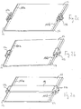
- FIGS. 2a to 2c show a structure of the device according to the invention, in which the storage surface 16 on the two end sides in the y direction is particularly good easy storage and guidance of the scanning head 14 relative to the storage surface 16 has pronounced edge finishes 24. These edge closures 24 serve the guidance of the scanning head 14 in the y direction.
- FIG. 2a shows the scanning head 14 after removing its cover cap. The adjustment units 18a, 18b were also removed and are therefore not shown.
- Figure 2b shows the arrangement of Figure 2a without a scanning head 14, while Figure 2c shows the arrangement of Figure 2b shows, wherein the housing covers of the left and right bearing device 20a, 20b were removed.
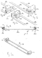
- Figure 3a corresponds to the representation of Figure 2b, but with the storage surface 16 in the illustration has been removed. It can be seen that the left and the right bearing device 20a, 20b with one another via two webs 28a, 28b are connected.
- Figure 3b shows the right storage device 20b and Figure 3c the left bearing device 20a of Figure 3a in more detail. The rear view of the left storage device 20a is shown in Figure 3d.
- Figure 4 shows schematically a partially sectioned front view of the illustration of Figure 3a, from which it can be seen that the bearing devices 20a and 20b via two air bearings 30a, 30b or interacting in the z-axis direction 30c, 30d.
- Via a connection 32a of the right bearing device 20b are their air bearings 30a, 30b and via a connection 32b of the left bearing device 20a, their air bearings 30c, 30d are resilient against one another in the z-axis direction biased.
- Forces to generate the prestresses can, for example can be realized by means of disc springs, which on the connections 32a and 32b act.
- the air pressure generated during operation by the air bearings forms counter forces to the forces generated by the disc springs.
- FIG. 5a shows the air bearings 30c, 30d and 34b of the left bearing device 20a, Figure 5b, the air bearings 30a1, 30a2, 30b and 34a of the right bearing device 20b with greater accuracy.
- One of the air bearings used is representative shown in Figures 6a to c and, without specifying its location in one of the bearing devices 20a, 20b, generally designated by the reference number 36.
- the air bearing 36 comprises an air connection 38 and a bearing 40, in the example of a tapered screw to achieve a point bearing 42 is arranged, which with the associated housing cover respective storage device 20a, 20b and thus the scanning head 14 to be stored is rigidly connected.
- a thread is in the head of the taper screw 42 brought in. Due to the punctiform bearing over the tip of the taper screw 42 a self-aligning bearing is realized.
- FIG. 6 b shows a top view of the air bearing 36 Anti-rotation device 44 arranged to prevent the air bearing 36 in the rotated in Figure 6b with an arrow 47 direction.
- the air outlet side of the air bearing 36 is identified by the reference symbol 48. she contains air outlets through which the air port 38 enters the bearing imported air is blown out.
- the upper air bearing 30a (see Figure 4) here comprises two air bearings 30a1, 30a2 in the x direction are arranged side by side. This ensures that the readhead 14 does not tip over the y-axis during activation of the air bearings.
- the anti-rotation lock 44 generally described above corresponds here to anti-rotation locks 46 for the air bearing 30a2, anti-rotation devices 49 for the air bearing 30a1 and anti-rotation devices 50 for the air bearing 34a.
- the anti-twist devices 46, 49, 50 are at their respective ends shown in FIG. 5b attached to the housing cover, not shown, of the bearing device 20b.
- the tapered screws 42 of FIGS. 5a, 5b are connected via the connections 32a, 32b, with which the bearing and counter bearing are connected to one another, with the scanning head 14 connected.
- the 5b also shows a plate spring 51b, which is used to generate a Force to realize a preload of the air bearing pair 30a1, 30a2 and 30b serves in the z direction.
- the plate spring 51b is threaded on its upper side provided, via which the plate spring 51b on the housing cover of the Bearing device 20b can be attached (see also illustration in Fig. 3b).
- the force generated by the plate spring 51b is here via a connecting plate 55b transferred to the air bearing 30b, which is connected to the connecting plate 55b is.
- the connection plate 55b is in the x-direction Rotation axis 53b connected, the tilting of the connecting plate 55b and thus enables the air bearing 30b along a direction of rotation D.
- the axis of rotation 53b is at both ends in the housing (not shown) Bearing device 20b attached.
- the air bearings 30a1, 30a2 and 30b in Air pressures generated during operation form a counterforce to that generated by the disc spring 51b generated force. This creates the pincer-shaped storage of the shelf 16, which is located between the bearings 30a1, 30a2 and 30b.
- a the plate spring 51b corresponding further plate spring (not shown), one Connection plate 55a and an axis of rotation 53a are for the bearing device 20a provided to also because the pincer-shaped storage of the storage surface 16 to ensure.
- FIGS. 7a and 7b show an embodiment of a precision button 22 already shown in FIG.
- the scanning head 14, which is connected to the precision probe 22 is lowered as far as in the z 1 direction, ie in the direction of the storage layer 12, until an upper side 52 of a contact pin 58 comes into contact with a contact spring 54.
- an underside 60 of the contact pin 58 is in contact with the storage layer 12.
- a spring 56 ensures that without corresponding pressure on the underside 60 of the contact pin 58, ie without resistance from the storage layer 12, the upper side 52 of the contact pin 58 and the contact spring 54 are not in contact.
- an optimal distance between the storage layer 12 and the receiving device of the scanning head 14 is set by means of the adjusting unit 18 shown in FIG 1 direction is reversed. This results in a distance between the underside 60 of the contact pin 58 and the storage layer 12.
- the setting of the optimal distance is controlled for the sake of simplicity by the control means 15 (FIG. 1).
- the optimal distance can be determined by calibrating the scanner beforehand. The optimal distance ensures in particular that the image sharpness when reading out the storage layer 12 is very good and, if possible, is the same over the entire area of the storage layer 12.
- the adjustment unit 18 comprises two rods guided in parallel 62a, 62b, on the one hand, via bearings 64a, 64b with one of the bearing devices 20a, 20b, on the other hand coupled to the scanning head 14 via bearings 66a, 66b are.
- the rod can be operated by a stepper motor 68 with an integrated spindle 69 62a are deflected, this movement being a corresponding deflection is transmitted to the rod 62b.
- This allows the distance between Storage layer 12 and receiving device, i. H. Readhead 14, high precision to adjust.
- Springs 70a, 70b ensure that the bracing is as free of play as possible Adjustment unit 18.
- Such a distance setting can be used for different storage layers in each case before the start of a reading process, during the reading process the distance is advantageously maintained. This improves the Readout quality, as different storage layers in particular due to production have different thicknesses, so that with different storage layers 12 different distances between the surface of each Storage layer 12 and the receiving device contained in the scanning head 14 would be present.
- the distance can advantageously be during a readout process be readjusted. For the sake of simplicity, this is done using the Tax means 15. In particular for the implementation of the latter variant it is beneficial if the distance is continuous during a scan is determined.
- Mechanical scanning is suitable for this, for example by a measuring wheel, which has minimal contact force on the surface of the storage layer 12 runs along during the scanning process and the level of the storage layer transferred to a measuring system.
- a non-contact Distance measurement can be used, but be careful is that this does not stimulate the storage layer to emit radiation becomes.
- Storage layer 12 the result of the previously performed normalization, respectively the distance measurement, stored in a memory 17 (see FIG. 1) and is assigned to the storage layer.
- the cassette becomes Reading out the storage layer 12 contained therein in the inventive ones Scanner inserted and the storage layer 12 then out of the cassette pulled out and pulled into the scanner.
- standardization can be carried out using a transponder according to the invention Device for reading out the information from the storage layer be transmitted.
- the assigned storage layer can the stored distance of Read head 14 to the tray 16 can be accessed and adjusted.
- Figure 9 shows that the use of air bearings causes the scanning head to oscillate 14 around the z-axis is possible without causing a slip-stick effect comes.
- the device according to the invention is also special suitable for driving the receiving device 26 on both sides.
- the device according to the invention can be used both in variants in which the storage layer 12 and the storage surface 16 are firmly mounted in the device are. It can also be used in a variant in which the storage layer 16, optionally applied to an additional carrier layer, for example made of aluminum, only for reading the storage layer 12 into the device is introduced.
Landscapes
- Physics & Mathematics (AREA)
- General Physics & Mathematics (AREA)
- Measurement Of Radiation (AREA)
- Facsimile Scanning Arrangements (AREA)
- Radiography Using Non-Light Waves (AREA)
- Optical Recording Or Reproduction (AREA)
- Semiconductor Memories (AREA)
Abstract
Description
- Fig. 1
- in schematischer perspektivischer Darstellung eine erste Ausführungsform einer erfindungsgemäßen Vorrichtung zum Auslesen von in einer Speicherschicht abgespeicherter Information;
- Fig. 2a - 2c
- eine zweite Ausführungsform einer erfindungsgemäßen Vorrichtung nach sukzessivem Abbau von Teilen der erfindungsgemäßen Vorrichtung;
- Fig. 3a - 3d
- eine mit der Darstellung von Figur 2b korrespondierende Darstellung der Lagerung der Empfangsvorrichtung, wobei aus den Darstellungen der Figur 3b - 3d Details deutlich zu erkennen sind;
- Fig. 4
- die Darstellung von Figur 3a in teilweise geschnittener Darstellung in Frontansicht;
- Fig. 5a, b
- eine detailliertere Darstellung von Einzelheiten der Figur 3b;
- Fig. 6
- eine detaillierte Darstellung eines bevorzugt verwendeten Luftlagers;
- Fig. 7a, b
- in Seitenansicht und perspektivischer Darstellung einen bevorzugt bei der erfindungsgemäßen Vorrichtung zu verwendenden Präzisionstaster;
- Fig. 8
- in detaillierter Darstellung eine bevorzugt verwendbare Verstelleinheit; und
- Fig. 9
- in schematischer Darstellung das durch die Verwendung von Luftlagern ermöglichte Pendeln der Empfangsvorrichtung, beispielhaft gezeigt am Pendeln um die z-Achse.
Claims (10)
- Vorrichtung zum Auslesen von in einer Speicherschicht (12) abgespeicherter Information mitdadurch gekennzeichnet, dasseiner Empfangsvorrichtung (14) zum Empfangen einer von der Speicherschicht (12) ausgesandten Emissionsstrahlung;einer Ablagefläche (16) zum Ablegen der Speicherschicht (12), wobei durch die Ablagefläche (16) eine x-y-Ebene definiert ist; undeinem Führungsmittel (20a, 20b) zum Führen der Empfangsvorrichtung (14) oder der Speicherschicht (12) auf einer Führungsfläche (11a, 11b, 16) während des Erzeugens einer Relativbewegung zwischen der Empfangsvorrichtung (14) und der Speicherschicht (12) in x-Richtung, wobei die Führungsfläche (11a, 11b, 16) von der Speicherschicht (12) unabhängig ist;
das Niveau der Führungsfläche (11a, 11b, 16) in eine z-Richtung, die senkrecht zur x-y-Ebene verläuft, mit dem Niveau der Ablagefläche (16) in z-Richtung übereinstimmt. - Vorrichtung nach Anspruch 1,
dadurch gekennzeichnet, dass die Führungsfläche (11a, 11b, 16) zwei Teilführungsflächen (11a, 11b) aufweist, die in y-Richtung beidseitig der Ablagefläche (16) angeordnet sind. - Vorrichtung nach Anspruch 2,
dadurch gekennzeichnet, dass die Teilführungsflächen (11a, 11b) mit der Ablagefläche (16) verbunden sind. - Vorrichtung nach Anspruch 3,
dadurch gekennzeichnet, dass die Teilführungsflächen (11a, 11b) mit der Ablagefläche (16) integral verbunden sind. - Vorrichtung nach einem der vorhergehenden Ansprüche,
dadurch gekennzeichnet, dass die Führungsfläche (11a, 11b, 16) eine Glasoberfläche aufweist. - Vorrichtung nach einem der vorhergehenden Ansprüche,
dadurch gekennzeichnet, dass das Führungsmittel (20a, 20b) ein Lager (20) zum Lagern der Empfangsvorrichtung (14) aufweist. - Vorrichtung nach Anspruch 6,
dadurch gekennzeichnet, dass das Lager (20) als Luftlager (36) ausgebildet ist. - Vorrichtung nach Anspruch 7,
dadurch gekennzeichnet, dass das Lager (20) mindestens zwei Luftlager (36) umfaßt, die ein Lagerpaar bilden und in eine z-Richtung, die senkrecht zu der durch die Ablagefläche definierten xy-Ebene verläuft, beidseits der Führungsfläche (11a, 11b, 16) angeordnet sind. - Vorrichtung nach Anspruch 8,
dadurch gekennzeichnet, dass die Luftlager (36) des Lagerpaares zangenförmig miteinander verbunden und gegeneinander vorgespannt sind. - Verfahren zum Auslesen von in einer Speicherschicht (12) abgespeicherter Information unter Verwendung einer Empfangsvorrichtung (14) zum Empfangen von Emissionsstrahlung, die von der Speicherschicht (12) ausgegeben wurde, wobei sich die Speicherschicht (12) auf einer Ablagefläche (16) befindet, durch die eine x-y-Ebene definiert wird, folgende Schritte umfassend:dadurch gekennzeichnet, dassa) Empfangen einer von der Speicherschicht (12) ausgesandten Emissionsstrahlung;b) Erzeugen einer Relativbewegung zwischen der Empfangsvorrichtung (14) und der Speicherschicht (12) in x-Richtung; undc) Führen der Empfangsvorrichtung (14) oder der Speicherschicht (12) während des Erzeugens der Relativbewegung mittels eines Führungsmittels (20a, 20b) auf einer Führungsfläche (11a, 11b, 16), die von der Speicherschicht (12) unabhängig ist;
beim Führen der Empfangsvorrichtung (14) das Niveau der Führungsfläche (11a, 11b, 16) in eine z-Richtung, die senkrecht zur x-y-Ebene verläuft, mit dem Niveau der Ablagefläche (16) in z-Richtung übereinstimmt.
Priority Applications (5)
| Application Number | Priority Date | Filing Date | Title |
|---|---|---|---|
| AT02014619T ATE459017T1 (de) | 2002-07-02 | 2002-07-02 | Vorrichtung und verfahren zum auslesen von in einer speicherschicht abgespeicherter information |
| EP02014619A EP1378765B1 (de) | 2002-07-02 | 2002-07-02 | Vorrichtung und Verfahren zum Auslesen von in einer Speicherschicht abgespeicherter Information |
| DE50214232T DE50214232D1 (de) | 2002-07-02 | 2002-07-02 | Vorrichtung und Verfahren zum Auslesen von in einer Speicherschicht abgespeicherter Information |
| US10/610,273 US7342243B2 (en) | 2002-07-02 | 2003-06-30 | Device and method for reading out information stored in a storage layer |
| JP2003270107A JP4041029B2 (ja) | 2002-07-02 | 2003-07-01 | 記憶層に記憶された情報を読み出す装置と方法 |
Applications Claiming Priority (1)
| Application Number | Priority Date | Filing Date | Title |
|---|---|---|---|
| EP02014619A EP1378765B1 (de) | 2002-07-02 | 2002-07-02 | Vorrichtung und Verfahren zum Auslesen von in einer Speicherschicht abgespeicherter Information |
Publications (2)
| Publication Number | Publication Date |
|---|---|
| EP1378765A1 true EP1378765A1 (de) | 2004-01-07 |
| EP1378765B1 EP1378765B1 (de) | 2010-02-24 |
Family
ID=29719696
Family Applications (1)
| Application Number | Title | Priority Date | Filing Date |
|---|---|---|---|
| EP02014619A Expired - Lifetime EP1378765B1 (de) | 2002-07-02 | 2002-07-02 | Vorrichtung und Verfahren zum Auslesen von in einer Speicherschicht abgespeicherter Information |
Country Status (5)
| Country | Link |
|---|---|
| US (1) | US7342243B2 (de) |
| EP (1) | EP1378765B1 (de) |
| JP (1) | JP4041029B2 (de) |
| AT (1) | ATE459017T1 (de) |
| DE (1) | DE50214232D1 (de) |
Cited By (2)
| Publication number | Priority date | Publication date | Assignee | Title |
|---|---|---|---|---|
| US7342243B2 (en) | 2002-07-02 | 2008-03-11 | Agfa-Gevaert Healthcare Gmbh | Device and method for reading out information stored in a storage layer |
| EP2383973A1 (de) * | 2005-09-27 | 2011-11-02 | Dürr Dental AG | Vorrichtung zum Auslesen von insbesondere flexiblen Speicherfolien |
Families Citing this family (2)
| Publication number | Priority date | Publication date | Assignee | Title |
|---|---|---|---|---|
| DE502004007905D1 (de) * | 2004-09-22 | 2008-10-02 | Agfa Gevaert Healthcare Gmbh | Vorrichtung und Verfahren zum Auslesen von in einer Speicherleuchtstoffplatte gespeicherten Röntgeninformationen |
| ATE439005T1 (de) * | 2005-12-29 | 2009-08-15 | Agfa Gevaert Healthcare Gmbh | Antriebsvorrichtung für eine optische abtasteinrichtung |
Citations (3)
| Publication number | Priority date | Publication date | Assignee | Title |
|---|---|---|---|---|
| EP0287117A1 (de) * | 1987-04-17 | 1988-10-19 | Fuji Photo Film Co., Ltd. | Strahlungsbildaufzeichnungs- und Wiedergabesystem |
| DE19752925A1 (de) * | 1997-11-28 | 1999-06-24 | Agfa Gevaert Ag | Vorrichtung zum Auslesen von einer in einem Phosphorträger abgespeicherten Information und Röntgenkassette |
| EP1081507A2 (de) * | 1999-08-07 | 2001-03-07 | Agfa-Gevaert AG | Vorrichtung zum Auslesen von in einer Speicherschicht abgespeicherten Informationen durch Anregungsstrahlung und Emfangsmittel |
Family Cites Families (12)
| Publication number | Priority date | Publication date | Assignee | Title |
|---|---|---|---|---|
| JPH1198314A (ja) | 1997-09-17 | 1999-04-09 | Konica Corp | 画像読み取り装置 |
| JPH11334947A (ja) | 1998-05-29 | 1999-12-07 | Fuji Photo Film Co Ltd | シート搬送装置 |
| JP4209983B2 (ja) | 1999-01-21 | 2009-01-14 | 住友重機械工業株式会社 | ステージ機構 |
| DE19922345B4 (de) | 1999-05-14 | 2005-07-28 | Siemens Ag | Vorrichtung zur Auslesung einer Speicherleuchtstoffplatte |
| DE19946743C1 (de) | 1999-09-29 | 2000-11-23 | Siemens Ag | Röntgendiagnostikeinrichtung mit einem Speicherleuchtschirm |
| DE19962773A1 (de) * | 1999-12-23 | 2001-07-26 | Agfa Gevaert Ag | Vorrichtung zum Auslesen von in einer Speicherschicht abgespeicherten Informationen sowie Röntgenkassette und Röntgentisch |
| JP2001245100A (ja) * | 2000-02-25 | 2001-09-07 | Fuji Photo Film Co Ltd | 蓄積性蛍光体を用いた画像情報読取方法および装置並びに固体画像検出器 |
| JP4470128B2 (ja) | 2000-03-07 | 2010-06-02 | 日本精工株式会社 | アクチュエータ |
| JP2001350228A (ja) * | 2000-06-07 | 2001-12-21 | Fuji Photo Film Co Ltd | 放射線画像読取装置 |
| US6784448B2 (en) * | 2001-02-27 | 2004-08-31 | Fuji Photo Film Co., Ltd. | Method for reading radiation image from stimulable phosphor sheet |
| US6861662B2 (en) * | 2002-01-17 | 2005-03-01 | Fuji Photo Film Co., Ltd. | Image information reading apparatus |
| EP1378765B1 (de) | 2002-07-02 | 2010-02-24 | Agfa-Gevaert HealthCare GmbH | Vorrichtung und Verfahren zum Auslesen von in einer Speicherschicht abgespeicherter Information |
-
2002
- 2002-07-02 EP EP02014619A patent/EP1378765B1/de not_active Expired - Lifetime
- 2002-07-02 DE DE50214232T patent/DE50214232D1/de not_active Expired - Lifetime
- 2002-07-02 AT AT02014619T patent/ATE459017T1/de not_active IP Right Cessation
-
2003
- 2003-06-30 US US10/610,273 patent/US7342243B2/en not_active Expired - Fee Related
- 2003-07-01 JP JP2003270107A patent/JP4041029B2/ja not_active Expired - Fee Related
Patent Citations (3)
| Publication number | Priority date | Publication date | Assignee | Title |
|---|---|---|---|---|
| EP0287117A1 (de) * | 1987-04-17 | 1988-10-19 | Fuji Photo Film Co., Ltd. | Strahlungsbildaufzeichnungs- und Wiedergabesystem |
| DE19752925A1 (de) * | 1997-11-28 | 1999-06-24 | Agfa Gevaert Ag | Vorrichtung zum Auslesen von einer in einem Phosphorträger abgespeicherten Information und Röntgenkassette |
| EP1081507A2 (de) * | 1999-08-07 | 2001-03-07 | Agfa-Gevaert AG | Vorrichtung zum Auslesen von in einer Speicherschicht abgespeicherten Informationen durch Anregungsstrahlung und Emfangsmittel |
Cited By (3)
| Publication number | Priority date | Publication date | Assignee | Title |
|---|---|---|---|---|
| US7342243B2 (en) | 2002-07-02 | 2008-03-11 | Agfa-Gevaert Healthcare Gmbh | Device and method for reading out information stored in a storage layer |
| EP2383973A1 (de) * | 2005-09-27 | 2011-11-02 | Dürr Dental AG | Vorrichtung zum Auslesen von insbesondere flexiblen Speicherfolien |
| EP2431807A1 (de) * | 2005-09-27 | 2012-03-21 | Dürr Dental AG | Vorrichtung zum Auslesen von insbesondere flexiblen Speicherfolien |
Also Published As
| Publication number | Publication date |
|---|---|
| JP4041029B2 (ja) | 2008-01-30 |
| ATE459017T1 (de) | 2010-03-15 |
| US7342243B2 (en) | 2008-03-11 |
| JP2004086200A (ja) | 2004-03-18 |
| US20040004198A1 (en) | 2004-01-08 |
| EP1378765B1 (de) | 2010-02-24 |
| DE50214232D1 (de) | 2010-04-08 |
Similar Documents
| Publication | Publication Date | Title |
|---|---|---|
| DE69320762T2 (de) | Mit hoher Genauigkeit bewegliche Plattform | |
| DE3851065T2 (de) | Vorrichtung zum montieren einer druckplatte auf einem zylinder. | |
| DE4235549C2 (de) | Gerät zum Justieren einer Lichtquelleneinheit | |
| DE3920888C2 (de) | Verfahren zur Prüfung der Enden von gestapelten Zigaretten | |
| DE3133374C2 (de) | Druckkopfwagen mit Zugmitteln in einer Druckvorrichtung | |
| WO2000030802A1 (de) | Vorrichtung und verfahren zum abtasten einer objektfläche mit einem laserstrahl | |
| DE2725959C3 (de) | Elektronenstrahl-Bearbeitungseinrichtung | |
| EP0867732A2 (de) | Lichtgitter und Verfahren zu seiner Herstellung | |
| DE19709561C2 (de) | Anlage zur Bearbeitung von Chip- und/oder Magnetstreifenkarten | |
| EP0863482A2 (de) | Anlage zur Bearbeitung von Chip- und/oder Magnetstreifenkarten | |
| DE102013214741A1 (de) | Laserbearbeitungsvorrichtung | |
| DE102018107868B4 (de) | Drahtbasiertes additives Fertigungssystem | |
| DE4323009A1 (de) | Vorrichtung zum Ausbilden eines Federwindungsabstands | |
| EP1378766B1 (de) | Vorrichtung und Verfahren zum Auslesen von in einer Speicherschicht abgespeicherter Information | |
| DE3703217A1 (de) | Optische abtasteinrichtung | |
| DE19821763B4 (de) | Vorschubeinrichtung für eine Industriemaschine und Industriemaschine, die diese verwendet | |
| EP1378767B1 (de) | Vorrichtung und Verfahren zum Auslesen von in einer Speicherschicht abgespeicherter Information | |
| DE4313796A1 (de) | Laserbearbeitungsvorrichtung | |
| DE102019204032B4 (de) | Vorrichtung zur Erzeugung einer räumlich modulierbaren Leistungsdichteverteilung aus Laserstrahlung | |
| EP1378765B1 (de) | Vorrichtung und Verfahren zum Auslesen von in einer Speicherschicht abgespeicherter Information | |
| DE60209367T2 (de) | Vorrichtung zur messung oder maschinellen bearbeitung eines objekts mit einer verschiebungsstufe mit keilförmigen führungen | |
| DE3801708A1 (de) | Punktreihenmatrix-drucker | |
| DE102017211254B4 (de) | Vorrichtung und Verfahren zur Herstellung eines Dokumentenkörpers | |
| DE102022120336A1 (de) | Lasergestützte Lötvorrichtung und Lotaufbringungsmaschine | |
| EP1081507B1 (de) | Vorrichtung zum Auslesen von in einer Speicherschicht abgespeicherten Informationen durch Anregungsstrahlung und Empfangsmittel |
Legal Events
| Date | Code | Title | Description |
|---|---|---|---|
| PUAI | Public reference made under article 153(3) epc to a published international application that has entered the european phase |
Free format text: ORIGINAL CODE: 0009012 |
|
| AK | Designated contracting states |
Kind code of ref document: A1 Designated state(s): AT BE BG CH CY CZ DE DK EE ES FI FR GB GR IE IT LI LU MC NL PT SE SK TR |
|
| AX | Request for extension of the european patent |
Extension state: AL LT LV MK RO SI |
|
| 17P | Request for examination filed |
Effective date: 20040707 |
|
| AKX | Designation fees paid |
Designated state(s): AT BE BG CH CY CZ DE DK EE ES FI FR GB GR IE IT LI LU MC NL PT SE SK TR |
|
| RAP1 | Party data changed (applicant data changed or rights of an application transferred) |
Owner name: AGFA-GEVAERT HEALTHCARE GMBH |
|
| 17Q | First examination report despatched |
Effective date: 20061229 |
|
| RAP1 | Party data changed (applicant data changed or rights of an application transferred) |
Owner name: AGFA-GEVAERT HEALTHCARE GMBH |
|
| GRAP | Despatch of communication of intention to grant a patent |
Free format text: ORIGINAL CODE: EPIDOSNIGR1 |
|
| GRAS | Grant fee paid |
Free format text: ORIGINAL CODE: EPIDOSNIGR3 |
|
| GRAA | (expected) grant |
Free format text: ORIGINAL CODE: 0009210 |
|
| AK | Designated contracting states |
Kind code of ref document: B1 Designated state(s): AT BE BG CH CY CZ DE DK EE ES FI FR GB GR IE IT LI LU MC NL PT SE SK TR |
|
| REG | Reference to a national code |
Ref country code: GB Ref legal event code: FG4D Free format text: NOT ENGLISH |
|
| REG | Reference to a national code |
Ref country code: CH Ref legal event code: EP |
|
| REG | Reference to a national code |
Ref country code: IE Ref legal event code: FG4D Free format text: LANGUAGE OF EP DOCUMENT: GERMAN |
|
| REF | Corresponds to: |
Ref document number: 50214232 Country of ref document: DE Date of ref document: 20100408 Kind code of ref document: P |
|
| REG | Reference to a national code |
Ref country code: NL Ref legal event code: VDEP Effective date: 20100224 |
|
| PG25 | Lapsed in a contracting state [announced via postgrant information from national office to epo] |
Ref country code: PT Free format text: LAPSE BECAUSE OF FAILURE TO SUBMIT A TRANSLATION OF THE DESCRIPTION OR TO PAY THE FEE WITHIN THE PRESCRIBED TIME-LIMIT Effective date: 20100625 |
|
| PG25 | Lapsed in a contracting state [announced via postgrant information from national office to epo] |
Ref country code: FI Free format text: LAPSE BECAUSE OF FAILURE TO SUBMIT A TRANSLATION OF THE DESCRIPTION OR TO PAY THE FEE WITHIN THE PRESCRIBED TIME-LIMIT Effective date: 20100224 |
|
| REG | Reference to a national code |
Ref country code: IE Ref legal event code: FD4D |
|
| PG25 | Lapsed in a contracting state [announced via postgrant information from national office to epo] |
Ref country code: SE Free format text: LAPSE BECAUSE OF FAILURE TO SUBMIT A TRANSLATION OF THE DESCRIPTION OR TO PAY THE FEE WITHIN THE PRESCRIBED TIME-LIMIT Effective date: 20100224 Ref country code: CY Free format text: LAPSE BECAUSE OF FAILURE TO SUBMIT A TRANSLATION OF THE DESCRIPTION OR TO PAY THE FEE WITHIN THE PRESCRIBED TIME-LIMIT Effective date: 20100224 Ref country code: EE Free format text: LAPSE BECAUSE OF FAILURE TO SUBMIT A TRANSLATION OF THE DESCRIPTION OR TO PAY THE FEE WITHIN THE PRESCRIBED TIME-LIMIT Effective date: 20100224 Ref country code: ES Free format text: LAPSE BECAUSE OF FAILURE TO SUBMIT A TRANSLATION OF THE DESCRIPTION OR TO PAY THE FEE WITHIN THE PRESCRIBED TIME-LIMIT Effective date: 20100604 Ref country code: GR Free format text: LAPSE BECAUSE OF FAILURE TO SUBMIT A TRANSLATION OF THE DESCRIPTION OR TO PAY THE FEE WITHIN THE PRESCRIBED TIME-LIMIT Effective date: 20100525 Ref country code: IE Free format text: LAPSE BECAUSE OF FAILURE TO SUBMIT A TRANSLATION OF THE DESCRIPTION OR TO PAY THE FEE WITHIN THE PRESCRIBED TIME-LIMIT Effective date: 20100224 Ref country code: NL Free format text: LAPSE BECAUSE OF FAILURE TO SUBMIT A TRANSLATION OF THE DESCRIPTION OR TO PAY THE FEE WITHIN THE PRESCRIBED TIME-LIMIT Effective date: 20100224 |
|
| PG25 | Lapsed in a contracting state [announced via postgrant information from national office to epo] |
Ref country code: SK Free format text: LAPSE BECAUSE OF FAILURE TO SUBMIT A TRANSLATION OF THE DESCRIPTION OR TO PAY THE FEE WITHIN THE PRESCRIBED TIME-LIMIT Effective date: 20100224 Ref country code: BG Free format text: LAPSE BECAUSE OF FAILURE TO SUBMIT A TRANSLATION OF THE DESCRIPTION OR TO PAY THE FEE WITHIN THE PRESCRIBED TIME-LIMIT Effective date: 20100524 Ref country code: CZ Free format text: LAPSE BECAUSE OF FAILURE TO SUBMIT A TRANSLATION OF THE DESCRIPTION OR TO PAY THE FEE WITHIN THE PRESCRIBED TIME-LIMIT Effective date: 20100224 |
|
| PLBE | No opposition filed within time limit |
Free format text: ORIGINAL CODE: 0009261 |
|
| STAA | Information on the status of an ep patent application or granted ep patent |
Free format text: STATUS: NO OPPOSITION FILED WITHIN TIME LIMIT |
|
| BERE | Be: lapsed |
Owner name: AGFA-GEVAERT HEALTHCARE G.M.B.H. Effective date: 20100731 |
|
| PG25 | Lapsed in a contracting state [announced via postgrant information from national office to epo] |
Ref country code: DK Free format text: LAPSE BECAUSE OF FAILURE TO SUBMIT A TRANSLATION OF THE DESCRIPTION OR TO PAY THE FEE WITHIN THE PRESCRIBED TIME-LIMIT Effective date: 20100224 |
|
| 26N | No opposition filed |
Effective date: 20101125 |
|
| PG25 | Lapsed in a contracting state [announced via postgrant information from national office to epo] |
Ref country code: MC Free format text: LAPSE BECAUSE OF NON-PAYMENT OF DUE FEES Effective date: 20100731 |
|
| REG | Reference to a national code |
Ref country code: CH Ref legal event code: PL |
|
| PG25 | Lapsed in a contracting state [announced via postgrant information from national office to epo] |
Ref country code: IT Free format text: LAPSE BECAUSE OF FAILURE TO SUBMIT A TRANSLATION OF THE DESCRIPTION OR TO PAY THE FEE WITHIN THE PRESCRIBED TIME-LIMIT Effective date: 20100224 |
|
| PG25 | Lapsed in a contracting state [announced via postgrant information from national office to epo] |
Ref country code: CH Free format text: LAPSE BECAUSE OF NON-PAYMENT OF DUE FEES Effective date: 20100731 Ref country code: LI Free format text: LAPSE BECAUSE OF NON-PAYMENT OF DUE FEES Effective date: 20100731 |
|
| PG25 | Lapsed in a contracting state [announced via postgrant information from national office to epo] |
Ref country code: BE Free format text: LAPSE BECAUSE OF NON-PAYMENT OF DUE FEES Effective date: 20100731 |
|
| PG25 | Lapsed in a contracting state [announced via postgrant information from national office to epo] |
Ref country code: AT Free format text: LAPSE BECAUSE OF NON-PAYMENT OF DUE FEES Effective date: 20100702 |
|
| PGFP | Annual fee paid to national office [announced via postgrant information from national office to epo] |
Ref country code: FR Payment date: 20120628 Year of fee payment: 11 |
|
| PG25 | Lapsed in a contracting state [announced via postgrant information from national office to epo] |
Ref country code: LU Free format text: LAPSE BECAUSE OF NON-PAYMENT OF DUE FEES Effective date: 20100702 |
|
| PG25 | Lapsed in a contracting state [announced via postgrant information from national office to epo] |
Ref country code: TR Free format text: LAPSE BECAUSE OF FAILURE TO SUBMIT A TRANSLATION OF THE DESCRIPTION OR TO PAY THE FEE WITHIN THE PRESCRIBED TIME-LIMIT Effective date: 20100224 |
|
| PGFP | Annual fee paid to national office [announced via postgrant information from national office to epo] |
Ref country code: GB Payment date: 20120703 Year of fee payment: 11 |
|
| REG | Reference to a national code |
Ref country code: DE Ref legal event code: R084 Ref document number: 50214232 Country of ref document: DE Effective date: 20130212 |
|
| GBPC | Gb: european patent ceased through non-payment of renewal fee |
Effective date: 20130702 |
|
| REG | Reference to a national code |
Ref country code: FR Ref legal event code: ST Effective date: 20140331 |
|
| PG25 | Lapsed in a contracting state [announced via postgrant information from national office to epo] |
Ref country code: GB Free format text: LAPSE BECAUSE OF NON-PAYMENT OF DUE FEES Effective date: 20130702 |
|
| PG25 | Lapsed in a contracting state [announced via postgrant information from national office to epo] |
Ref country code: FR Free format text: LAPSE BECAUSE OF NON-PAYMENT OF DUE FEES Effective date: 20130731 |
|
| PGFP | Annual fee paid to national office [announced via postgrant information from national office to epo] |
Ref country code: DE Payment date: 20140618 Year of fee payment: 13 |
|
| REG | Reference to a national code |
Ref country code: DE Ref legal event code: R119 Ref document number: 50214232 Country of ref document: DE |
|
| PG25 | Lapsed in a contracting state [announced via postgrant information from national office to epo] |
Ref country code: DE Free format text: LAPSE BECAUSE OF NON-PAYMENT OF DUE FEES Effective date: 20160202 |