EP1378664B1 - Kraftstoffpumpe für Direkt-Kraftstoffeinspritzungsgerät - Google Patents
Kraftstoffpumpe für Direkt-Kraftstoffeinspritzungsgerät Download PDFInfo
- Publication number
- EP1378664B1 EP1378664B1 EP20020024405 EP02024405A EP1378664B1 EP 1378664 B1 EP1378664 B1 EP 1378664B1 EP 20020024405 EP20020024405 EP 20020024405 EP 02024405 A EP02024405 A EP 02024405A EP 1378664 B1 EP1378664 B1 EP 1378664B1
- Authority
- EP
- European Patent Office
- Prior art keywords
- coating film
- fuel
- plated
- aluminum
- fuel pump
- Prior art date
- Legal status (The legal status is an assumption and is not a legal conclusion. Google has not performed a legal analysis and makes no representation as to the accuracy of the status listed.)
- Expired - Lifetime
Links
Images


Classifications
-
- C—CHEMISTRY; METALLURGY
- C23—COATING METALLIC MATERIAL; COATING MATERIAL WITH METALLIC MATERIAL; CHEMICAL SURFACE TREATMENT; DIFFUSION TREATMENT OF METALLIC MATERIAL; COATING BY VACUUM EVAPORATION, BY SPUTTERING, BY ION IMPLANTATION OR BY CHEMICAL VAPOUR DEPOSITION, IN GENERAL; INHIBITING CORROSION OF METALLIC MATERIAL OR INCRUSTATION IN GENERAL
- C23C—COATING METALLIC MATERIAL; COATING MATERIAL WITH METALLIC MATERIAL; SURFACE TREATMENT OF METALLIC MATERIAL BY DIFFUSION INTO THE SURFACE, BY CHEMICAL CONVERSION OR SUBSTITUTION; COATING BY VACUUM EVAPORATION, BY SPUTTERING, BY ION IMPLANTATION OR BY CHEMICAL VAPOUR DEPOSITION, IN GENERAL
- C23C28/00—Coating for obtaining at least two superposed coatings either by methods not provided for in a single one of groups C23C2/00 - C23C26/00 or by combinations of methods provided for in subclasses C23C and C25C or C25D
- C23C28/30—Coatings combining at least one metallic layer and at least one inorganic non-metallic layer
- C23C28/32—Coatings combining at least one metallic layer and at least one inorganic non-metallic layer including at least one pure metallic layer
- C23C28/321—Coatings combining at least one metallic layer and at least one inorganic non-metallic layer including at least one pure metallic layer with at least one metal alloy layer
-
- C—CHEMISTRY; METALLURGY
- C23—COATING METALLIC MATERIAL; COATING MATERIAL WITH METALLIC MATERIAL; CHEMICAL SURFACE TREATMENT; DIFFUSION TREATMENT OF METALLIC MATERIAL; COATING BY VACUUM EVAPORATION, BY SPUTTERING, BY ION IMPLANTATION OR BY CHEMICAL VAPOUR DEPOSITION, IN GENERAL; INHIBITING CORROSION OF METALLIC MATERIAL OR INCRUSTATION IN GENERAL
- C23C—COATING METALLIC MATERIAL; COATING MATERIAL WITH METALLIC MATERIAL; SURFACE TREATMENT OF METALLIC MATERIAL BY DIFFUSION INTO THE SURFACE, BY CHEMICAL CONVERSION OR SUBSTITUTION; COATING BY VACUUM EVAPORATION, BY SPUTTERING, BY ION IMPLANTATION OR BY CHEMICAL VAPOUR DEPOSITION, IN GENERAL
- C23C28/00—Coating for obtaining at least two superposed coatings either by methods not provided for in a single one of groups C23C2/00 - C23C26/00 or by combinations of methods provided for in subclasses C23C and C25C or C25D
- C23C28/30—Coatings combining at least one metallic layer and at least one inorganic non-metallic layer
- C23C28/34—Coatings combining at least one metallic layer and at least one inorganic non-metallic layer including at least one inorganic non-metallic material layer, e.g. metal carbide, nitride, boride, silicide layer and their mixtures, enamels, phosphates and sulphates
- C23C28/345—Coatings combining at least one metallic layer and at least one inorganic non-metallic layer including at least one inorganic non-metallic material layer, e.g. metal carbide, nitride, boride, silicide layer and their mixtures, enamels, phosphates and sulphates with at least one oxide layer
-
- F—MECHANICAL ENGINEERING; LIGHTING; HEATING; WEAPONS; BLASTING
- F04—POSITIVE - DISPLACEMENT MACHINES FOR LIQUIDS; PUMPS FOR LIQUIDS OR ELASTIC FLUIDS
- F04B—POSITIVE-DISPLACEMENT MACHINES FOR LIQUIDS; PUMPS
- F04B1/00—Multi-cylinder machines or pumps characterised by number or arrangement of cylinders
- F04B1/04—Multi-cylinder machines or pumps characterised by number or arrangement of cylinders having cylinders in star- or fan-arrangement
- F04B1/0404—Details or component parts
-
- F—MECHANICAL ENGINEERING; LIGHTING; HEATING; WEAPONS; BLASTING
- F04—POSITIVE - DISPLACEMENT MACHINES FOR LIQUIDS; PUMPS FOR LIQUIDS OR ELASTIC FLUIDS
- F04B—POSITIVE-DISPLACEMENT MACHINES FOR LIQUIDS; PUMPS
- F04B53/00—Component parts, details or accessories not provided for in, or of interest apart from, groups F04B1/00 - F04B23/00 or F04B39/00 - F04B47/00
- F04B53/16—Casings; Cylinders; Cylinder liners or heads; Fluid connections
- F04B53/162—Adaptations of cylinders
-
- F—MECHANICAL ENGINEERING; LIGHTING; HEATING; WEAPONS; BLASTING
- F05—INDEXING SCHEMES RELATING TO ENGINES OR PUMPS IN VARIOUS SUBCLASSES OF CLASSES F01-F04
- F05C—INDEXING SCHEME RELATING TO MATERIALS, MATERIAL PROPERTIES OR MATERIAL CHARACTERISTICS FOR MACHINES, ENGINES OR PUMPS OTHER THAN NON-POSITIVE-DISPLACEMENT MACHINES OR ENGINES
- F05C2201/00—Metals
- F05C2201/02—Light metals
- F05C2201/021—Aluminium
-
- F—MECHANICAL ENGINEERING; LIGHTING; HEATING; WEAPONS; BLASTING
- F05—INDEXING SCHEMES RELATING TO ENGINES OR PUMPS IN VARIOUS SUBCLASSES OF CLASSES F01-F04
- F05C—INDEXING SCHEME RELATING TO MATERIALS, MATERIAL PROPERTIES OR MATERIAL CHARACTERISTICS FOR MACHINES, ENGINES OR PUMPS OTHER THAN NON-POSITIVE-DISPLACEMENT MACHINES OR ENGINES
- F05C2201/00—Metals
- F05C2201/90—Alloys not otherwise provided for
- F05C2201/903—Aluminium alloy, e.g. AlCuMgPb F34,37
-
- F—MECHANICAL ENGINEERING; LIGHTING; HEATING; WEAPONS; BLASTING
- F05—INDEXING SCHEMES RELATING TO ENGINES OR PUMPS IN VARIOUS SUBCLASSES OF CLASSES F01-F04
- F05C—INDEXING SCHEME RELATING TO MATERIALS, MATERIAL PROPERTIES OR MATERIAL CHARACTERISTICS FOR MACHINES, ENGINES OR PUMPS OTHER THAN NON-POSITIVE-DISPLACEMENT MACHINES OR ENGINES
- F05C2253/00—Other material characteristics; Treatment of material
- F05C2253/12—Coating
-
- Y—GENERAL TAGGING OF NEW TECHNOLOGICAL DEVELOPMENTS; GENERAL TAGGING OF CROSS-SECTIONAL TECHNOLOGIES SPANNING OVER SEVERAL SECTIONS OF THE IPC; TECHNICAL SUBJECTS COVERED BY FORMER USPC CROSS-REFERENCE ART COLLECTIONS [XRACs] AND DIGESTS
- Y10—TECHNICAL SUBJECTS COVERED BY FORMER USPC
- Y10S—TECHNICAL SUBJECTS COVERED BY FORMER USPC CROSS-REFERENCE ART COLLECTIONS [XRACs] AND DIGESTS
- Y10S428/00—Stock material or miscellaneous articles
- Y10S428/922—Static electricity metal bleed-off metallic stock
- Y10S428/9335—Product by special process
- Y10S428/936—Chemical deposition, e.g. electroless plating
-
- Y—GENERAL TAGGING OF NEW TECHNOLOGICAL DEVELOPMENTS; GENERAL TAGGING OF CROSS-SECTIONAL TECHNOLOGIES SPANNING OVER SEVERAL SECTIONS OF THE IPC; TECHNICAL SUBJECTS COVERED BY FORMER USPC CROSS-REFERENCE ART COLLECTIONS [XRACs] AND DIGESTS
- Y10—TECHNICAL SUBJECTS COVERED BY FORMER USPC
- Y10T—TECHNICAL SUBJECTS COVERED BY FORMER US CLASSIFICATION
- Y10T137/00—Fluid handling
- Y10T137/6851—With casing, support, protector or static constructional installations
- Y10T137/7036—Jacketed
-
- Y—GENERAL TAGGING OF NEW TECHNOLOGICAL DEVELOPMENTS; GENERAL TAGGING OF CROSS-SECTIONAL TECHNOLOGIES SPANNING OVER SEVERAL SECTIONS OF THE IPC; TECHNICAL SUBJECTS COVERED BY FORMER USPC CROSS-REFERENCE ART COLLECTIONS [XRACs] AND DIGESTS
- Y10—TECHNICAL SUBJECTS COVERED BY FORMER USPC
- Y10T—TECHNICAL SUBJECTS COVERED BY FORMER US CLASSIFICATION
- Y10T137/00—Fluid handling
- Y10T137/8593—Systems
- Y10T137/85978—With pump
-
- Y—GENERAL TAGGING OF NEW TECHNOLOGICAL DEVELOPMENTS; GENERAL TAGGING OF CROSS-SECTIONAL TECHNOLOGIES SPANNING OVER SEVERAL SECTIONS OF THE IPC; TECHNICAL SUBJECTS COVERED BY FORMER USPC CROSS-REFERENCE ART COLLECTIONS [XRACs] AND DIGESTS
- Y10—TECHNICAL SUBJECTS COVERED BY FORMER USPC
- Y10T—TECHNICAL SUBJECTS COVERED BY FORMER US CLASSIFICATION
- Y10T428/00—Stock material or miscellaneous articles
- Y10T428/12—All metal or with adjacent metals
- Y10T428/12493—Composite; i.e., plural, adjacent, spatially distinct metal components [e.g., layers, joint, etc.]
- Y10T428/12736—Al-base component
- Y10T428/1275—Next to Group VIII or IB metal-base component
-
- Y—GENERAL TAGGING OF NEW TECHNOLOGICAL DEVELOPMENTS; GENERAL TAGGING OF CROSS-SECTIONAL TECHNOLOGIES SPANNING OVER SEVERAL SECTIONS OF THE IPC; TECHNICAL SUBJECTS COVERED BY FORMER USPC CROSS-REFERENCE ART COLLECTIONS [XRACs] AND DIGESTS
- Y10—TECHNICAL SUBJECTS COVERED BY FORMER USPC
- Y10T—TECHNICAL SUBJECTS COVERED BY FORMER US CLASSIFICATION
- Y10T428/00—Stock material or miscellaneous articles
- Y10T428/12—All metal or with adjacent metals
- Y10T428/12493—Composite; i.e., plural, adjacent, spatially distinct metal components [e.g., layers, joint, etc.]
- Y10T428/12771—Transition metal-base component
- Y10T428/12861—Group VIII or IB metal-base component
- Y10T428/12944—Ni-base component
Definitions
- the present invention relates to a fuel pump for use in an inter-cylinder direct fuel injection apparatus for an automobile.
- JP-A-7-48681 discloses the technique by which a metallic coating film is formed on aluminum or an aluminum alloy by electroless plating, and thereafter, is subjected to electric plating.
- an object of the present invention is to provide a fuel pump for an inter-cylinder direct fuel injection apparatus, which is made of an aluminum material, and therefore, is excellent in lifetime.
- a coating film plated with Ni-P or a Ni-P based material is formed on a fuel pump in an inter-cylinder direct fuel injection.
- the pump body can be made of aluminum or an aluminum alloy.
- the aluminum or the aluminum alloy can suppress corrosion due to alcohol or the like contained in gasoline and attrition caused by cavitation and erosion even if the temperature reaches as high as 100°C or higher and/or the pressure reaches as high as 7 to 12 MPa, thus achieving the fuel pump having an excellent and high reliability.
- Ni-P plating is applied to a radial plunger fuel pump (one cylinder type).
- an oxide coating film Al 2 O 3 having a protecting property is formed at an outermost surface.
- a thin Al 2 0 3 barrier layer formed by the above-described reaction is instantly damaged by ethanol in a high-temperature state, and therefore, the corrosion of an aluminum base member having no barrier layer proceeds, thereby causing attrition.
- such a reaction is accelerated as the temperature becomes higher.
- the corrosion reaction with alcohol is accelerated in a component part in a fuel passage system to be exposed in a region in which the temperature is as high as 100°C or higher without stopping.
- the pressure reaches as high as 7 to 12 MPa in a pressurizing chamber in the fuel pump, whereby the reaction speed is accelerated without stopping.
- the cavitation is caused by bubbles generated by a difference in pressure inside of a pump.
- a flow rate under a pressure as high as 7 to 12 MPa or higher is generated in the pressurizing chamber inside of a fuel chamber; in contrast, a flow rate under a low pressure is generated at corners in a pump unit. Therefore, bubbles are produced, resulting in marked damage exerted on the pump. Namely, the cavitation becomes a very serious problem in the fuel passage in which the fuel passes under a high pressure.
- the degree of attrition caused by the cavitation is influenced also by the hardness of a base member. The attrition caused by the cavitation becomes conspicuous with respect to the aluminum material which is soft.
- the pressure as high as 7 to 12 MPa or higher is generated in the pump unit (the pressurizing chamber) inside of the fuel chamber. Therefore, erosion in the fuel passage by a high-speed fluid becomes a serious problem, and thus, such an influence must be taken into consideration. In particular, the influence by the erosion becomes conspicuous at a portion formed into a complicated and narrow shape such as a joint portion of the fuel passage at which the flow of the fuel is varied inside of the fuel chamber.
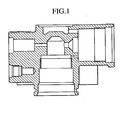
- Fig. 1 shows the cross-sectional shape of a pump body made of an aluminum alloy.
- the pump body is provided with a fuel suction passage, a fuel discharge passage, a fuel passage hole, a fixing bolt hole for fixing the pump body to the engine and the like.
- the pump body includes a suction damper, a solenoid for a discharge quantity control and a pump mechanism (consisting of, for example, a cylinder and a plunger) in order to function as a fuel pump.
- the aluminum die casting is a casting system for injecting a molten alloy (e.g., an aluminum alloy) into a die under a high pressure, and it is excellent in productivity.
- a fabricating process by the aluminum die casting involves in sequence processes for an aluminum alloy ingot, a dissolved material, a cast material, an as-cast material, a machine-finished material, and finally, a pump body. In this process, the as-cast material for the pump body is shaped in such a manner as to reduce a machining margin as possible.
- the aluminum alloy in this case there can be used, for example, a twelfth aluminum alloy die casting (JIS ADC 12).
- JIS ADC 12 twelfth aluminum alloy die casting
- the pump body is subjected to machining after forging or only to machining, to be thus fabricated in a final shape.
- a coating film plated with Ni-P or a Ni-P based material is formed on the pump body, which has been fabricated in the above-described process.
- the plated coating film is made of the Ni-P or the Ni-P based material.
- the Ni-P based material include metals such as Co and W, inorganic compounds such as SiC, BN and PTFE, and an organic material such as B.
- the kind of Ni-P based material is not particularly restricted to the above-listed materials as long as it can be alloyed with or dispersed in the plated coating film.
- a coating film plated with Ni-P or a Ni-P based material should be formed by an electroless method.
- a coating film is essentially required to be formed even at such a portion, and further, the thickness of the plated coating film need be as uniform as possible.
- a plating method by electric energy is undesirable because the plated coating film cannot be formed at the complicated and narrow portion in the fuel passage due to a non-uniform in electric field distribution attributable to a shape effect, or the plated coating film is liable to become non-uniform even if it can be formed.
- the metal serves as a catalyst, thereby generating dehydrogenation decomposition.
- the produced hydrogen atom is adsorbed to the metallic surface of the catalyst, thereby forming a condensed layer, which is then activated.
- the condensed layer is brought into contact with a positive ion of nickel in the plating solution, so that nickel is reduced to metal, to be deposited on the metallic surface of the catalyst (i.e., a base member).
- the activated hydrogen atom on the metallic surface of the catalyst reacts with the negative ion of hypophosphite in the plating solution, and then, phosphor contained in the hypophosphite is reduced to be alloyed with nickel.
- This deposited nickel serves as the catalyst, and thus, the above-described nickel reducing plating reaction continuously proceeds. That is to say, the electroless Ni-P plating is featured in that the plating continuously proceeds owing to the self-catalysis of nickel. Consequently, the plated coating film can be uniformly formed if there is a clearance through which the plating solution can pass. Moreover, since the thickness of the plated coating film is proportional to a plating period of time, the thickness can be managed by controlling the period of time.
- the plated coating film is essentially required to be uniformly formed over the entire surface of the pump body. Therefore, in the plating process, it is important that the entire surface of the pump body should be brought into contact with the plating solution, and that the plating solution should be circulated without any retention.
- the pump body is disposed (or suspended) such that no air sump is generated inside of various kinds of holes formed in at least the fuel passage of the pump body, and that various kinds of holes formed as the fuel passage, which is an important portion in the pump body, are through holes.
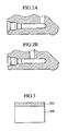
- the plating solution may be retained in the case of a so-called no-go hole (i.e., a hole at which another hole is bored in the vicinity of not a short portion of the passage but the center of the passage, as shown in Fig. 2B ).
- the uniform plated coating film is formed by connecting the holes to each other in the vicinity of the short portion of each of the various kinds of holes, as shown in Fig. 2A , so as to prevent any retention of the plating solution.
- the circulation of the plating solution over the entire surface of the pump body without any retention is essentially required to enable the deposition by the self-catalysis of the Ni-P or the Ni-P based material to, continuously proceed. If the retention occurs, the deposition by the self-catalysis in the limited quantity of the plating solution comes to an end, and the deposition thereafter is stopped. Therefore, the thickness of the plated coating film cannot be increased. As a consequence, the thickness becomes non-uniform.
- the pump body is allowed to be moved in the plating solution, for example, vertically, laterally or rotationally so as to fluidize the plating solution as one method for circulating the plating solution over the entire surface of the pump body without any retention.
- the aluminum alloy casting material JIS ADC 12 was used, a Ni-P plated coating film was formed in a thickness of 15 ⁇ m (a thickness distribution of ⁇ 2 ⁇ m) over the entire surface of a pump body 100.
- the concentration of P contained in the Ni-P plating solution was about 11% by weight.
- Figs. 3 to 6 illustrate examples of the surface structure of a fuel pump.
- Fig. 3 illustrates the surface structure in which a plated coating film 501 is formed on a base member 500 made of an aluminum alloy.
- Fig. 4 illustrates the surface structure in which a plated coating film 501 and an intermediate layer 502 are formed on a base member 500 made of an aluminum alloy.
- Fig. 5 illustrates the surface structure in which a plated coating film 501 and an outer layer 503 are formed on a base member 500 made of an aluminum alloy.
- Fig. 6 illustrates the surface structure in which a plated coating film 501 is formed on a base member 500 made of an aluminum alloy, and further, deficient portions such as pores in the plated coating film 501 are coated with a sealing layer 504.
- the intermediate layer 502 has the function of enhancing the adhesion to the plated coating film 501 or improving corrosion resistance.
- the intermediate layer 502 for enhancing the adhesion is made of Ni.
- An oxide coating film or a chromate coating film is used in order to improve the corrosion resistance. It is desirable that a fine coating film formed in water at a high temperature under a high pressure should be used as the oxide coating film.
- the outer layer 503 has the function of improving the corrosion resistance of the plated coating film 501.
- the material of the outer layer 503 is chromate.
- the sealing layer 504 is adapted to seal the deficient portions of the plated coating film 501, and has the function of improving the corrosion resistance.
- the sealing layer 504 is formed of an oxide coating film or a chromate coating film. It is desirable that a fine coating film formed in water at a high temperature under a high pressure should be used as the oxide coating film.
- the coating film formed by the electroless plating was subjected to heat treatment so as to increase the hardness of the coating film and enhance the adhesion between the base member and the coating film, thereby enhancing cavitation resistance.
- the details will be described later.
- the heat treatment of the plated coating film was performed at a temperature of 200°C for 1.5 hours in the atmosphere. Consequently, the hardness of the Ni-P plated coating film was increased from 520 HV without any heat treatment to as high as 600 HV after the heat treatment.
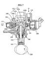
- a radial plunger fuel pump fabricated by the above-described fabricating method in reference to Fig. 7 , which is a cross-sectional view.
- the Ni-P plating is uniformly applied to the pump body 100 made of the aluminum material in the above-described process.
- component parts in contact with fuel in the fuel pump were made of an aluminum material.
- the pump body 100, a pressurizing chamber 112, a fuel suction passage 110, a fuel discharge passage 111 and the like are assumed to be used in contact with gasoline containing alcohol such as methyl alcohol or ethyl alcohol, various kinds of gasoline additives or deteriorated gasoline (of course, it is to be understood that the fuel may contain only gasoline).
- the fuel passage there are formed, as the fuel passage, the fuel suction passage 110, a suction hole 105a, a pump chamber 112a, a discharge edge 106a and the fuel discharge passage 111.
- a suction valve 105 is interposed between the fuel suction passage 110 and the suction hole 105a; in the meantime, a discharge valve 106 is interposed between the fuel discharge passage 111 and the discharge edge 106a.
- Each of the suction valve 105 and the discharge valve 106 is a check valve for limiting the passing direction of the fuel.
- the pressurizing chamber 112 is configured by including the pump chamber 112a, the suction hole 105a and the discharge edge 106a.
- the pressurizing chamber 112 is formed in a region defined by the pump body 100, a plunger 102, the suction valve 105 and the discharge valve 106.
- the plunger 102 is configured in such a manner as to be brought into press-contact with a drive cam 200 via a lifter 103, so as to convert an oscillating motion of the drive cam 200 into a reciprocating motion, thereby changing the volume of the pressurizing chamber 112.
- the pump body 100 is brought into press-contact with a suction valve holder 105b and a discharge valve holder 106b, respectively, and further, a cylinder 108 and the pump body 100 are brought into press-contact with each other via a protector 120.
- the protector 120 is useful for preventing the base member of the pump body or the like from being broken caused by occurrence of cavitation, described later.
- the use of the protector 120 may be selected depending upon the condition of the pump to be used. Although the protector 120 dare be provided, no use of the protector 120 may be selected as long as the NiP plating is made thick and the corrosion resistance and cavitation resistance can be sufficiently achieved.
- the Ni-P plating is applied to the pump body in the radial plunger fuel pump, it is possible to suppress a direct contact between the soft aluminum base member and the protector 120 which may occur when the protector 120 (inclusive of a press-contact member such as the cylinder 108, hereinafter in the same manner) is brought into press-contact, and further, to suppress generation of powder of the soft base member when the protector 120 is brought into press-contact.
- the pump body is made of the aluminum material and the press-contact member is made of a member harder than the aluminum material (for example, JIS SUS 304), the press-contact member can be embedded in the pores so as to enhance the sealing property, and additionally, the Ni-P plated layer having a middle hardness is interposed between the aluminum material and the harder press-contact member, thereby preventing any excessive deformation of the aluminum material more than required during the press-contact.
- the protector 120 can be used also in other press-contact portions, thereby producing the same effect as that described above.
- the fuel i.e., the gasoline is supplied via the suction valve 105, and then, is introduced into the pressurizing chamber 112.
- the operation of the suction valve 105 depends upon that of a solenoid 300. Namely, when the solenoid 300 is not operated (not energized), an energizing force is applied in a direction in which the suction valve 105 is opened; in contrast, when the solenoid 300 is operated (energized), the suction valve 105 serves as a free valve which is opened or closed in synchronism with the reciprocating motion of the plunger 102.
- the suction valve 105 is closed during a compressing process of the plunger 102, the inner pressure inside of the pressurizing chamber 112 is increased to thus automatically open the discharge valve 106, so that the fuel is press-fed to the fuel discharge passage.
- Fig. 8 illustrates the corrosion resistance of various kinds of materials and the aluminum material plated with Ni-P, which is one surface treatment according to the present invention.
- a solution containing 13.5% by volume of ethyl alcohol in water and having an acidic ion concentration of 0.13 mg KOH/g in the total acid value was used in the environment of a corrosion test.
- Fig. 8 is a graph illustrating a open circuit potential and a pitting corrosion potential in the solution, wherein the corrosion resistance is more excellent as both of the open circuit potential and the pitting corrosion potential are higher.
- a value of an JIS SUS 304 stainless steel to be generally used as a material excellent in corrosion resistance is plotted in a region in which both of the open circuit potential and the pitting corrosion potential are high, and as a result, it is found that the JIS SUS 304 stainless steel is excellent in corrosion resistance.
- a value of an aluminum alloy ductile material JIS A 1012 excellent in corrosion resistance is plotted in a region in which both of the open circuit potential and the pitting corrosion potential are lower, and as a result, it is revealed that the aluminum alloy flatting material JIS A 1012 is poor in corrosion resistance.
- an aluminum alloy casting material JIS ADC 12 is plotted in a region in which both of the open circuit potential and the pitting corrosion potential are much lower, and as a result, it is found that the aluminum alloy casting material JIS ADC 12 is poorer in corrosion resistance.
- Values of an alloy tool steel JIS SKD 11 as an iron-based material, a spheroidal graphite cast iron JIS FCD 400 and a carbon steel JIS S45C are plotted in a region in which both of the open circuit potential and the pitting corrosion potential are low, wherein the corrosion resistance is slightly better since the open circuit potential is higher than that of the aluminum alloy casting material JIS ADC 12. This result revealed that the aluminum alloy casting material JIS ADC 12 was one of the materials poor in corrosion resistance.
- a material prepared by plating the aluminum alloy casting material JIS ADC 12 with Ni-P was remarkably higher in open circuit potential and pitting corrosion potential than the materials except for SUS, and therefore, was excellent in corrosion resistance. Consequently, the material prepared by plating the aluminum alloy casting material JIS ADC 12 with Ni-P has great advantages from the viewpoints of a light weight and easy machining, and thus, it is appreciated to be a very useful material, although it is slightly poorer in corrosion resistance than JIS SUS 304.
- Fig. 9 is a graph illustrating a volume reduction quantity due to cavitation attrition of various kinds of materials by a magnetostrictive vibration destructive testing device.
- the measurement by the magnetostrictive vibration destructive testing device was achieved by comparing the attrition degrees of various kinds of materials caused by the cavitation in pure water at a frequency of 20 kHz, an amplitude of 22.4 ⁇ m and a temperature of 20°C.
- Fig. 9 shows the result that the volume reduction quantity is great with respect to soft aluminum based materials (see JIS ADC 12 and the like) while the volume reduction quantity is small with respect to hard iron steel, cast iron and stainless steel.
- JIS ADC 12 is plated with Ni-P or Ni-P-SiC
- the volume reduction quantity of JIS ADC 12 becomes as small as those of the iron steel and cast iron (see "JIS ADC 12 + Ni-P" and the like).
- Fig. 10 is a graph illustrating the influence by the heat treatment using the Ni-P plated coating film on the cavitation attrition by the magnetostrictive vibration destructive testing device.
- the Ni-P plated coating film becomes harder by the heat treatment. That is to say, the hardness of the Ni-P plated coating film is about 500 HV only by plating treatment; in contrast, it becomes greater as the temperature of the heat treatment is increased, and thus, about 1000 HV at about 400°C.
- the Ni-P plated layer is subjected to the heat treatment, so that the adhesion between the aluminum material and the Ni-P plated layer can be enhanced, thereby suppressing the attrition caused by the cavitation. From Fig.
- Fig. 11 photographically illustrates the test results of the influence of the Ni-P plating on the cavitation, corresponding to Figs. 9 and 10 .
- samples subjected to the heat treatment at 200°C for 1 hour could not show any attrition caused by the cavitation even if 50 minutes and 80 minutes elapsed.
- a sample subjected to no heat treatment showed the attrition caused by the cavitation after a lapse of a test time of no more than 50 minutes.
- Fig. 11 shows that the hardness and adhesion of the plated coating film are enhanced owing to the heat treatment, so that the cavitation resistance can be remarkably improved.
- it is effective to subject the Ni-P plated coating film to the heat treatment in order to enhance the cavitation resistance of the Ni-P plated coating film.
- the heat treatment need be performed at a low temperature.
- the higher hardness is desired in view of the cavitation resistance.
- the heating temperature is increased in order to increase the hardness of the plated coating film, the plated coating film is crystallized (at a crystallization temperature of about 220°C), thereby generating a granular boundary of crystals. Due to such a granular field, the fuel containing alcohol corrodes the aluminum base member, thereby possibly deteriorating the corrosion resistance by contraries. Thus, it is effective that the temperature of the heat treatment cannot extremely exceed the crystallization temperature of the Ni-P plated coating film, which is kept in an amorphous state.
- the heat treatment should be performed at a temperature of 300°C or lower (about 800 HV). Additionally, it is effective that the amorphous state is kept by performing the heat treatment at a temperature of 220°C or lower (about 650 HV).
- the plated coating film may be possibly peeled off by the corrosion, the cavitation or the like, and consequently, the base member may be possibly exposed and corroded before the fuel pump approaches the end of its lifetime.
- the thickness of the plated coating film is 50 ⁇ m or more, a difference in dimension between a screw and a screw hole cannot be negligible, although the thickness is effective from the viewpoints of the corrosion resistance, the cavitation resistance and the fitting of the screw into the screw hole, thereby making it difficult to fix the press-contact component parts.
- the thickness of the plated coating film is desirable to be about 25 ⁇ m.
- the reasons why the Ni-P plated coating film is effective for fitting of the screw into the screw hole are that: the surface of the aluminum material becomes smooth by the Ni-P plating even if the surface is rough; the shape of the screw hole becomes more stable in comparison with the fitting of the screw into the screw hole formed at the aluminum material subjected to no surface treatment when the hardness of the Ni-P plated layer becomes high; and the generation of aluminum powder caused by the friction between aluminum and the press-contact member in screwing can be suppressed.
- the electroless plating treatment in which both of the screw hole portion and the fuel passage can be subjected to the plating treatment at one time, is very effective.
- the coating film plated with the Ni-P or the Ni-P based material is formed in the fuel passage in the fuel pump, the occurrence of the corrosion and the attrition caused by the cavitation and erosion can be suppressed, and therefore, their resistance against the environment could be improved.
- the fuel pump made of aluminum or the aluminum alloy can be obtained for the first time, thereby achieving the fuel pump having the complicated shape with ease. It is to be understood that the above described effects can be produced with either aluminum singly or the aluminum alloy as long as the material is aluminum.
- Fig. 12 shows a radial plunger fuel pump having, at a part of a low pressure chamber of a pump body partitioning a pressurizing chamber and the low pressure chamber, a portion at which an aluminum material is exposed by peeling off plating or no plating treatment dare be performed.
- the corrosion resistance of the portion, at which the aluminum material is exposed is made lowest among other portions, that is, the low pressure chamber and the pressurizing chamber can communicate with each other prior to other corroded portions, thereby preventing other serious deficiencies caused by corrosion although there may occur a deficient increase in pressure in the relatively low-risk situation.
- Fig. 13 is a cross-sectional view showing a swash plate type axial plunger fuel pump (a three-cylinder type).
- the swash plate type axial plunger fuel pump comprises a shaft 1 for transmitting drive force to the inside of a housing from the outside; a swash plate 9 for converting a rotating motion into an oscillating motion via the shaft; a plunger 11 for converting a rotating motion of the swash plate 9 into a reciprocating motion; and a cylinder bore 13 for sucking and discharging fuel in combination with the plunger 11.
- the shaft 1 is integrated with the swash plate 9 which extends in a radial direction and is formed at the end surface thereof into a slant plane.
- a slipper 10 is brought into contact with the swash plate 9.
- the slipper 10 is formed into a spherical shape on the other side thereof, and thus, is supported by the spherical surface formed at the plunger 11 which slides inside of the cylinder bore 13. The oscillating motion generated when the swash plate 9 is rotated is converted into the reciprocating motion of the plunger 11.
- a pump chamber 14 is defined inside of a cylinder 12 by the plurality of cylinder bores 13 and plungers 11.
- a suction space 15 communicating with each of the plungers 11 at the center portion of the cylinder 12, so as to supply the fuel to the pump chamber 14.
- a fuel pipeline outside of the pump is fixed to a rear body 20.
- a suction chamber 30 at the center portion of the rear body 20 is connected to the suction space 15 formed in the cylinder 12 through a suction passage inside of the rear body 20.
- the plunger 11 incorporates therein a suction valve 24 (i.e., a check valve) for sucking the fuel, a ball 21, a spring 22 and a stopper 23 for supporting the spring 22.
- a plunger spring 25 is inserted for the purpose of pressing the plunger 11 against the swash plate 9 all the time so as to allow the plunger 11 together with the slipper 10 to follow the swash plate 9.
- a communication path A 16 to the suction valve 24 disposed inside of the plunger 11 is formed as a communication path to a countersink 51 and the suction space 15 disposed in the cylinder bore 13.
- the countersink 51 has a diameter greater than the cylinder bore 13, and is formed down to such a depth as to achieve the communication between an introducing hole 19 and the countersink 51 also when the volume of the pump chamber 14 is sufficiently reduced (when the position of the plunger is located at a top dead center) in such a manner that the fuel can be introduced into the plunger 11 all the time.
- an aluminum material is used in the rear body 20 as a component part which is brought into contact with the fuel. Corrosion resistance is required for the rear body 20 in the case where corrosion may occur caused ty the fuel of gasoline added with methyl alcohol or ethyl alcohol, various kinds of gasoline additives or deteriorated gasoline.
- Other component parts, for example, the cylinder 12 and the cylinder bore 13 are made of a stainless steel and an alloy tool steel, respectively.
- the rear body 20 is provided with a fuel passage consisting of a discharge valve 28, a discharge chamber 29, the suction chamber 30 and the like. Furthermore, the rear body 20 is tightened to a body 5, and air-tightness thereof is secured by an O-ring 31.
- the plated coating film having the structure shown in Fig. 1 was formed over the entire rear body 20 in the fuel pump.
- the Ni-P plated coating film had a concentration of P of about 11% by weight, a thickness of 15 ⁇ m and a thickness distribution of ⁇ 2 ⁇ m.
- the rear body 20 was subjected to heat treatment at a temperature of 250°C for 1 hour in the atmosphere. Consequently, the hardness of the Ni-P plated coating film was increased from about 520 HV without any heat treatment to 657 HV after the heat treatment.
- the coating film plated with the Ni-P or the Ni-P based material is formed in the fuel passage in the fuel pump, the occurrence,of the corrosion and the attrition caused by the cavitation and erosion can be suppressed, and therefore, their resistance against the environment could be improved.
- the fuel pump made of aluminum or the aluminum alloy can be obtained for the first time, thereby achieving the fuel pump having the complicated shape with ease.
- the present invention it is possible to provide the fuel pump for the inter-cylinder direct fuel injection apparatus, having the excellent lifetime by the use of the aluminum material.
Landscapes
- Chemical & Material Sciences (AREA)
- Engineering & Computer Science (AREA)
- Mechanical Engineering (AREA)
- Inorganic Chemistry (AREA)
- Metallurgy (AREA)
- Materials Engineering (AREA)
- Chemical Kinetics & Catalysis (AREA)
- Organic Chemistry (AREA)
- General Engineering & Computer Science (AREA)
- Fuel-Injection Apparatus (AREA)
- Details Of Reciprocating Pumps (AREA)
- Chemically Coating (AREA)
- Other Surface Treatments For Metallic Materials (AREA)
Claims (14)
- Kraftstoffpumpe für eine Zwischenzylinder-Direktkraftstoffeinspritzvorrichtung für einen Benzinmotor, mit:einem Kraftstoffpumpenkörper (100) aus Aluminium oder einer Aluminiumlegierung; undeinem Kraftstoffdurchgang des Kraftstoffpumpenkörpers (100), in welchem im Gebrauch Benzin fließt, dem Alkohol zugegeben oder nicht zugegeben ist, dadurch gekennzeichnet, dassein Beschichtungsfilm (501), der mit Ni-P oder einem Material auf Ni-P-Basis plattiert ist, auf dem Kraftstoffpumpenkörper (100) und dem Kraftstoffdurchgang (105a, 106a, 110, 111, 112a) des Kraftstoffpumpenkörpers (100) für den Benzinmotor ausgebildet ist,und dassder Beschichtungsfilm (501), der mit dem Ni-P oder dem Material auf Ni-P-Basis plattiert ist, mindestens 500 HV beträgt.
- Kraftstoffpumpe für eine Zwischenzylinder-Direktkraftstoffeinspritzvorrichtung nach Anspruch 1, wobei der Beschichtungsfilm (501), der mit dem Ni-P oder dem Material auf Ni-P-Basis plattiert ist, in einer Dicke von mindestens 10 µm ausgebildet ist.
- Kraftstoffpumpe für eine Zwischenzylinder-Direktkraftstoffeinspritzvorrichtung nach Anspruch 1, wobei der Beschichtungsfilm (501), der mit dem Ni-P oder dem Material auf Ni-P-Basis plattiert ist, in einer Dicke von mindestens 10 µm und höchstens 50 µm ausgebildet ist.
- Kraftstoffpumpe für eine Zwischenzylinder-Direktkraftstoffeinspritzvorrichtung nach Anspruch 1, wobei ein Oxidbeschichtungsfilm oder ein Chromatbeschichtungsfilm zwischen dem Aluminium oder der Aluminiumlegierung und dem Beschichtungsfilm (501), der mit dem Ni-P oder dem Material auf Ni-P-Basis plattiert ist, ausgebildet ist.
- Kraftstoffpumpe für eine Zwischenzylinder-Direktkraftstoffeinspritzvorrichtung nach Anspruch 1, wobei ein Oxidbeschichtungsfilm oder ein Chromatbeschichtungsfilm ferner auf dem Aluminium oder der Aluminiumlegierung und dem Beschichtungsfilm (501), der mit dem Ni-P oder dem Material auf Ni-P-Basis plattiert ist, ausgebildet ist.
- Kraftstoffpumpe für eine Zwischenzylinder-Direktkraftstoffeinspritzvorrichtung nach Anspruch 1, wobei der Kraftstoffdurchgang eine Druckkammer (112) und eine Niederdruckkammer einschließt, wobei die Druckkammer (112) und die Niederdruckkammer voneinander über das Aluminium oder die Aluminiumlegierung getrennt sind, und
wobei ein Bereich vorgesehen ist, in dem das Aluminium oder die Aluminiumlegierung in einem Teil, auf der Seite der Niederdruckkammer, des Aluminiums oder der Aluminiumlegierung zum Trennen der Druckkammer (112) und der Niederdruckkammer voneinander freigelegt ist. - Kraftstoffpumpe für eine Zwischenzylinder-Direktkraftstoffeinspritzvorrichtung nach Anspruch 1, wobei der Beschichtungsfilm (501), der mit dem Ni-P oder dem Material auf Ni-P-Basis plattiert ist, amorph ist.
- Kraftstoffpumpe für eine Zwischenzylinder-Direktkraftstoffeinspritzvorrichtung nach mindestens einem der vorhergehenden Ansprüche, ferner mit:einer Abdichtung (504), weiche fehlerhafte Bereiche in dem Beschichtungsfilm (501), der mit Ni-P oder einem Material auf Ni-P-Basis plattiert ist, abdichtet, die auf das Aluminium oder die Aluminiumlegierung angewendet wird; wobeider Pumpenkörper (100) dazu ausgelegt ist, in Kontakt mit einem Presspassungselement (108, 120) zu sein.
- Kraftstoffpumpe für eine Zwischenzylinder-Direktkraftstoffeinspritzvorrichtung nach Anspruch 8, wobei die Abdichtung (504) des Beschichtungsfilms (501), der mit dem Ni-P oder dem Material auf Ni-P-Basis plattiert ist, in einer Dicke von mindestens 10 µm ausgebildet ist.
- Kraftstoffpumpe für eine Zwischenzylinder-Direktkraftstoffeinspritzvorrichtung nach Anspruch 8, wobei die Abdichtung (504) des Beschichtungsfilms (501), der mit dem Ni-P oder dem Material auf Ni-P-Basis plattiert ist, in einer Dicke von mindestens 10 µm und höchstens 50 µm ausgebildet ist.
- Kraftstoffpumpe für eine Zwischenzylinder-Direktkraftstoffeinspritzvorrichtung nach Anspruch 8, wobei die Abdichtung (504) des Beschichtungsfilms (501), der mit dem Ni-P oder dem Material auf Ni-P-Basis plattiert ist, mindestens 500 HV beträgt.
- Kraftstoffpumpe für eine Zwischenzylinder-Direktkraftstoffeinspritzvorrichtung nach Anspruch 8, wobei ein Oxidbeschichtungsfilm oder ein Chromatbeschichtungsfilm zwischen dem Pumpenkörper (100) aus dem Aluminium oder der Aluminiumlegierung und der Abdichtung (504) des Beschichtungsfilms (501) ausgebildet ist, der mit dem Ni-P oder dem Material auf Ni-P-Basis plattiert ist.
- Kraftstoffpumpe für eine Zwischenzylinder-Direktkraftstoffeinspritzvorrichtung nach Anspruch 8, wobei ein Oxidbeschichtungsfilm oder ein Chromatbeschichtungsfilm ferner auf dem Pumpenkörper (100) aus dem Aluminium oder der Aluminiumlegierung und auf der Abdichtung (504) des Beschichtungsfilms (501) ausgebildet ist, der mit dem Ni-P oder dem Material auf Ni-P-Basis plattiert ist.
- Kraftstoffpumpe für eine Zwischenzylinder-Direktkraftstoffeinspritzvorrichtung nach Anspruch 13, wobei der Beschichtungsfilm (501), der mit dem Ni-P oder dem Material auf Ni-P-Basis plattiert ist, amorph ist.
Applications Claiming Priority (2)
| Application Number | Priority Date | Filing Date | Title |
|---|---|---|---|
| JP2002196653 | 2002-07-05 | ||
| JP2002196653A JP3912206B2 (ja) | 2002-07-05 | 2002-07-05 | 筒内直接燃料噴射装置用燃料ポンプ |
Publications (3)
| Publication Number | Publication Date |
|---|---|
| EP1378664A2 EP1378664A2 (de) | 2004-01-07 |
| EP1378664A3 EP1378664A3 (de) | 2009-03-11 |
| EP1378664B1 true EP1378664B1 (de) | 2013-03-27 |
Family
ID=29720307
Family Applications (1)
| Application Number | Title | Priority Date | Filing Date |
|---|---|---|---|
| EP20020024405 Expired - Lifetime EP1378664B1 (de) | 2002-07-05 | 2002-10-28 | Kraftstoffpumpe für Direkt-Kraftstoffeinspritzungsgerät |
Country Status (3)
| Country | Link |
|---|---|
| US (2) | US6895992B2 (de) |
| EP (1) | EP1378664B1 (de) |
| JP (1) | JP3912206B2 (de) |
Families Citing this family (13)
| Publication number | Priority date | Publication date | Assignee | Title |
|---|---|---|---|---|
| US20040052664A1 (en) * | 2001-01-05 | 2004-03-18 | Atsuji Saito | High-pressure fuel feed pump |
| US7857605B2 (en) * | 2006-06-29 | 2010-12-28 | Caterpillar Inc | Inlet throttle controlled liquid pump with cavitation damage avoidance feature |
| JP2008064013A (ja) * | 2006-09-07 | 2008-03-21 | Hitachi Ltd | 高圧燃料供給ポンプ |
| JP2008111396A (ja) * | 2006-10-31 | 2008-05-15 | Denso Corp | 高圧燃料ポンプの製造方法 |
| US7811370B2 (en) * | 2007-04-24 | 2010-10-12 | Xerox Corporation | Phase change ink compositions |
| JP2009019592A (ja) * | 2007-07-12 | 2009-01-29 | Aisan Ind Co Ltd | 燃料噴射弁 |
| JP5559962B2 (ja) * | 2008-09-05 | 2014-07-23 | 日立オートモティブシステムズ株式会社 | 燃料噴射弁及びノズルの加工方法 |
| CN103717873B (zh) * | 2011-08-01 | 2017-06-27 | 丰田自动车株式会社 | 燃料泵 |
| JP6180741B2 (ja) * | 2013-01-15 | 2017-08-16 | 日立オートモティブシステムズ株式会社 | 電磁駆動型の吸入弁を備えた高圧燃料供給ポンプ |
| WO2016147310A1 (ja) * | 2015-03-17 | 2016-09-22 | 三菱重工業株式会社 | 回転機械の羽根車、コンプレッサ、過給機及び回転機械の羽根車の製造方法 |
| JP6337874B2 (ja) * | 2015-12-03 | 2018-06-06 | 株式会社デンソー | 高圧ポンプ |
| DE102016220610A1 (de) * | 2016-10-20 | 2018-04-26 | Robert Bosch Gmbh | Hochdruckpumpe für ein Kraftstoffeinspritzsystem |
| US11661913B2 (en) | 2021-05-17 | 2023-05-30 | Delphi Technologies Ip Limited | Fuel pump with inlet valve assembly |
Family Cites Families (98)
| Publication number | Priority date | Publication date | Assignee | Title |
|---|---|---|---|---|
| US3077421A (en) * | 1961-03-13 | 1963-02-12 | Gen Am Transport | Processes of producing tin-nickelphosphorus coatings |
| US3956259A (en) * | 1973-01-30 | 1976-05-11 | Baxter Laboratories, Inc. | Fractionation of blood using block copolymer of ethylene oxide and polyoxypropylene polymer to recover fraction suitable for organ perfusate |
| US3925344A (en) * | 1973-04-11 | 1975-12-09 | Community Blood Council | Plasma protein substitute |
| US4179337A (en) * | 1973-07-20 | 1979-12-18 | Davis Frank F | Non-immunogenic polypeptides |
| DE2449885C3 (de) * | 1974-10-21 | 1980-04-30 | Biotest-Serum-Institut Gmbh, 6000 Frankfurt | Verfahren zur Herstellung von chemisch modifizierten haltbaren Hämoglobinpräparaten sowie das nach diesem Verfahren hergestellte modifizierte Hämoglobinpräparat |
| US4001401A (en) * | 1975-02-02 | 1977-01-04 | Alza Corporation | Blood substitute and blood plasma expander comprising polyhemoglobin |
| US4061736A (en) * | 1975-02-02 | 1977-12-06 | Alza Corporation | Pharmaceutically acceptable intramolecularly cross-linked, stromal-free hemoglobin |
| US4001200A (en) * | 1975-02-27 | 1977-01-04 | Alza Corporation | Novel polymerized, cross-linked, stromal-free hemoglobin |
| US4053590A (en) * | 1975-02-27 | 1977-10-11 | Alza Corporation | Compositions of matter comprising macromolecular hemoglobin |
| CA1055932A (en) * | 1975-10-22 | 1979-06-05 | Hematech Inc. | Blood substitute based on hemoglobin |
| GB1578776A (en) * | 1976-06-10 | 1980-11-12 | Univ Illinois | Hemoglobin liposome and method of making the same |
| JPS5329908A (en) * | 1976-08-27 | 1978-03-20 | Green Cross Corp:The | Immobilized haptoglobin preparation |
| US4316093A (en) * | 1979-02-12 | 1982-02-16 | International Business Machines Corporation | Sub-100A range line width pattern fabrication |
| JPS6023084B2 (ja) * | 1979-07-11 | 1985-06-05 | 味の素株式会社 | 代用血液 |
| US4650417A (en) * | 1980-01-21 | 1987-03-17 | Robert Schwartz | Denture forming device |
| JPS5716815A (en) * | 1980-07-02 | 1982-01-28 | Ajinomoto Co Inc | Oxygen transporting agent for artificial blood |
| US4401652A (en) * | 1980-12-31 | 1983-08-30 | Allied Corporation | Process for the preparation of stroma-free hemoglobin solutions |
| JPS57206622A (en) * | 1981-06-10 | 1982-12-18 | Ajinomoto Co Inc | Blood substitute |
| US4532130A (en) * | 1981-07-06 | 1985-07-30 | Rush-Presbyterian-St. Luke's Medical Center | Preparation of synthetic frythrocytes |
| DE3130770C2 (de) * | 1981-08-04 | 1986-06-19 | Biotest-Serum-Institut Gmbh, 6000 Frankfurt | Verfahren zur Gewinnung von hepatitissicheren, sterilen, pyrogenfreien und stromafreien Hämoglobinlösungen |
| US4473496A (en) * | 1981-09-14 | 1984-09-25 | The United States Of America As Represented By The Secretary Of The Army | Intramolecularly crosslinked hemoglobin |
| DE3144705C2 (de) * | 1981-11-11 | 1983-12-08 | Biotest-Serum-Institut Gmbh, 6000 Frankfurt | Verfahren zur Herstellung eines lagerstabilen, vernetzten Hämoglobinpräparates mit hoher Sauerstoff-Transportkapazität, sowie das nach diesem Verfahren hergestellte Hämoglobinpräparat |
| US4473494A (en) * | 1983-05-04 | 1984-09-25 | The United States Of America As Represented By The Secretary Of The Army | Preparation of stroma-free, non-heme protein-free hemoglobin |
| US4529719A (en) * | 1983-05-04 | 1985-07-16 | Tye Ross W | Modified crosslinked stroma-free tetrameric hemoglobin |
| GB8328917D0 (en) * | 1983-10-28 | 1983-11-30 | Fisons Plc | Blood substitute |
| US5281579A (en) * | 1984-03-23 | 1994-01-25 | Baxter International Inc. | Purified virus-free hemoglobin solutions and method for making same |
| US4831012A (en) * | 1984-03-23 | 1989-05-16 | Baxter International Inc. | Purified hemoglobin solutions and method for making same |
| DE3412144A1 (de) * | 1984-03-31 | 1985-10-10 | Biotest Pharma GmbH, 6000 Frankfurt | Verfahren zur herstellung hochgereinigter, stromafreier, hepatitissicherer human- und tierhaemoglobinloesungen |
| US4738952A (en) * | 1984-04-27 | 1988-04-19 | Synthetic Blood Corporation | Substitute for human blood and a method of making the same |
| US4600531A (en) * | 1984-06-27 | 1986-07-15 | University Of Iowa Research Foundation | Production of alpha-alpha cross-linked hemoglobins in high yield |
| US4598064A (en) * | 1984-06-27 | 1986-07-01 | University Of Iowa Research Foundation | Alpha-alpha cross-linked hemoglobins |
| US4584130A (en) * | 1985-03-29 | 1986-04-22 | University Of Maryland | Intramolecularly cross-linked hemoglobin and method of preparation |
| EP0206448B1 (de) * | 1985-06-19 | 1990-11-14 | Ajinomoto Co., Inc. | Hämoglobin, das an ein Poly(alkenylenoxid) gebunden ist |
| US4987154A (en) * | 1986-01-14 | 1991-01-22 | Alliance Pharmaceutical Corp. | Biocompatible, stable and concentrated fluorocarbon emulsions for contrast enhancement and oxygen transport in internal animal use |
| US5080885A (en) * | 1986-01-14 | 1992-01-14 | Alliance Pharmaceutical Corp. | Brominated perfluorocarbon emulsions for internal animal use for contrast enhancement and oxygen transport |
| US5684050A (en) * | 1986-01-24 | 1997-11-04 | Hemagen/Pfc | Stable emulsions of highly fluorinated organic compounds |
| US4826811A (en) * | 1986-06-20 | 1989-05-02 | Northfield Laboratories, Inc. | Acellular red blood cell substitute |
| US5194590A (en) * | 1986-06-20 | 1993-03-16 | Northfield Laboratories, Inc. | Acellular red blood cell substitute |
| US5464814A (en) * | 1986-06-20 | 1995-11-07 | Northfield Laboratories, Inc. | Acellular red blood cell substitute |
| US4911929A (en) * | 1986-08-29 | 1990-03-27 | The United States Of America As Represented By The Secretary Of The Navy | Blood substitute comprising liposome-encapsulated hemoglobin |
| US4730936A (en) * | 1986-10-10 | 1988-03-15 | The United States Of America As Represented By The Secretary Of The Air Force | Gas driven system for preparing large volumes of non-oxidized, pyridoxylated, polymerized stroma-free hemoglobin solution for use as a blood substitute |
| DE3636590A1 (de) * | 1986-10-28 | 1988-05-26 | Braun Melsungen Ag | Blutersatzmittel |
| US5084558A (en) * | 1987-10-13 | 1992-01-28 | Biopure Corporation | Extra pure semi-synthetic blood substitute |
| CA1312009C (en) * | 1986-11-10 | 1992-12-29 | Carl W. Rausch | Extra pure semi-synthetic blood substitute |
| GB8710598D0 (en) * | 1987-05-05 | 1987-06-10 | Star Medical Diagnostics Ltd | Hemoglobin based blood substitute |
| GB8711614D0 (en) * | 1987-05-16 | 1987-06-24 | Medical Res Council | Proteins |
| US5449759A (en) * | 1987-05-16 | 1995-09-12 | Somatogen, Inc. | Hemoglobins with intersubunit desulfide bonds |
| US4861867A (en) * | 1988-02-03 | 1989-08-29 | Baxter International, Inc. | Purified hemoglobin solutions and method for making same |
| US4900780A (en) * | 1988-05-25 | 1990-02-13 | Masonic Medical Research Laboratory | Acellular resuscitative fluid |
| CA1338244C (en) * | 1988-08-17 | 1996-04-09 | Xiang-Fu Wu | Purification of hemoglobin and methemoglobin by bioselective elution |
| US5061688A (en) * | 1988-08-19 | 1991-10-29 | Illinois Institute Of Technology | Hemoglobin multiple emulsion |
| US5128452A (en) * | 1989-04-19 | 1992-07-07 | Baxter International Inc. | Process for the production of crosslinked hemoglobin in the presence of sodium tripolyphosphate |
| US5545727A (en) * | 1989-05-10 | 1996-08-13 | Somatogen, Inc. | DNA encoding fused di-alpha globins and production of pseudotetrameric hemoglobin |
| US5599907A (en) * | 1989-05-10 | 1997-02-04 | Somatogen, Inc. | Production and use of multimeric hemoglobins |
| US5650388A (en) * | 1989-11-22 | 1997-07-22 | Enzon, Inc. | Fractionated polyalkylene oxide-conjugated hemoglobin solutions |
| US5234903A (en) * | 1989-11-22 | 1993-08-10 | Enzon, Inc. | Chemically modified hemoglobin as an effective, stable non-immunogenic red blood cell substitute |
| US5312808A (en) * | 1989-11-22 | 1994-05-17 | Enzon, Inc. | Fractionation of polyalkylene oxide-conjugated hemoglobin solutions |
| US5386014A (en) * | 1989-11-22 | 1995-01-31 | Enzon, Inc. | Chemically modified hemoglobin as an effective, stable, non-immunogenic red blood cell substitute |
| US5041615A (en) * | 1989-12-05 | 1991-08-20 | Baxter International Inc. | Preparation of bis(salicyl) diesters |
| US5239061A (en) * | 1990-06-20 | 1993-08-24 | Research Corporation Technologies, Inc. | Modified human hemoglobin, blood substitutes containing the same, and vectors for expressing the modified hemoglobin |
| US5352773A (en) * | 1990-08-06 | 1994-10-04 | Baxter International Inc. | Stable hemoglobin based composition and method to store same |
| US5248766A (en) * | 1990-08-17 | 1993-09-28 | Baxter International Inc. | Oxirane-modified hemoglobin based composition |
| US5252714A (en) * | 1990-11-28 | 1993-10-12 | The University Of Alabama In Huntsville | Preparation and use of polyethylene glycol propionaldehyde |
| US5114932A (en) * | 1990-11-30 | 1992-05-19 | Runge Thomas M | Hyperosmolar oxyreplete hemosubstitute |
| CA2066374C (en) * | 1991-04-19 | 2002-01-29 | Paul E. Segall | Solution for perfusing primates |
| US5295944A (en) * | 1991-05-14 | 1994-03-22 | Dana-Farber Cancer Institute | Method for treating a tumor with ionizing radiation |
| US5250665A (en) * | 1991-05-31 | 1993-10-05 | The University Of Toronto Innovations Foundation | Specifically β-β cross-linked hemoglobins and method of preparation |
| US5349054A (en) * | 1991-08-15 | 1994-09-20 | Duke University | Activated benzenepentacarboxylate-crosslinked low oxygen affinity hemoglobin |
| US5334705A (en) * | 1991-08-15 | 1994-08-02 | Duke University | Benzenetricarboxylate derivative-crosslinked low oxygen affinity hemoglobin |
| US5334706A (en) * | 1992-01-30 | 1994-08-02 | Baxter International | Administration of low dose hemoglobin to increase perfusion |
| US5200323A (en) * | 1992-01-31 | 1993-04-06 | Mcgill University | In vitro method to determine the safety of modified hemoglobin blood substitutes for human prior to clinical use |
| US5296466A (en) * | 1992-02-19 | 1994-03-22 | Board Of Regents, The University Of Texas System | Inhibition of nitric oxide-mediated hypotension and septic shock with iron-containing hemoprotein |
| US5344393A (en) * | 1992-02-28 | 1994-09-06 | Alliance Pharmaceutical Corp. | Use of synthetic oxygen carriers to facilitate oxygen delivery |
| US5264555A (en) * | 1992-07-14 | 1993-11-23 | Enzon, Inc. | Process for hemoglobin extraction and purification |
| JPH0748681A (ja) | 1992-07-15 | 1995-02-21 | Nippon Tokushu Arumaito Kogyo Kk | 無電解メッキと電気メッキを併用したメッキ方法 |
| US5628930A (en) * | 1992-10-27 | 1997-05-13 | Alliance Pharmaceutical Corp. | Stabilization of fluorocarbon emulsions |
| US5558855A (en) * | 1993-01-25 | 1996-09-24 | Sonus Pharmaceuticals | Phase shift colloids as ultrasound contrast agents |
| ES2095751T3 (es) * | 1993-03-16 | 1997-02-16 | Hemosol Inc | Regulacion selectiva de hemoglobinas mediante sacaridos de anillo abierto oxidados. |
| US5635538A (en) * | 1993-03-16 | 1997-06-03 | Alliance Pharmaceutical Corp. | Fluorocarbon emulsions with reduced pulmonary gas-trapping properties |
| US5554638A (en) * | 1993-05-24 | 1996-09-10 | Duke University | Methods for improving therapeutic effectiveness of agents for the treatment of solid tumors and other disorders |
| AU681675B2 (en) * | 1993-06-04 | 1997-09-04 | Biotime, Inc. | Plasma-like solution |
| US5407428A (en) * | 1993-06-04 | 1995-04-18 | Biotime, Inc. | Solutions for use as plasma expanders and substitutes |
| US5578564A (en) * | 1993-07-23 | 1996-11-26 | Somatogen, Inc. | Nickel-free hemoglobin and methods for producing such hemoglobin |
| TW381022B (en) * | 1993-08-16 | 2000-02-01 | Hsia Jen Chang | Compositions and methods utilizing nitroxides to avoid oxygen toxicity, particularly in stabilized, polymerized, conjugated, or encapsulated hemoglobin used as a red cell substitute |
| CA2106612C (en) * | 1993-09-21 | 2001-02-06 | Diana Pliura | Displacement chromatography process |
| US5545328A (en) * | 1993-09-21 | 1996-08-13 | Hemosol Inc. | Purification of hemoglobin by displacement chromatography |
| US5631219A (en) * | 1994-03-08 | 1997-05-20 | Somatogen, Inc. | Method of stimulating hematopoiesis with hemoglobin |
| JP3027515B2 (ja) * | 1994-11-29 | 2000-04-04 | 日本カニゼン株式会社 | Ni−P−B系無電解めっき皮膜及びこの皮膜を用いた機械部品 |
| US5525630A (en) * | 1995-06-01 | 1996-06-11 | Allos Therapeutics, Inc. | Treatment for carbon monoxide poisoning |
| EP0769572A1 (de) * | 1995-06-06 | 1997-04-23 | ENTHONE-OMI, Inc. | Verfahren und Bad zur stromlosen Plattierung mit einer Nickel-Kobalt-Phosphorlegierung |
| AU735799C (en) * | 1997-02-28 | 2005-04-28 | Regents Of The University Of California, The | Methods and compositions for optimisation of oxygen transport by cell-free systems |
| US5814601A (en) * | 1997-02-28 | 1998-09-29 | The Regents Of The University Of California | Methods and compositions for optimization of oxygen transport by cell-free systems |
| DE19725563A1 (de) * | 1997-06-17 | 1998-12-24 | Mannesmann Rexroth Ag | Radialkolbenpumpe |
| US5985825A (en) * | 1998-02-28 | 1999-11-16 | The Regents Of The University Of California | Methods and compositions for optimization of oxygen transport by cell-free systems |
| JP4088738B2 (ja) * | 1998-12-25 | 2008-05-21 | 株式会社デンソー | 燃料噴射ポンプ |
| JP2002174169A (ja) * | 2000-12-06 | 2002-06-21 | Toyota Industries Corp | アルミシュー |
| US20040052664A1 (en) | 2001-01-05 | 2004-03-18 | Atsuji Saito | High-pressure fuel feed pump |
| DE10118479A1 (de) * | 2001-04-12 | 2002-10-24 | Bosch Gmbh Robert | Förderaggregat für alternative Kraftstoffe |
-
2002
- 2002-07-05 JP JP2002196653A patent/JP3912206B2/ja not_active Expired - Fee Related
- 2002-10-28 EP EP20020024405 patent/EP1378664B1/de not_active Expired - Lifetime
- 2002-10-30 US US10/283,173 patent/US6895992B2/en not_active Expired - Fee Related
-
2005
- 2005-04-12 US US11/103,445 patent/US20050178441A1/en not_active Abandoned
Also Published As
| Publication number | Publication date |
|---|---|
| EP1378664A2 (de) | 2004-01-07 |
| US6895992B2 (en) | 2005-05-24 |
| JP2004036555A (ja) | 2004-02-05 |
| US20050178441A1 (en) | 2005-08-18 |
| US20040003713A1 (en) | 2004-01-08 |
| JP3912206B2 (ja) | 2007-05-09 |
| EP1378664A3 (de) | 2009-03-11 |
Similar Documents
| Publication | Publication Date | Title |
|---|---|---|
| EP1378664B1 (de) | Kraftstoffpumpe für Direkt-Kraftstoffeinspritzungsgerät | |
| US6543424B1 (en) | Fuel pump, in-cylinder direct injection type internal combustion engine using the same and surface treatment method | |
| US6860255B2 (en) | Fuel pump and direct fuel injection engine | |
| US4577549A (en) | Hydraulic cylinder provided with low friction plated internal surface | |
| JP4006336B2 (ja) | 高圧燃料供給ポンプ | |
| US9222166B2 (en) | Slide parts and equipment including same | |
| US9885347B2 (en) | Components for compressors having electroless coatings on wear surfaces | |
| US20090267008A1 (en) | Solenoid actuated flow control valve including stator core plated with non-ferrous material | |
| CN1610793A (zh) | 用于推进器和燃料喷射系统的流体流速控制阀和固定装置 | |
| GB2138093A (en) | Rocker arm for internal combustion engine | |
| JP4320605B2 (ja) | 一対の摺動部材 | |
| EP0927776A1 (de) | Gleitteil, verfahren zur oberflächenbehandlung des gleitteils und drehkolbenverdichterschaufel | |
| CN110714182B (zh) | 一种氮化渗铬层、其制备方法及应用 | |
| US6367439B1 (en) | Combination body of shim and cam | |
| US7552908B2 (en) | Solenoid drive apparatus | |
| JP3940259B2 (ja) | 燃料ポンプ及びそれを用いた筒内噴射エンジン | |
| JP2007032576A (ja) | 筒内直接燃料噴射装置用燃料ポンプ | |
| EP3460095B1 (de) | Gleitelement | |
| JP2004211574A (ja) | 燃料ポンプ | |
| JP3154652B2 (ja) | 極低温用ガス流量制御弁 | |
| RU207469U1 (ru) | Толкатель топливного насоса высокого давления | |
| US20150125279A1 (en) | Submersible pump component and method of coating thereof | |
| JPH10205638A (ja) | 電動流量制御弁 | |
| JP2012246853A (ja) | 高圧燃料供給ポンプ | |
| JPS5851284A (ja) | 流体ポンプ |
Legal Events
| Date | Code | Title | Description |
|---|---|---|---|
| PUAI | Public reference made under article 153(3) epc to a published international application that has entered the european phase |
Free format text: ORIGINAL CODE: 0009012 |
|
| AK | Designated contracting states |
Kind code of ref document: A2 Designated state(s): AT BE BG CH CY CZ DE DK EE ES FI FR GB GR IE IT LI LU MC NL PT SE SK TR |
|
| AX | Request for extension of the european patent |
Extension state: AL LT LV MK RO SI |
|
| PUAL | Search report despatched |
Free format text: ORIGINAL CODE: 0009013 |
|
| AK | Designated contracting states |
Kind code of ref document: A3 Designated state(s): AT BE BG CH CY CZ DE DK EE ES FI FR GB GR IE IT LI LU MC NL PT SE SK TR |
|
| AX | Request for extension of the european patent |
Extension state: AL LT LV MK RO SI |
|
| 17P | Request for examination filed |
Effective date: 20090528 |
|
| AKX | Designation fees paid |
Designated state(s): DE FR |
|
| 17Q | First examination report despatched |
Effective date: 20101006 |
|
| GRAP | Despatch of communication of intention to grant a patent |
Free format text: ORIGINAL CODE: EPIDOSNIGR1 |
|
| GRAS | Grant fee paid |
Free format text: ORIGINAL CODE: EPIDOSNIGR3 |
|
| GRAA | (expected) grant |
Free format text: ORIGINAL CODE: 0009210 |
|
| AK | Designated contracting states |
Kind code of ref document: B1 Designated state(s): DE FR |
|
| RAP1 | Party data changed (applicant data changed or rights of an application transferred) |
Owner name: HITACHI, LTD. |
|
| REG | Reference to a national code |
Ref country code: DE Ref legal event code: R096 Ref document number: 60244689 Country of ref document: DE Effective date: 20130523 |
|
| PLBE | No opposition filed within time limit |
Free format text: ORIGINAL CODE: 0009261 |
|
| STAA | Information on the status of an ep patent application or granted ep patent |
Free format text: STATUS: NO OPPOSITION FILED WITHIN TIME LIMIT |
|
| 26N | No opposition filed |
Effective date: 20140103 |
|
| REG | Reference to a national code |
Ref country code: DE Ref legal event code: R097 Ref document number: 60244689 Country of ref document: DE Effective date: 20140103 |
|
| REG | Reference to a national code |
Ref country code: FR Ref legal event code: PLFP Year of fee payment: 14 |
|
| PGFP | Annual fee paid to national office [announced via postgrant information from national office to epo] |
Ref country code: FR Payment date: 20150908 Year of fee payment: 14 |
|
| PGFP | Annual fee paid to national office [announced via postgrant information from national office to epo] |
Ref country code: DE Payment date: 20151020 Year of fee payment: 14 |
|
| REG | Reference to a national code |
Ref country code: DE Ref legal event code: R119 Ref document number: 60244689 Country of ref document: DE |
|
| REG | Reference to a national code |
Ref country code: FR Ref legal event code: ST Effective date: 20170630 |
|
| PG25 | Lapsed in a contracting state [announced via postgrant information from national office to epo] |
Ref country code: DE Free format text: LAPSE BECAUSE OF NON-PAYMENT OF DUE FEES Effective date: 20170503 Ref country code: FR Free format text: LAPSE BECAUSE OF NON-PAYMENT OF DUE FEES Effective date: 20161102 |