EP1376901A2 - Stationsnahe Einrichtung, teilnehmernahe Einrichtung und optisches Übertragungssystem - Google Patents
Stationsnahe Einrichtung, teilnehmernahe Einrichtung und optisches Übertragungssystem Download PDFInfo
- Publication number
- EP1376901A2 EP1376901A2 EP03014366A EP03014366A EP1376901A2 EP 1376901 A2 EP1376901 A2 EP 1376901A2 EP 03014366 A EP03014366 A EP 03014366A EP 03014366 A EP03014366 A EP 03014366A EP 1376901 A2 EP1376901 A2 EP 1376901A2
- Authority
- EP
- European Patent Office
- Prior art keywords
- side apparatus
- power level
- station side
- downward light
- downward
- Prior art date
- Legal status (The legal status is an assumption and is not a legal conclusion. Google has not performed a legal analysis and makes no representation as to the accuracy of the status listed.)
- Withdrawn
Links
Images


Classifications
-
- H—ELECTRICITY
- H04—ELECTRIC COMMUNICATION TECHNIQUE
- H04B—TRANSMISSION
- H04B10/00—Transmission systems employing electromagnetic waves other than radio-waves, e.g. infrared, visible or ultraviolet light, or employing corpuscular radiation, e.g. quantum communication
- H04B10/60—Receivers
- H04B10/66—Non-coherent receivers, e.g. using direct detection
- H04B10/67—Optical arrangements in the receiver
- H04B10/671—Optical arrangements in the receiver for controlling the input optical signal
- H04B10/672—Optical arrangements in the receiver for controlling the input optical signal for controlling the power of the input optical signal
-
- H—ELECTRICITY
- H04—ELECTRIC COMMUNICATION TECHNIQUE
- H04B—TRANSMISSION
- H04B10/00—Transmission systems employing electromagnetic waves other than radio-waves, e.g. infrared, visible or ultraviolet light, or employing corpuscular radiation, e.g. quantum communication
- H04B10/07—Arrangements for monitoring or testing transmission systems; Arrangements for fault measurement of transmission systems
- H04B10/075—Arrangements for monitoring or testing transmission systems; Arrangements for fault measurement of transmission systems using an in-service signal
- H04B10/079—Arrangements for monitoring or testing transmission systems; Arrangements for fault measurement of transmission systems using an in-service signal using measurements of the data signal
- H04B10/0795—Performance monitoring; Measurement of transmission parameters
- H04B10/07955—Monitoring or measuring power
-
- H—ELECTRICITY
- H04—ELECTRIC COMMUNICATION TECHNIQUE
- H04B—TRANSMISSION
- H04B10/00—Transmission systems employing electromagnetic waves other than radio-waves, e.g. infrared, visible or ultraviolet light, or employing corpuscular radiation, e.g. quantum communication
- H04B10/07—Arrangements for monitoring or testing transmission systems; Arrangements for fault measurement of transmission systems
- H04B10/075—Arrangements for monitoring or testing transmission systems; Arrangements for fault measurement of transmission systems using an in-service signal
- H04B10/079—Arrangements for monitoring or testing transmission systems; Arrangements for fault measurement of transmission systems using an in-service signal using measurements of the data signal
- H04B10/0799—Monitoring line transmitter or line receiver equipment
Definitions
- the present invention relates to an optically communicating system for carrying out an optical communication in two ways between a station side apparatus and a subscriber side apparatus.
- Fig. 17 shows a conventional and optically communicating system.
- a downward data to a subscriber side apparatus 200 from a station side apparatus 100 is transmitted by using an optical fiber 1704 as a medium
- an upward data to the station side apparatus 100 from the subscriber side apparatus 200 is transmitted by using an optical fiber 1710 as a medium.
- a downward optical signal including the downward data transmitted from the station side apparatus 100 is transmitted since a downward transmitting circuit 1701 sends a pulse driving current Ild to an LD 1702.
- the downward pulse train includes the downward data, and it is generated by a downward pulse train synthesizing circuit 17013.
- An MPD (Monitoring Photo Diode) 1703 receives a rear light Pb of the LD 1702. Then, a monitoring current Impd obtained by an optic-electric conversion is inputted to an automatic power control (APC) circuit (merely indicated as APC in Fig. 17) 17014.
- the APC circuit 17014 adjusts a control voltage of the voltage control current source 17012 so that the monitoring current Impd is constant.
- a downward light output power level Pod is kept substantially constant, and a downward light input power level Pid inputted to the subscriber side apparatus 200 falls in a constant range.
- the downward optical signal including the downward data of the LD 1702 is passed through the optical fiber 1704, it is inputted to the subscriber side apparatus 200.
- a PD 1705 performs the optic-electric conversion on it, and an optical current Ipd after the conversion is inputted to a downward receiving circuit 1706.
- the optical current Ipd is converted into a digital voltage signal by a reception amplifying circuit 17061, and the downward pulse train is reproduced.
- a downward pulse train dissolving circuit 17062 extracts and outputs only the downward data from the reproduced downward pulse train.
- both of the station side apparatus 100 and the subscriber side apparatus 200 require the MPDs 1703, 1709 in order to keep the optical output substantially constant.
- this conventional system has a problem that it is difficult to attain a light module at a small size and a low cost.
- an object of the present invention is to provide an optically communicating system, a station side apparatus and a subscriber side apparatus, which can decrease a variation width in an optical output power in the station side apparatus even if the number of monitoring photodiodes in the station side apparatus is reduced.
- the present invention is a subscriber side apparatus in an optically communicating system for carrying out an optical communication in two ways between a station side apparatus and the subscriber side apparatus, characterized by including:
- the optical input power of the subscriber side apparatus can fall in the constant range.
- the present invention is also characterized in that the subscriber side apparatus noted in claim 1 transmits the detection value of the power level in the downward light input signal to the station side apparatus for each constant time interval.
- the optical input power of the subscriber side apparatus can fall in the constant range.
- the present invention is also characterized in that the subscriber side apparatus noted in claim 1 judges whether or not the detection value of the power level in the downward light input signal is within a predetermined range, and only if it is outside the predetermined range, transmits that fact to the station side apparatus.
- the optical input power of the subscriber side apparatus can fall in the constant range. Moreover, it is possible to reduce the influence on the maximum transferring ability in the upward direction.
- the present invention is also characterized in that the subscriber side apparatus noted in claim 1 judges whether or not the detection value of the power level in the downward light input signal is within the predetermined range, and if a plurality of judged results are continuously outside the predetermined range, transmits that fact to the station side apparatus.
- the optical input power of the subscriber side apparatus can fall in the constant range. Also, even if the optical output of the station side apparatus is turned off, it is possible to control the optical output power of the station side apparatus without receiving that influence.
- the present invention is also characterized in that the subscriber side apparatus noted in claim 3 or 4, if a next judged result after a transmission of a standard range violation report is outside the predetermined range, transmits that fact to the station side apparatus.
- the station side apparatus can output an alarm to thereby judge the trouble on the downward light transmitting path.
- the present invention is a station side apparatus in an optically communicating system for carrying out an optical communication in two ways between the station side apparatus and a subscriber side apparatus, wherein the subscriber side apparatus detects a power level of a downward light input signal from the station side apparatus and transmits a control information corresponding to that detection value to the station side apparatus, characterized by including a unit for controlling a power level of a downward light output signal to the subscriber side apparatus in accordance with the control information.
- the optical input power of the subscriber side apparatus can fall in the constant range.
- the present invention is also characterized in that in the station side apparatus noted in claim 6, the control information is the detection value of the power level in the downward light input signal, and whether or not the detection value is within a predetermined range is judged, and if it is outside the predetermined range, the power level of the downward light output signal is switched.
- the optical input power of the subscriber side apparatus can fall in the constant range.
- the present invention is also characterized in that in the station side apparatus noted in claim 6, if the control information is a standard violation report indicating that the detection value of the power level of the downward light input signal is outside the predetermined range, and if the standard violation report is received, the power level of the downward light output signal is switched.
- the optical input power of the subscriber side apparatus can fall in the constant range. Moreover, it is possible to reduce the influence on the maximum transferring ability in the upward direction.
- the present invention is also characterized in that in the station side apparatus noted in claim 6, if the control information is the standard violation report indicating that the detection value of the power level of the downward light input signal is outside the predetermined range, and if a plurality of detection values are continuously outside the predetermined range, an output power level of the downward light output signal is switched.
- the optical input power of the subscriber side apparatus can fall in the constant range. Moreover, even if the optical output of the station side apparatus is turned off, it is possible to control the optical output power of the station side apparatus without receiving the influence.
- the present invention is also characterized in that the station side apparatus noted in claim 8 or 9 outputs an alarm, if a next judged result after the power level of the downward light output signal is switched becomes outside the predetermined range.
- the station side apparatus can judge the trouble on the downward light transmitting path.
- the present invention is a station side apparatus in an optically communicating system for carrying out an optical communication in two ways between the station side apparatus and a subscriber side apparatus, characterized in that a power level of a downward light output signal to the subscriber side apparatus is controlled on the basis of a power level of an upward light output signal from the subscriber side apparatus.
- the optical input power of the subscriber side apparatus can fall in the constant range.
- the present invention is also characterized in that the station side apparatus noted in claim 11 switches the power level of the downward light output signal to the subscriber side apparatus in stages in accordance with a hysteresis property.
- the optical input power of the subscriber side apparatus can fall in the constant range. Moreover, it is possible to protect the power level of the downward light output signal to the subscriber side apparatus from being frequently changed.
- the present invention is also characterized in that the station side apparatus noted in one of the preceding claims 6 to 12, after switching the power level of the downward light output signal to the subscriber side apparatus, inserts a dummy data into a downward data.
- the present invention is also characterized in that the station side apparatus noted in one of the preceding claims 6 to 13 gradually changes the power level of the downward light output signal to the subscriber side apparatus.
- the present invention is also characterized in that in the station side apparatus noted in one of the preceding claims 6 to 13, the downward light output signal to the subscriber side apparatus is a burst signal, and the power level of the downward light output signal is switched between the burst signals, and a preamble signal is added to a lead of the burst signal.
- the present invention is an optically communicating system for carrying out an optical communication in two ways between a station side apparatus and a subscriber side apparatus, wherein the subscriber side apparatus detects a power level of a downward light input signal from the station side apparatus and transmits a control information corresponding to that detection value to the station side apparatus, and the station side apparatus controls a power level of a downward light output signal to the subscriber side apparatus in accordance with the control information.
- the optical input power of the subscriber side apparatus can fall in the constant range.
- the present invention is also characterized in that in the optically communicating system noted in claim 16, the subscriber side apparatus transmits the detection value of the power level of the downward light input signal to the station side apparatus for each constant time interval, and the station side apparatus judges whether or not the detection value is within a predetermined range, and switches the power level of the downward light output signal if it is outside the predetermined range.
- the optical input power of the subscriber side apparatus can fall in the constant range.
- the present invention is also characterized in that in the optically communicating system noted in claim 16, the subscriber side apparatus judges whether or not the detection value of the power level of the downward light input signal is within the predetermined range, and only if it is outside the predetermined range, transmits that fact to the station side apparatus, and the station side apparatus, if receiving the standard violation report, switches the power level of the downward light output signal.
- the optical input power of the subscriber side apparatus can fall in the constant range. Moreover, it is possible to reduce the influence on the maximum transferring ability in the upward direction.
- the present invention is also characterized in that in the optically communicating system noted in claim 16, the subscriber side apparatus transmits the detection value of the power level of the downward light input signal for each constant time interval, and the station side apparatus judges whether or not the detection value is within the predetermined range, and if a plurality of judged results are continuously outside the predetermined range, switches an output power level of the downward light output signal.
- the optical input power of the subscriber side apparatus can fall in the constant range. Moreover, even if the optical output of the station side apparatus is turned off, it is possible to control the optical output power of the station side apparatus without receiving the influence.
- the present invention is also characterized in that in the optically communicating system noted in claim 16, the subscriber side apparatus judges whether or not the detection value of the power level of the downward light input signal is within the predetermined range, and if a plurality of judged results are continuously outside the predetermined range, transmits that fact to the station side apparatus, and the station side apparatus, if receiving the standard violation report, switches the power level of the downward light output signal.
- the present invention is also characterized in that in the optically communicating system noted in one of the preceding claims 16 to 20, the station side apparatus outputs an alarm, if a next judged result after the power level of the downward light output signal is changed becomes outside the predetermined range.
- the side of the station side apparatus can judge the trouble on the downward light transmitting path.
- the present invention is also characterized in that an optically communicating system for carrying out an optical communication in two ways between a station side apparatus and a subscriber side apparatus, wherein the station side apparatus controls a power level of a downward light output signal to the subscriber side apparatus on the basis of a power level of an upward light output signal from the subscriber side apparatus.
- the present invention is also characterized in that in the optically communicating system noted in claim 22, the station side apparatus switches the power level of the downward light output signal to the subscriber side apparatus in stages in accordance with a hysteresis property.
- the present invention is also characterized in that in the optically communicating system noted in one of the preceding claims 16 to 23, the station side apparatus, after switching the power level of the downward light output signal to the subscriber side apparatus, inserts a dummy data into a downward data.
- the present invention is also characterized in that in the optically communicating system noted in one of the preceding claims 16 to 23, the station side apparatus gradually changes the power level of the downward light output signal to the subscriber side apparatus.
- the present invention is also characterized in that in the optically communicating system noted in one of the preceding claims 16 to 23, the downward light output signal to the subscriber side apparatus is a burst signal, and the station side apparatus switches the power level of the downward light output signal between the burst signals and adds a preamble signal to a lead of the burst signal.
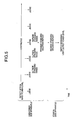
- Fig. 1 shows a block diagram of an optically communicating system in first (and second to fourth) embodiments of the present invention.
- a downward data to a subscriber side apparatus 200 from a station side apparatus 100 is transmitted by using an optical fiber 104 as a medium
- an upward data to the station side apparatus 100 from the subscriber side apparatus 200 is transmitted by using an optical fiber 110 as a medium.
- the downward optical signal including the downward data is passed through the optical fiber 104, it is inputted to the subscriber side apparatus 200. Then, the PD 105 performs the optic-electric conversion on it, and an optical current Ipd after the conversion is inputted to a downward receiving circuit 106.
- the downward receiving circuit 106 converts the optical current Ipd into a digital voltage signal, and further extracts and outputs only the downward data, and also detects a downward input power level, and then converts the detected result into a digital data and outputs.
- the downward receiving circuit 106 has a reception amplifying circuit 1061, a downward pulse train dissolving circuit 1062 and an analog-to-digital converting circuit (ADC) 1063.
- the reception amplifying circuit 1061 converts the optical current Ipd into a digital voltage signal, and the downward pulse train is reproduced.
- the downward pulse train dissolving circuit 1062 extracts and outputs only the downward data from the downward pulse train. Also, the reception amplifying circuit 1061 detects the downward light input power level, and the detected result is converted into a digital data by the ADC 1063 and outputted to an upward transmitting circuit 107.
- the upward optical signal including the upward data transmitted from the subscriber side apparatus 200 is transmitted since the upward transmitting circuit 107 sends a pulse driving current Ild to an LD 108.
- the upward pulse train includes the information with regard to the downward light input power level inputted from the downward receiving circuit 106 and the upward data, and it is generated by an upward pulse train synthesizing circuit 1073.
- An MPD 109 receives a rear light Pb of the LD 108.
- a monitoring current Impd obtained by the optic-electric conversion is inputted to an automatic power control (APC) circuit 1074.
- the APC circuit 1074 adjusts a control voltage of the voltage control current source 1072 so that the monitoring current Impd is constant.
- an upward light output power level Pou is kept substantially constant.
- the upward optical signal including the upward data is passed through the optical fiber 110, it is inputted to the station side apparatus 100. Then, a PD 111 performs the optic-electric conversion on it.
- the optical current Ipd after the conversion is inputted to an upward receiving circuit 112.
- the upward receiving circuit 112 converts the optical current Ipd into a digital voltage signal, and further extracts and outputs the downward data.
- the upward receiving circuit 112 has a reception amplifying circuit 1121 and an upward pulse train dissolving circuit 1122.
- the reception amplifying circuit 1121 converts the optical current Ipd into a digital voltage signal, and the upward pulse train is reproduced.
- the upward pulse train dissolving circuit 1122 extracts and outputs the upward data from the upward pulse train, and also extracts the information with regard to the downward light input power level.
- the downward optical signal including the downward data transmitted from the station side apparatus 100 is transmitted since a downward transmitting circuit 101 sends the pulse driving current Ild to an LD 102.
- the downward pulse train includes the downward data, and it is generated by a downward pulse train synthesizing circuit 1013.
- a control voltage of the voltage control current source 1012 is provided such that on the basis of the information with regard to the downward light input power level inputted from the upward receiving circuit 112, a setting value is determined by a transmission level setting function unit 1015 and converted into a voltage by a digital-to-analog converting circuit (DAC) 1016.
- DAC digital-to-analog converting circuit
- a signal line is connected from the transmission level setting function unit 1015 to the downward pulse train synthesizing circuit 1013. This is required in a fourteenth embodiment of the present invention, which will be described later.
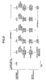
- Fig. 2 is a view explaining the operation of the optically communicating system in the first embodiment of the present invention.
- the upward pulse train synthesizing circuit 1073 collects the detection values of the downward light input power levels for each constant time interval and transmits to the station side apparatus 100.
- the upward pulse train pulse train dissolving circuit 1122 extracts the detection values of the downward light input power levels, and judges whether or not the detection value is within a predetermined range. If the detection value is outside the predetermined range, it reports that fact to the transmission level setting function unit 1015 and switches the downward light output power level.
- the downward light output power level of the station side apparatus 100 is switched on the basis of the downward light input power level information in the input of the subscriber side apparatus 200.
- the optical input power of the subscriber side apparatus 200 can fall in the constant range.
- Fig. 3 is a view explaining the operation of the optically communicating system in the second embodiment of the present invention.
- the upward pulse train synthesizing circuit 1073 collects the detection values of the downward light input power levels for each constant time interval, and judges whether or not the detection value is within the predetermined range. Only if the detection value is outside the predetermined range, it transmits [Standard Violation Report] in an upward direction or a downward direction to the station side apparatus 100.
- the upward pulse train dissolving circuit 1122 extracts [Standard Violation Report]. In the case of the extraction, it further reports that fact to the transmission level setting function unit 1015, and switches the downward light output power level.
- the downward light output power level of the station side apparatus 100 is switched on the basis of the downward light input power level information in the input of the subscriber side apparatus 200.
- the optical input power of the subscriber side apparatus 200 can fall in the constant range.
- the information amount with regard to the light input power level to be transmitted to the station side apparatus 100 is smaller than that of the first embodiment of the present invention. Hence, this has a merit that it is advantageous in the maximum transfer ability of the upward data.
- Fig. 4 is a view explaining the operation of the optically communicating system in the third embodiment of the present invention.
- the third embodiment is the improvement of the optically communicating system in the first embodiment.
- the upward pulse train pulse train dissolving circuit 1122 extracts the detection values of the downward light input power levels, and judges whether or not the detection value is within the predetermined range. If a plurality of judged results are continuously outside the predetermined range, it transmits to the transmission level setting function unit 1015, and switches the downward light output power level.
- the downward light output power level of the station side apparatus 100 is switched on the basis of the downward light input power level information in the input of the subscriber side apparatus 200.
- the optical input power of the subscriber side apparatus 200 can fall in the constant range.
- the downward light output power level is controlled on the basis of the plurality of judged results. Hence, it is possible to avoid the influence caused by the case in which the optical output of the station side apparatus 100 is turned off by any reason.
- Fig. 5 is a view explaining the operation of the optically communicating system in the fourth embodiment of the present invention.
- the fourth embodiment is the improvement of the optically communicating system in the second embodiment.
- the upward pulse train synthesizing circuit 1073 collects the detection values of the downward light input power levels for each constant time interval, and judges whether or not the detection value is within the predetermined range. Only if a plurality of judged results are continuously outside the predetermined range, it transmits [Standard Violation Report] to the station side apparatus 100.
- the downward light output power level of the station side apparatus 100 is switched on the basis of the downward light input power level information in the input of the subscriber side apparatus 200.
- the optical input power of the subscriber side apparatus 200 can fall in the constant range.
- the downward light output power level is controlled on the basis of the plurality of judged results. Hence, it is possible to avoid the influence caused by the case in which the optical output of the station side apparatus 100 is turned off by any reason.
- Fig. 6 shows a block diagram of an optically communicating system in fifth (and sixth) embodiments of the present invention.
- an alarm output is added to the transmission level setting function unit 1015 of the optically communicating system (Fig. 1) in the first to fourth embodiments.
- Fig. 7 is a view explaining the operation of the optically communicating system in the fifth embodiment of the present invention.
- the fifth embodiment is the improvement of the optically communicating system in the first embodiment.
- the station side apparatus 100 when the judged result of the detection value of the downward light input power level received from the subscriber side apparatus 200 becomes outside the predetermined range, even though the downward light output power level is switched, if a next judged result becomes again [Outside Predetermined Range], an alarm is outputted.
- the station side apparatus 100 can judge whether or not the drop in the light input power level in the subscriber side apparatus 200 is caused by any trouble occurring in the downward light transmitting route (the optical fiber 104).
- Fig. 8 is a view explaining the operation of the optically communicating system in the sixth embodiment of the present invention.
- the sixth embodiment is the improvement of the optically communicating system in the second embodiment.
- the subscriber side apparatus 200 when the judged result of the detection value of the downward light input power level becomes [Outside Predetermined Range], even though [Standard Violation Report] is transmitted to the station side apparatus 100, if a next judged result becomes again [Outside Predetermined Range], an alarm is outputted.
- the station side apparatus 100 can judge whether or not the drop in the light input power level in the subscriber side apparatus 200 is caused by any trouble occurring in the downward light transmitting route (the optical fiber 104).
- Fig. 9 shows a block diagram of a part of an optically communicating system in a seventh embodiment of the present invention.
- the seventh embodiment of the present invention is the optically communicating system having the station side apparatus 100 that contains a plurality of subscriber side apparatuses 200 in the optically communicating system in the first to sixth embodiments. That feature lies in the usage of an LD array as a downward transmitting LD.
- Fig. 9 is a peripheral block diagram of the LD array.
- respective optical outputs of the LD array 902 are connected to optical fibers 104a, 104b, 104c and 104d.
- the LD array 902 is connected through wires 906a, 906b, 906c and 906d, and signal transmitting lines 905a, 905b, 905c and 905d to downward transmitting circuits 101a, 101b, 101c and 101d.
- Fig. 18 shows a block diagram showing the periphery of the LD array when the MPD is required.
- the wires 906a, 906b, 906c and 906d are wired while they are jumping over MPDs 1803a, 1803b, 1803c and 1803d, this has the problems that the long wire length brings about the deterioration in the property and that the wiring of the MPDs is very difficult.
- the seventh embodiment of the present invention shown in Fig. 9 does not require the MPD.
- Fig. 10 shows a block diagram of an optically communicating system in an eighth embodiment of the present invention.
- the eighth embodiment of the present invention is designed such that in the optically communicating system in the first to seventh embodiments, the downward optical signal and the upward optical signal are transmitted through a single optical fiber 1004 by using 3dB couplers 1021, 1022.
- the downward optical signal and the upward optical signal are transmitted through the single optical fiber 1004.
- this has the following merits. That is, it is possible to reduce the total cost of the optically communicating system, and it is possible to know that the trouble occurring on the downward light transmitting line is not the trouble on the optical fiber if the alarm output is installed such as the fifth and sixth embodiments of the present invention.
- Fig. 11 shows a block diagram of an optically communicating system in a ninth embodiment of the present invention.
- the ninth embodiment of the present invention is designed such that in the optically communicating system in the first to seventh embodiments, the downward optical signal and the upward optical signal are transmitted through a single optical fiber 1104 by using WDM couplers 1113, 1114.
- the downward optical signal and the upward optical signal are transmitted through the single optical fiber 1104.
- this has the following merits. That is, it is possible to reduce the total cost of the optically communicating system, and it is possible to know that the trouble occurring on the downward light transmitting line is not the trouble on the optical fiber, if the alarm output is installed such as the fifth and sixth embodiments of the present invention.
- the coupler loss is small as compared with the eighth embodiment of the present invention, and it is possible to relax the apparatus specification, such as the decrease in a transmission power, the increase in a reception power and the allowance of an optical fiber transmission loss.
- Fig. 12 shows an optically communicating system in a tenth embodiment of the present invention.
- a downward data to the subscriber side apparatus 200 from the station side apparatus 100 is transmitted by using an optical fiber 1204 as a medium
- an upward data to the station side apparatus 100 from the subscriber side apparatus 200 is transmitted by using an optical fiber 1210 as a medium.
- the upward optical signal including the upward data transmitted from the subscriber side apparatus 200 is transmitted since an upward transmitting circuit 1207 sends a pulse driving current Ild to an LD 1208.
- the upward pulse train includes the upward data, and it is generated by an upward pulse train synthesizing circuit 12073.
- An MPD 1209 receives a rear light Pb of the LD 1208.
- a monitoring current Impd obtained by the optic-electric conversion is inputted to an automatic power control (APC) circuit 12074.
- the APC circuit 12074 adjusts a control voltage of the voltage control current source 12072 so that the monitoring current Impd is constant.
- an upward light output power level Pou is kept substantially constant.
- the upward optical signal including the upward data is passed through the optical fiber 1210, it is inputted to the station side apparatus 100. Then, a PD 1211 performs the optic-electric conversion on it.
- the optical current Ipd after the conversion is inputted to an upward receiving circuit 1212.
- the upward receiving circuit 1212 converts the optical current Ipd into a digital voltage signal, and further extracts and outputs only the upward data, and also detects an upper input power level, and converts the detected result into a digital data and outputs it.
- the upward receiving circuit 1212 has a reception amplifying circuit 12121, an upward pulse train dissolving circuit 12122 and an ADC 12123.
- the reception amplifying circuit 12121 converts the optical current Ipd into a digital voltage signal, and the upward pulse train is reproduced.
- the upward pulse train dissolving circuit 12122 extracts the upward data from the upward pulse train and outputs it. Also, the reception amplifying circuit 12121 detects the upward light input power level, and the detected result is converted into a digital data by the ADC 12123 and outputted.
- the downward optical signal including the downward data transmitted from the station side apparatus 100 is transmitted since a downward transmitting circuit 1201 sends the pulse driving current Ild to an LD 1202.
- the downward pulse train includes the downward data, and it is generated by a downward pulse train synthesizing circuit 12013.
- a control voltage of the voltage control current source 12012 is provided such that on the basis of the upward light input power level information inputted from the upward receiving circuit 1212, the loss of a light transmitting path is estimated by a transmission level setting function unit 12015, and a setting value is determined, and it is converted into a voltage by a DAC 12016.
- the downward optical signal including the downward data is passed through the optical fiber 1204, it is inputted to the subscriber side apparatus 200. Then, a PD 1205 performs the optic-electric conversion on it. An optical current Ipd after the conversion is inputted to a downward receiving circuit 1206.
- the downward receiving circuit 1206 converts the optical current Ipd into a digital voltage signal, and further extracts and outputs only the downward data, and also detects a downward input power level, and then converts the detected result into a digital data and outputs it.
- the downward receiving circuit 1206 has a reception amplifying circuit 12061 and a downward pulse train dissolving circuit 12062.
- the reception amplifying circuit 12061 converts the optical current Ipd into a digital voltage signal, and the downward pulse train is reproduced.
- the downward pulse train dissolving circuit 12062 extracts the downward data from the downward pulse train and outputs it.
- the loss of the light transmitting path is estimated to thereby change the downward light output power level of the station side apparatus 100. Consequently, even if the number of the MPDs in the station side apparatus 100 is reduced, the light input power of the subscriber side apparatus 200 can fall in the constant range.
- a signal line is connected from the transmission level setting function unit 12015 to the downward pulse train synthesizing circuit 12013. This is required in the fourteenth embodiment of the present invention, which will be described later
- the block configuration is similar to that of the tenth embodiment of the present invention, which is shown in Fig. 12.
- the eleventh embodiment of the present invention is designed such that when the downward light output power level is switched in stages on the basis of the upward light input power level, as shown in Fig. 13, a hysteresis property is given to a switching timing.
- the eleventh embodiment of the present invention as mentioned above, even if the upward light input power level is close to the switching timing, it is possible to protect the downward light output power level from being frequently switched.
- the twelfth embodiment of the present invention is designed such that in the optically communicating system of the tenth and eleventh embodiments, the downward optical signal and the upward optical signal are transmitted through a single optical fiber by using a 3dB coupler.
- the downward optical signal and the upward optical signal are transmitted through the single optical fiber.
- this has the merit of protecting the variation in the downward light input power level in the subscriber side apparatus which is caused by the difference between the loss of the upward transmitting path and the loss of the downward transmitting path.
- the thirteenth embodiment of the present invention is designed such that in the optically communicating system of the tenth and eleventh embodiments, the downward optical signal and the upward optical signal are transmitted through a single optical fiber by using a WDM coupler.
- the downward optical signal and the upward optical signal are transmitted through the single optical fiber.
- this has the merit of protecting the variation in the downward light input power level in the subscriber side apparatus which is caused by the difference between the loss of the upward transmitting path and the loss of the downward transmitting path.
- it is possible to relax the apparatus specification, such as the decrease in the transmission power, the increase in the reception power and the allowance of the optical fiber transmission loss.
- the fourteenth embodiment of the present invention is designed as follows. That is, when the downward light output power level is switched in stages, the transmission level setting function unit 12015 switches the downward output power level. Then, at least until the downward receiving circuit of the subscriber side apparatus 200 follows the variation in the downward light input power level, the downward pulse train synthesizing circuit 12013 inserts a dummy data into the downward signal.
- switching the downward output power level can protect the necessary downward data from being erroneous.
- the fifteenth embodiment of the present invention is designed such that the transmission level setting function unit 12015, when changing the downward light output power level in stages, gradually changes the downward output power level and changes it.
- this has the merits that switching the downward output power level can protect the necessary downward data from being erroneous and that the transient reduction in the transmission capacity of the downward data resulting from the switching is never induced.
- the sixteenth embodiment of the present invention is designed such that when the downward optical signal is a burst signal, an optical output is switched between the burst signals, and a preamble signal is added to a lead of the burst signal.
- switching the downward output power level can protect the necessary downward data from being erroneous.
- the station side apparatus can output the alarm to thereby judge the trouble on the downward light transmitting path.
- the station side apparatus can judge the trouble on the downward light transmitting path.
- the optical input power of the subscriber side apparatus can fall in the constant range. Also, it is possible to protect the power level of the downward light output signal to the subscriber side apparatus from being frequently changed.
Landscapes
- Physics & Mathematics (AREA)
- Electromagnetism (AREA)
- Engineering & Computer Science (AREA)
- Computer Networks & Wireless Communication (AREA)
- Signal Processing (AREA)
- Optical Communication System (AREA)
Applications Claiming Priority (2)
| Application Number | Priority Date | Filing Date | Title |
|---|---|---|---|
| JP2002187324 | 2002-06-27 | ||
| JP2002187324A JP2004032476A (ja) | 2002-06-27 | 2002-06-27 | 局側装置及び加入者側装置並びに光通信システム |
Publications (2)
| Publication Number | Publication Date |
|---|---|
| EP1376901A2 true EP1376901A2 (de) | 2004-01-02 |
| EP1376901A3 EP1376901A3 (de) | 2004-03-31 |
Family
ID=29717637
Family Applications (1)
| Application Number | Title | Priority Date | Filing Date |
|---|---|---|---|
| EP03014366A Withdrawn EP1376901A3 (de) | 2002-06-27 | 2003-06-26 | Stationsnahe Einrichtung, teilnehmernahe Einrichtung und optisches Übertragungssystem |
Country Status (4)
| Country | Link |
|---|---|
| US (1) | US20040008990A1 (de) |
| EP (1) | EP1376901A3 (de) |
| JP (1) | JP2004032476A (de) |
| CN (1) | CN1471246A (de) |
Cited By (1)
| Publication number | Priority date | Publication date | Assignee | Title |
|---|---|---|---|---|
| WO2010007525A1 (en) * | 2008-07-14 | 2010-01-21 | Nanotech Semiconductor Ltd. | Method and system for closed loop control of an optical link |
Families Citing this family (11)
| Publication number | Priority date | Publication date | Assignee | Title |
|---|---|---|---|---|
| JP2005045566A (ja) * | 2003-07-23 | 2005-02-17 | Nec Corp | データ通信システム、局側装置、加入者側装置、冗長構成切替判断方法、動作制御方法及びプログラム |
| KR100584383B1 (ko) * | 2004-01-20 | 2006-05-26 | 삼성전자주식회사 | 광선로가입자장치들의 링크 상태를 관리하기 위한광선로종단장치 및 이를 적용한 기가비트 이더넷 기반의수동 광가입자망 |
| JP4699234B2 (ja) * | 2006-02-17 | 2011-06-08 | 三菱電機株式会社 | Ponシステム |
| US8849909B2 (en) * | 2007-07-06 | 2014-09-30 | Yahoo! Inc. | Real-time asynchronous event aggregation systems |
| JP2009033568A (ja) * | 2007-07-27 | 2009-02-12 | Sumitomo Electric Ind Ltd | 光lanシステム |
| US8171388B2 (en) * | 2007-11-15 | 2012-05-01 | Yahoo! Inc. | Trust based moderation |
| JP2010154375A (ja) * | 2008-12-26 | 2010-07-08 | Fujitsu Telecom Networks Ltd | 伝送装置及びその光出力レベル制御方法 |
| JP5094755B2 (ja) * | 2009-01-27 | 2012-12-12 | 三菱電機株式会社 | 光通信装置 |
| US9519682B1 (en) | 2011-05-26 | 2016-12-13 | Yahoo! Inc. | User trustworthiness |
| JP2016208164A (ja) * | 2015-04-20 | 2016-12-08 | ソニー株式会社 | 通信装置、通信システム、および通信方法 |
| JP7520345B2 (ja) | 2020-06-29 | 2024-07-23 | ザインエレクトロニクス株式会社 | 送受信装置、端末装置および送受信システム |
Family Cites Families (13)
| Publication number | Priority date | Publication date | Assignee | Title |
|---|---|---|---|---|
| DE3013533A1 (de) * | 1980-04-08 | 1981-10-15 | Siemens Ag | Schaltungsanordnung mit einer laserdiode zur uebertragung von nachrichtensiglnalen ueber einen lichtwellenleiter |
| US5153754A (en) * | 1989-06-30 | 1992-10-06 | General Electric Company | Multi-layer address lines for amorphous silicon liquid crystal display devices |
| JPH07264131A (ja) * | 1994-03-17 | 1995-10-13 | Fujitsu Ltd | 光加入者伝送システム及びそのシステムに用いられる加入者ユニット |
| JP3132638B2 (ja) * | 1995-08-08 | 2001-02-05 | 日本電気株式会社 | 光波長多重伝送方式 |
| TW312063B (de) * | 1995-08-31 | 1997-08-01 | Sony Co Ltd | |
| JP3455345B2 (ja) * | 1995-10-23 | 2003-10-14 | 富士通株式会社 | 遠隔式光信号制御装置及び遠隔式光信号制御装置の光信号レベル制御方法並びに光信号送信装置及び光信号送信装置における監視信号光レベル制御方法 |
| US6317231B1 (en) * | 1998-09-04 | 2001-11-13 | Lucent Technologies Inc. | Optical monitoring apparatus and method for network provisioning and maintenance |
| JP2000278211A (ja) * | 1999-03-19 | 2000-10-06 | Fujitsu Ltd | 光出力劣化警報機能を有する光出力制御回路 |
| JP3593646B2 (ja) * | 1999-03-19 | 2004-11-24 | 富士通株式会社 | バースト光送信回路 |
| US6654608B1 (en) * | 1999-04-27 | 2003-11-25 | Telefonaktiebolaget Lm Ericsson (Publ) | Tailored power levels at handoff and call setup |
| JP3719119B2 (ja) * | 2000-09-27 | 2005-11-24 | 日本電気株式会社 | 光受信装置 |
| US6928248B2 (en) * | 2001-05-30 | 2005-08-09 | Optical Access, Inc. | Optical communications system with back-up link |
| US7062177B1 (en) * | 2002-06-25 | 2006-06-13 | Cypress Semiconductor Corp. | Out of band communications link for 4-lane optical modules using dark fibers and low-bandwidth LEDs |
-
2002
- 2002-06-27 JP JP2002187324A patent/JP2004032476A/ja active Pending
-
2003
- 2003-06-24 US US10/601,908 patent/US20040008990A1/en not_active Abandoned
- 2003-06-26 EP EP03014366A patent/EP1376901A3/de not_active Withdrawn
- 2003-06-27 CN CNA031480667A patent/CN1471246A/zh active Pending
Cited By (1)
| Publication number | Priority date | Publication date | Assignee | Title |
|---|---|---|---|---|
| WO2010007525A1 (en) * | 2008-07-14 | 2010-01-21 | Nanotech Semiconductor Ltd. | Method and system for closed loop control of an optical link |
Also Published As
| Publication number | Publication date |
|---|---|
| EP1376901A3 (de) | 2004-03-31 |
| US20040008990A1 (en) | 2004-01-15 |
| CN1471246A (zh) | 2004-01-28 |
| JP2004032476A (ja) | 2004-01-29 |
Similar Documents
| Publication | Publication Date | Title |
|---|---|---|
| EP1376901A2 (de) | Stationsnahe Einrichtung, teilnehmernahe Einrichtung und optisches Übertragungssystem | |
| US7326916B2 (en) | Optical submarine transmission system | |
| EP0842575A1 (de) | Verbesserungen an optischen einlieferungs- und abtrennwellenlängenmultiplexsystemen | |
| JP3455345B2 (ja) | 遠隔式光信号制御装置及び遠隔式光信号制御装置の光信号レベル制御方法並びに光信号送信装置及び光信号送信装置における監視信号光レベル制御方法 | |
| WO2004072690A2 (en) | Optical switch having an autorestoration feature for switching from a backup optical path to a primary optical path | |
| AU3577095A (en) | System, method and device for monitoring a fiber optic cable | |
| SE438396B (sv) | Anordning for att detektera avtappning av ljusenergi fran optiska fibrer | |
| US6295147B1 (en) | Wavelength multiplexing transmission apparatus and wavelength demultiplexing reception apparatus | |
| US7016609B2 (en) | Receiver transponder for protected networks | |
| EP1451953B1 (de) | Schnittstelleneinrichtung für ein faseroptisches kommunikationsnetz und verfahren zur verwendung einer solchen einrichtung | |
| US20230291473A1 (en) | Parallel receiver module | |
| US6496288B2 (en) | Wavelength multiplexing transmission apparatus and wavelength demultiplexing reception apparatus | |
| US7460791B2 (en) | Detection of optical light power | |
| JP4840219B2 (ja) | 光受信装置 | |
| EP1486014B1 (de) | Optischer schalter mit optischer versorgung und steuerung | |
| US6469823B2 (en) | Optical wavelength converter and optical wavelength division multiplexing communication system using the same | |
| KR100955427B1 (ko) | 링형 원격 감시 시스템 및 그의 구동 방법 | |
| JP3889735B2 (ja) | 光通信用媒体変換器の電力供給装置及び電力供給方法 | |
| US20110142454A1 (en) | Optical transmission and reception control apparatus | |
| KR102039837B1 (ko) | 광 변환기를 포함하는 부분 방전 센서 및 이를 포함하는 부분 방전 측정 시스템 | |
| NZ235720A (en) | Optical signal repeater uses optical/electrical/optical link | |
| WO2004004135A3 (en) | Bridge terminal output unit | |
| KR101433808B1 (ko) | 양방향 동일 파장을 사용하는 광스위칭 기능 내장형 광통신 단말장비 | |
| KR20040010676A (ko) | 전화선 점유를 검출하기 위한 디바이스 | |
| JPH1065941A (ja) | テレビカメラ用レンズ装置 |
Legal Events
| Date | Code | Title | Description |
|---|---|---|---|
| PUAI | Public reference made under article 153(3) epc to a published international application that has entered the european phase |
Free format text: ORIGINAL CODE: 0009012 |
|
| AK | Designated contracting states |
Kind code of ref document: A2 Designated state(s): AT BE BG CH CY CZ DE DK EE ES FI FR GB GR HU IE IT LI LU MC NL PT RO SE SI SK TR |
|
| AX | Request for extension of the european patent |
Extension state: AL LT LV MK |
|
| PUAL | Search report despatched |
Free format text: ORIGINAL CODE: 0009013 |
|
| AK | Designated contracting states |
Kind code of ref document: A3 Designated state(s): AT BE BG CH CY CZ DE DK EE ES FI FR GB GR HU IE IT LI LU MC NL PT RO SE SI SK TR |
|
| AX | Request for extension of the european patent |
Extension state: AL LT LV MK |
|
| RIC1 | Information provided on ipc code assigned before grant |
Ipc: 7H 04B 10/24 B Ipc: 7H 04B 10/152 B Ipc: 7H 04B 10/207 B Ipc: 7H 04B 10/08 A |
|
| AKX | Designation fees paid |
Designated state(s): DE FR GB |
|
| STAA | Information on the status of an ep patent application or granted ep patent |
Free format text: STATUS: THE APPLICATION IS DEEMED TO BE WITHDRAWN |
|
| 18D | Application deemed to be withdrawn |
Effective date: 20041001 |