EP1376771B1 - Installationssteckvorrichtungen - Google Patents
Installationssteckvorrichtungen Download PDFInfo
- Publication number
- EP1376771B1 EP1376771B1 EP03013289A EP03013289A EP1376771B1 EP 1376771 B1 EP1376771 B1 EP 1376771B1 EP 03013289 A EP03013289 A EP 03013289A EP 03013289 A EP03013289 A EP 03013289A EP 1376771 B1 EP1376771 B1 EP 1376771B1
- Authority
- EP
- European Patent Office
- Prior art keywords
- installation
- plug
- socket
- male
- female
- Prior art date
- Legal status (The legal status is an assumption and is not a legal conclusion. Google has not performed a legal analysis and makes no representation as to the accuracy of the status listed.)
- Expired - Lifetime
Links
- 238000009434 installation Methods 0.000 title claims abstract description 200
- 230000004048 modification Effects 0.000 claims 1
- 238000012986 modification Methods 0.000 claims 1
- 239000000463 material Substances 0.000 description 7
- 125000006850 spacer group Chemical group 0.000 description 3
- 229910001369 Brass Inorganic materials 0.000 description 2
- 239000010951 brass Substances 0.000 description 2
- 239000003086 colorant Substances 0.000 description 2
- 239000004020 conductor Substances 0.000 description 2
- 239000002991 molded plastic Substances 0.000 description 2
- 230000007935 neutral effect Effects 0.000 description 2
- 239000012811 non-conductive material Substances 0.000 description 2
- 238000005452 bending Methods 0.000 description 1
- 238000010276 construction Methods 0.000 description 1
- 238000002788 crimping Methods 0.000 description 1
- 230000000881 depressing effect Effects 0.000 description 1
- 230000000694 effects Effects 0.000 description 1
- 239000002184 metal Substances 0.000 description 1
- 239000004033 plastic Substances 0.000 description 1
- 229920003023 plastic Polymers 0.000 description 1
Images






Classifications
-
- H—ELECTRICITY
- H01—ELECTRIC ELEMENTS
- H01R—ELECTRICALLY-CONDUCTIVE CONNECTIONS; STRUCTURAL ASSOCIATIONS OF A PLURALITY OF MUTUALLY-INSULATED ELECTRICAL CONNECTING ELEMENTS; COUPLING DEVICES; CURRENT COLLECTORS
- H01R31/00—Coupling parts supported only by co-operation with counterpart
- H01R31/02—Intermediate parts for distributing energy to two or more circuits in parallel, e.g. splitter
-
- H—ELECTRICITY
- H01—ELECTRIC ELEMENTS
- H01R—ELECTRICALLY-CONDUCTIVE CONNECTIONS; STRUCTURAL ASSOCIATIONS OF A PLURALITY OF MUTUALLY-INSULATED ELECTRICAL CONNECTING ELEMENTS; COUPLING DEVICES; CURRENT COLLECTORS
- H01R13/00—Details of coupling devices of the kinds covered by groups H01R12/70 or H01R24/00 - H01R33/00
- H01R13/44—Means for preventing access to live contacts
- H01R13/447—Shutter or cover plate
- H01R13/453—Shutter or cover plate opened by engagement of counterpart
- H01R13/4534—Laterally sliding shutter
-
- H—ELECTRICITY
- H01—ELECTRIC ELEMENTS
- H01R—ELECTRICALLY-CONDUCTIVE CONNECTIONS; STRUCTURAL ASSOCIATIONS OF A PLURALITY OF MUTUALLY-INSULATED ELECTRICAL CONNECTING ELEMENTS; COUPLING DEVICES; CURRENT COLLECTORS
- H01R25/00—Coupling parts adapted for simultaneous co-operation with two or more identical counterparts, e.g. for distributing energy to two or more circuits
- H01R25/003—Coupling parts adapted for simultaneous co-operation with two or more identical counterparts, e.g. for distributing energy to two or more circuits the coupling part being secured only to wires or cables
-
- H—ELECTRICITY
- H01—ELECTRIC ELEMENTS
- H01R—ELECTRICALLY-CONDUCTIVE CONNECTIONS; STRUCTURAL ASSOCIATIONS OF A PLURALITY OF MUTUALLY-INSULATED ELECTRICAL CONNECTING ELEMENTS; COUPLING DEVICES; CURRENT COLLECTORS
- H01R13/00—Details of coupling devices of the kinds covered by groups H01R12/70 or H01R24/00 - H01R33/00
- H01R13/62—Means for facilitating engagement or disengagement of coupling parts or for holding them in engagement
- H01R13/627—Snap or like fastening
- H01R13/6271—Latching means integral with the housing
- H01R13/6272—Latching means integral with the housing comprising a single latching arm
Definitions
- THIS INVENTION relates to installation couplers.
- An installation coupler comprises an installation plug which includes plug pins and an installation socket which includes socket contacts for receiving the plug pins.
- the present invention seeks to provide a novel and advantageous installation coupler and a novel and advantageous installation for supplying power.
- Document DE 297 18 572 U discloses an installation corresponding to the preamble of claim 1.
- the invention as claimed relates to an installation for supplying power to a multiplicity of work stations, as claimed.
- an installation coupler for connecting a first cable to a second cable, said first cable having a female installation socket attached thereto and said second cable having a male installation plug attached thereto, said male installation plug comprising a set of male plug pins which include means for enabling the cores of said second cable to be attached thereto and said female installation socket comprising a casing, a set of plug pin contacts, the contacts being in said casing, said contacts including means for attaching the cores of said first cable thereto and having plug pin entrances, a shutter within the casing, said shutter being displaceable between operative and inoperative positions and said shutter extending across said entrances when in an operative position, an opening in the shutter and openings in the walling of the casing for permitting said male plug pins of said male installation plug to pass through said walling and enter the plug pin contacts, said opening in the shutter being partially aligned with one of the openings in the walling whereby an entering
- Said shutter can include a main portion with said opening therein and a flexible arm which extends from said main portion to a mounting, said arm flexing as the shutter moves between said operative and inoperative positions.
- the installation socket has three plug pin contacts arranged in a side-by-side array.
- the shutter can have two or three openings for receiving male plug pins. If the shutter has two openings, then two plug pins pass through these and the third passes alongside an edge of the shutter.
- Said male installation plug and said female installation socket can each comprise an elongate casing having a bore at one end through which the respective cable enters the installation plug or installation socket, said openings being at the other end of the casing of the female installation socket and said plug pins being at the other end of the casing of the male installation plug.
- the male installation plug preferably includes a sleeve which is open at both ends and into one end of which the elongate casing of the male installation plug fits, there being means for interlocking the sleeve and casing, said plug pins protruding from the casing and being within the sleeve.
- Said interlocking means can comprise protrusions and matching recesses for interlocking the sleeve and the casing as the casing is inserted into the sleeve.
- the casing of the female installation socket is configured to fit into said sleeve of the male installation plug whereby the male plug pins in the sleeve encounter said plug pin entrances, there being a releasable latch for securing said installation socket and installation plug to one another.
- the male installation plug and the female installation socket are provided with ribs and grooves, the ribs entering the grooves as the plugs and sockets are joined, and being configured in such manner that each male installation plug can only interlock with a specific female installation socket.
- the female installation socket can include two sets of plug pin contacts for connection to two male installation plugs, the plug pin contacts of one set being electrically connected within the casing to plug pin contacts of the other set, whereby the two sets of sockets can be fed with power from said first cable.
- said female installation socket can comprise first and second elements of electrically conductive metal, each element being configured to provide a first plug pin contact, a second plug pin contact and means for attaching a core of said first cable thereto.
- each strip preferably has a first straight limb with one of said plug pin contacts at one end and means at the other end for connection to the core of said first cable, each element further having a second limb extending transversely from said first straight limb to a third limb which is parallel to said first limb and has a further plug pin contact at an end thereof remote from its connection to said second limb.
- An installation with female installation sockets including one set of plug pin contacts is not part of the claimed invention.
- an installation coupler for connecting a first cable to a second cable
- said installation coupler comprising a female installation socket and a male installation plug
- said male installation plug comprising a set of male plug pins which include means for enabling the cores of said second cable to be attached thereto and said installation socket comprising a casing, a set of plug pin contacts, the contacts being in said casing, said contacts including means for attaching the cores of the first cable thereto and having plug pin entrances, a shutter within the casing, said shutter being displaceable between operative and inoperative positions and said shutter extending across said entrances when in an operative position, an opening in the shutter and openings in the walling of the casing for permitting said male plug pins of said male installation plug to pass through said walling and enter the plug pin contacts, said opening in the shutter being partially aligned with one of the openings in the walling whereby an entering male plug pin displaces the shutter to its inoperative position so that a set of male plug pins can enter the plug pin contacts, said male installation plug
- an installation for supplying power to two work stations comprising a plug for connecting the installation to a source of electrical power, a female installation socket having a casing, a first cable connecting said plug to said female installation socket, first and second male installation plugs each having a set of male plug pins, said female installation socket including two sets of plug pin contacts for receiving said plug pins of said two male installation plugs, the plug pin contacts of one set being electrically connected within the casing to plug pin contacts of the other set whereby the two sets of contacts can be fed with power from said first cable, and second and third cables connected to said male installation plugs, said second and third cables being connected to first and second socket boxes having sockets into which plugs on power utilizing equipment can be plugged.
- a shutter within said casing of the installation socket; said shutter being displaceable between operative and inoperative positions and said shutter extending across said contacts when in an operative position, an opening in the shutter and openings in the casing for permitting said male plug pins of said male installation plugs to pass through and enter said contacts, said opening in the shutter being partially aligned with one of the openings in the casing whereby an entering male plug pin displaces the shutter to its inoperative position so that a set of male plug pins can enter the plug pin contacts.
- an installation for supplying power to a multiplicity of work stations comprising a plug for connecting the installation to a source of electrical power, a series of female installation sockets each having a casing, a first cable connecting said plug to the first of said female installation sockets in the series, a plurality of male installation plugs each having a set of male plug pins, each female installation socket including two sets of plug pin contacts for receiving said plug pins of two of said male installation plugs, the plug pin contacts of one set being electrically connected within the casing of the installation socket to plug pin contacts of the other set, the male installation plugs being connected in pairs to each female installation socket and having second and third cables respective connected thereto, each second cable being connected to the following female installation socket in the series and each third cable being connected to a respective socket box having sockets into which plugs on power utilizing equipment can be plugged.
- each casing there can be a shutter within each casing, said shutters being displaceable between operative and inoperative positions and extending across said contacts when in an operative position, an opening in each shutter and openings in said casings for permitting said male plug pins of said male installation plugs to pass through and enter said contacts, said openings in said shutters being partially aligned with one of said openings in said casing whereby an entering male plug pin displaces the respective shutter to its inoperative position so that a set of male plug pins can enter said contacts.
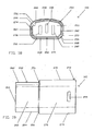
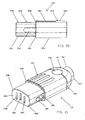
- reference numeral 10 generally designates an installation plug forming one part of an installation coupler.
- the plug 10 comprises a casing 12, three electrical plug pins 18, 20 and 22 and a sleeve 24 (see Figure 8 ).
- the casing 12 and sleeve 24 are manufactured from a nonconductive material, the material preferably being a moulded plastics material.
- the casing 12 comprises two inter-connectable sections, namely, an upper casing part 14 and a lower casing part 16.
- the upper casing part 14 comprises a rear section 26 and an integrally moulded front section 28.
- the front section 28 is essentially rectangular in shape when viewed in plan with a slightly convex top surface 30, rounded side walls 32 and a front wall 33.
- the rear section 26 is generally hemispherical in shape and is integrally moulded with the front section 28. Furthermore, the rear section 26 is stepped with respect to the front section 28 thereby to provide two shoulders 34.
- a semi-cylindrical portion 36 extends rearwardly from the rear section 26.
- a circular protrusion 38 and a rectangular protrusion 40 are provided on the upper casing part 14.
- Recesses 42 are provided on each side of the upper part 14 adjacent the shoulders 34. Holes 44 located in the recesses 42 serve to receive screws (not shown) which connect the upper part 14 and the lower part 16.
- Two longitudinally extending grooves 46 are provided in the inside face of the front section 28.
- An edge of the part 14 is stepped to provide a rim 48 which extends substantially around the perimeter of the upper part 14.
- transverse ribs 47 are provided on the underside of the upper body 14.
- the ribs 47 are each formed with a semi-circular recess 49.
- the lower casing part 16 (see Figures 1 , 4 , 5 and 6 ) comprises a rear section 50 and an integrally moulded front section 52.
- the rear section 50 and front section 52 are substantially identical in shape to the sections 26 and 28 respectively.
- the front section 52 comprises an upstanding front wall 54 and upstanding side walls 56 and 58 ( Figure 1 ).
- the front wall 54 and side walls 56 and 58 are stepped to provide a rim 60 which extends substantially around the perimeter of the lower body 16.
- the rims 48, 60 snap fit together as the casing 12 is assembled.
- a semi-cylindrical portion 62 extends rearwardly from the rear section 50 and is substantially identical in shape to the portion 36. On assembly of the upper casing part 14 to the lower casing part 16, the portions 36 and 62 cooperate to form a cylindrical bore for receiving an electrical cable (not shown).
- Holes 64 are provided in bosses 63 located on each side of the lower part 16 at the region where the rear section 50 and front section 52 join. On assembly of the casing 12, the holes 64 cooperate with the holes 44 to allow screws (not shown), or other suitable attachment means, to be inserted into the holes 44 and 64, thereby securing the upper casing part 14 to the lower casing part 16.
- Walls 66 and separators 68 are moulded integrally with the front wall 54 of the front section 52 to provide recesses 70, 72, 74 for the pins 18, 20, 22.
- a rectangular protrusion 76 (see Figure 6 ) Is provided on the outside of the lower casing part 16.
- the rear section 50 is stepped with respect to the front section 52 to provide shoulders 78.
- Ribs 77 are provided in the lower casing part 16.
- the ribs 77 have semi-circular recesses 79 which cooperate with the recesses 49 in the upper casing part 14 to grip the electrical cable.
- the plug pins 18, 20, 22 each comprise a main portion 81 and an elongate portion 92. Both the main portion 81 and the elongate portion 92 are substantially rectangular in shape and are manufactured from brass, or other suitable electrically conductive material.
- Chamfers 80 are provided between the front edge 82 and the side edges 84 and 86 of the main portion 81. The chamfers 80 assist the pins 18, 20, 22 in cooperating with a shutter, as will be described in more detail hereafter.
- Recesses 88 and 90 are provided in the edges 84 and 86 respectively and assist in locating the pins 18, 20, 22 with respect to the upper and lower casing parts 14 and 16.
- the elongate portion 92 is formed by bending the material through right-angles to form two side walls 94.
- the side walls 94 are perpendicular to the remainder of the elongate portion 92 and form a channel-like configuration which can best be seen in Figure 1 .
- the pins 18, 20, 22 are inserted into the recesses 70, 72, 74 in the lower casing part 16 such that the front wall 54 of the lower casing part 16 is located within the recesses 90 of the pins 18, 20, 22.
- the main portions 81 thus protrude outwardly from the front wall 54.
- the centre earth pin 20 protrudes slightly further than the neutral and live pins 18, 22.
- the elongate portions 92 of the pins 18, 20, 22 are located in the cavity formed by the front wall 54 and the side walls 56 and 58.
- the upper casing part 14 is placed on the lower casing part 16 such that the rim 48 snap fits inside the rim 60 of the lower casing part 14.
- the separators 68 fit into the grooves 46 provided on the inside face of the upper casing part 14.
- the top surfaces of the walls 66 bear on the front wall 33 of the upper casing part 14.
- Screws (not shown), or other suitable attachment means, are then inserted through the holes 44 and 64 to secure the casing parts 14, 16 together.
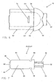
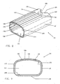
- the sleeve 24 is essentially rectangular in cross-section and comprises a rounded top surface 106, a flat bottom surface 108 and side walls 110 and 112.
- the sleeve 24 is open at each end so that the top surface 106, the bottom surface 108 and side walls 110 and 112 bound a hollow cavity 114 for receiving the casing 12.
- Three shallow grooves 116 extend longitudinally from the front edge 118 of the top surface 106.
- a semi-circular cut-out 120 is provided in the rear edge 122 of the top surface 106. The cut-out 120 is centrally located along the sleeve's longitudinal axis and cooperates with the circular protrusion 38 on the upper casing part 14 on assembly.
- a rectangular recess 105 is provided on the underside of the top surface 106 and receives the protrusion 40 of the upper casing part 14.
- a rectangular opening 124 is provided in the bottom surface 108 which receives the rectangular protrusion 76 provided on the underside of the lower casing part 16.
- An opening 126 (see Figure 11 ) is provided in the side wall 112, the opening 126 being bounded by a straight edge and a generally semi-circular edge.
- Two longitudinally extending ribs 128 are provided in the upper right-hand corner and the lower left-hand corner of the cavity 114, as viewed in Figure 8 , and extend from the front edge 118 of the sleeve 24 to substantially mid-way along the length of the sleeve 24.
- the ends of the ribs 128 remote from the front edge 118 serve as stops.
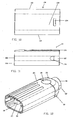
- the assembly of the installation plug 10 is completed by inserting the casing 12 into the cavity 114 of the sleeve 24 (see Figure 12 ) such that the circular protrusion 38 cooperates with the cut-out 120 and such that the rear edge 122 of the sleeve 24 abuts the shoulders 34 and 78.
- the rectangular protrusion 40 located on the top surface 30 of the upper casing part 14 enters the recess 105 in the underside of the top surface 106 of the sleeve 24.
- the rectangular protrusion 76 located on the underside of the lower casing part 16 enters the opening 124 provided in the bottom surface 108 of the sleeve 24.
- reference numeral 130 generally designates an installation socket.
- the installation socket 130 comprises a casing 132, three electrical plug pin contacts 134, 136 and 138, a flexible shutter 140 and a sleeve 142 (see Figure 21 ).
- the casing 132 and sleeve 142 are manufactured from a nonconductive material, the material preferably being a moulded plastic material.
- the casing 132 comprises two inter-connectable sections, referred to hereinafter as an upper casing part 144 and a lower casing part 146.
- the installation socket 130 has many features in common with the installation plug 10 described above. These features will not be described again. In Figures 13 etc they have been designated with the same reference numerals as have been used herein above with the addition of the suffix ".1". Only those features which differentiate the installation socket 130 from the installation plug 10 will be described in detail.
- An elongate protrusion 198 (see particularly Figure 13 ) is integrally moulded to the front section 28.1 of the lower casing part 146.
- the protrusion 198 has a barbed portion 200 at the end of the protrusion 198 remote from the front section 28.1.
- the protrusion 198 is configured so that it can bend slightly.
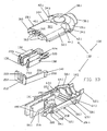
- the flexible shutter 140 comprises a vertical front wall 204 and an elongate flexible vertical side wall 206.
- the front wall 204 and side wall 206 are substantially at right angles to one another and are joined at the right-hand edge of the front wall 204, as viewed in Figure 13 .
- a cylindrical boss 208 is provided at the end of the side wall 206 remote from the front wall 204.
- the shutter is in two parts, the front wall and the side wall being moulded as separate components.
- the front portion of one side face of the wall 206 bears on the right hand end of the shutter 204 as illustrated in Figure 13 .
- Two slots 210 and 212 are provided in the front wall 204.
- the slot 210 is bounded on three sides and open at is upper end (as viewed in Figure 13 ), while the slot 212 is closed on all four sides.
- One vertical edge of the slot 210 is chamfered.
- a rectangular channel 216 extends rearwardly from the front wall 54.1 and merges with a cylindrical recess 218.
- the shutter 140 is assembled to the lower body 146 by inserting the cylindrical boss 208 into the correspondingly shaped recess 218 such that the side wall 206 is within the rectangular channel 216.
- the socket contacts 134, 136, 138 are substantially rectangular in shape and are manufactured from brass, or other suitable electrically conducting material. The material is bent to form two substantially vertical walls 220 and 222 which are joined by a part cylindrical section 224.
- the plug pin contacts 134, 136, 138 also have rearward extensions ( Figure 16 ).
- the side walls 220, 222 and the section 224 form a vertical channel 226 (see Figure 13 ). Each channel 226 is open along one edge, bounded along its other edge by the arcuate section 224 and on the sides by the walls 220, 222.
- Recesses 228 and 230 are provided in the upper and lower edges 232 and 234 respectively of the rearward extension 225 of the side wall 222 and assist in locating and securing the plug pin contacts 134, 136, 138 in the upper and lower casing parts 144 and 146.
- a rectangular elongate portion 236 extends rearwardly from the extension 225 and is bent through right-angles to form two parallel side walls 238.
- the side watts 238 are perpendicular to the remainder of the elongate portion 236.
- the channel-like configuration of the elongate portion 236 can best be seen in Figure 13 .
- Three protrusions 163 protrude forwardly from the front wall 165 of the part 144. There are gaps 166 between the protrusions 163.
- the plug pin contacts 134, 136, 138 are inserted into the slots 191, 192, 193 in the lower casing part 146 such that the front wall 54.1 of the lower casing part 146 is within the recess 230 ( Figure 16 ) of each socket contacts 134, 136, 138. This locates the plug pin contacts 134, 136, 138 with respect to the lower casing part 146. Thereafter, the upper casing part 144 is placed on the lower casing part 146. The spacers 190 fit into grooves (not shown) equivalent to the grooves 46 ( Figure 3 ) which are provided on the underside of the upper casing part 144.
- the sleeve 142 comprises a front section 252 and a rear section 254.
- the sleeve 142 is stepped to provide a shoulder 256 which extends around the circumference of the sleeve 142.
- the sleeve 142 is open at its rear end and its top 268, bottom 270 and side walls 272, 274 bound a cavity for receiving the casing 132.
- the sleeve 142 has a front wall 266 with three vertical slots 278, 280, 282 for receiving the plug pins 18, 20, 22.
- the front section 252 has a side wall 262 which is stepped along its lower edge to provide a longitudinal groove 288 which extends from the front of the section 252 to the shoulder 256.
- the side wall 264 is stepped along its upper edge to provide a longitudinal groove 290 which extends from the front of the section 252 to the shoulder 256.
- the grooves 288, 290 cooperate with the ribs 128 ( Figure 8 ) of the installation plug's sleeve 24.
- a longitudinally extending slot 292 is provided in the side wall 262.
- the slot 292 receives the barbed portion 200 of the elongate protrusion 198 (see Figure 21 ).
- the assembled installation plug 10 is connected to the assembled installation socket 130 by inserting the front section 252 of the sleeve 142 into the cavity 114 ( Figure 9 ) of the sleeve 24 of the installation plug 10 such that the plug pins 18, 20, 22 come into register with the slots 278, 280, 282 provided in the front wall 266 of the sleeve 142.
- the longitudinal ribs 128 in the sleeve 24 enter the longitudinal grooves 288 and 290 of sleeve 142.
- the front wall 204 ( Figure 13 ) of the shutter 140 extends across the front entrances of the plug pin contacts 134, 136, 138 between the wall 266 and the plug pin contacts 134, 136, 138.
- the slots 210 and 212 are slightly out of alignment with the slots 280 and 282.
- the pins 18, 20 and 22 When the installation plug 10 is inserted into the installation socket 130, the pins 18, 20 and 22 enter the slots 282, 280 and 278 respectively. On contact between the earth pin 20 and the chamfer of the slot 210 of the front wall 204 of the shutter 140, the front wall 204 is displaced. This enables the live and neutral pins 18, 22 to enter the respective plug pin contacts 138, 134.
- the installation plug 10 is finally secured to the installation socket 130 when the sleeve 24 abuts the shoulder 256 ( Figure 17 ) of the sleeve 142 and when the barbed portion 200 extends through the slot 126 of the sleeve 24.
- the barbed portion 200 ensures that the installation plug 10 and installation socket 130 cannot be disconnected by merely pulling them apart. Prior to disconnection, the barbed portion 200 must be pressed in using a tool.
- the double installation socket 300 of Figure 24 is used in conjunction with two installation plugs 302 and 304. Where applicable, parts which correspond with parts described above are designated with the same reference numerals with the addition of the suffix .3.
- the cable designated 306 has its three cores attached to three of the socket contact structures 308 illustrated in Figure 26 .
- Each of these structures 308 comprises a crimping section 310 which can be crimped on one of the cores.
- a straight flat bar 312 extends from the section 310 to a plug pin contact 314.
- the plug pin contact 314 is of the same construction as the plug pin contacts 134, 136, 138 shown in Figure 16 .
- a cranked link 318 extends upwardly from the bar 312 to one end of a further straight bar 320 which has a plug pin contact 314 at the other end thereof.
- FIG 27 illustrates a typical power supply installation wherein the three double female installation sockets of Figure 28 are required to connect four socket boxes 322 each having four plug sockets 324 therein.
- the cable 306 is connected to the mains supply via a plug 326.
- a first installation socket 300.1 connects to the upper installation plug 302, which in turn is connected by a power lead 328 to a first socket box 322.1 having four sockets 324.
- the lower installation plug 304 has a power lead 330 connected thereto and this has another double installation socket 300.2 at the other end thereof.
- the arrangement described in relation to the installation socket 300.1 is repeated and thus another socket box 322.2 is supplied with power through a top male installation plug 302 via a power lead 332.
- the lower male installation plug 304 is connected via a power lead 334 to a further double female installation socket 300.3. This arrangement as described is repeated to connect the socket boxes 322.3 and 322.4. Disconnecting any male installation plug 302 does not interrupt the power supply to the downstream part of the circuit illustrated.
- each socket box 322 has two plug sockets 324 then the set of seven double female installation sockets shown in Figure 29 can be used for this purpose.
- a typical power supply installation using this arrangement is illustrated in Figure 30 .
- the third double female installation socket 300.3 in Figure 28 . and the seventh double female installation socket 300.7 of Figure 29 are terminal installation sockets.
- the patterns of grooves 290.1, 290.2 etc. in Figure 28 correspond to the patterns of ribs 128 ( Figure 8 ) of the male installation plugs so that the male installation plugs and female installation sockets can only be connected togther in a predetermined sequence.
- the last pair of installation plugs (referenced 302 and 304 in Figure 27 ) are both connected to socket boxes.
- the socket boxes are designated 322.3 and 322.4.
- One of the last pair of installation plugs is "universal" in that it can be plugged into all of the female installation sockets thereby to enable the series to be terminated at any one of the female installation sockets.
- the male installation plugs and female installation sockets can be numbered and also colour coded.
- the male installation plugs can be moulded in plastics material of different colours.
- the double female installation sockets cannot be moulded in two colours.
- buttons 403 of appropriate colour are pressed into recesses provided therefor in both the upper and lower faces of the double female installation socket.
Landscapes
- Connector Housings Or Holding Contact Members (AREA)
- Paper (AREA)
- Buildings Adapted To Withstand Abnormal External Influences (AREA)
- Diaphragms For Electromechanical Transducers (AREA)
- Insulated Conductors (AREA)
- Details Of Connecting Devices For Male And Female Coupling (AREA)
- Organic Insulating Materials (AREA)
- Unwinding Webs (AREA)
- Supplying Of Containers To The Packaging Station (AREA)
- Laying Of Electric Cables Or Lines Outside (AREA)
- Developing Agents For Electrophotography (AREA)
- Photoreceptors In Electrophotography (AREA)
- Coupling Device And Connection With Printed Circuit (AREA)
- Joints Allowing Movement (AREA)
- Extraction Or Liquid Replacement (AREA)
Claims (4)
- Installation zur Lieferung von Strom an eine Vielzahl von Arbeitsstationen, wobei die Installation einen Stecker (326) zum Anschluss der Installation an eine Stromquelle, eine Reihe von Installations-Anschlussbuchsen (300.1, 300.2, 300.3), ein erstes Kabel (306), welches den Stecker (326) mit der ersten (300.1) der Reihe von Installations-Anschlussbuchsen verbindet, und eine Mehrzahl von Installations-Anschlusssteckern (302, 304) umfasst, von denen jeder einen Satz von Anschlusssteckerstiften (18, 20, 22) aufweist, wobei die Installation dadurch gekennzeichnet ist, dass jede Installations-Anschlussbuchse ein Gehäuse besitzt und zwei Sätze von Installations-Steckerstiftkontakten (134, 136, 138) zum Aufnehmen der Steckerstifte von zwei der Installations-Anschlussstecker enthält, wobei die Steckerstiftkontakte eines Satzes innerhalb des Gehäuses der Installations-Buchse mit den Steckerstiftkontakten des anderen Satzes elektrisch verbunden sind, wobei die Installations-Anschlussstecker (302, 304) paarweise mit jeder Installations-Anschlussbuchse verbunden sind und jeweils daran angeschlossene zweite und dritte Kabel (328, 330, 332, 334) aufweisen, wobei jedes zweite Kabel (330, 334) mit der folgenden Installations-Anschlussbuchse (300.2, 300.3) in der Reihe verbunden ist und jedes dritte Kabel (328, 332) jeweils mit einer Steckdose (322.1, 322.2, 322.3, 322.4) verbunden ist, die Buchsen (324) aufweist, in die Stecker von Geräten eingesteckt werden können, die Strom benötigen, wobei die Instal1ations-Anschlussstecker (302, 304) und die Installations-Anschlussbuchsen mit Rippen (128) und Rillen (290.1, 290.2) ausgestattet sind, wobei die Rippen sich in die Rillen einfügen, wenn die Installations-Stecker und die Installations-Buchsen verbunden werden, und auf eine solche Art konfiguriert sind, dass jeder Installations-Anschlussstecker nur mit einer bestimmten Installations-Anschlussbuchse ineinander greifen kann und dadurch vorbestimmt ist, welcher Installations-Anschlussstecker und welche Installations-Anschlussbuchse jeweils miteinander verbunden werden können.
- Installation nach Anspruch 1, durch die Modifikation gekennzeichnet, dass das zweite und dritte Kabel der Installations-Anschlussstecker, die mit der letzten Installations-Anschlussbuchse der Reihe verbunden sind, beide an Steckdosen angeschlossen sind.
- Installation nach Anspruch 1 oder 2, gekennzeichnet durch eine Klappe (140) innerhalb des Gehäuses jeder Installations-Buchse, wobei die Klappen zwischen Betriebs- und Nichtbetriebs-Positionen verstellbar sind und sich über die Kontakte (134, 136, 138) erstrecken, wenn sie in Betriebs-Position sind, und durch eine Öffnung (212) in jeder Klappe und Öffnungen (278, 280) in den Gehäusen, damit die Steckerstifte (18, 20, 22) der Installations-Anschlussstecker hindurchgehen und in die Kontakte eindringen können, wobei die Öffnungen in den Klappen teilweise mit einer der Öffnungen in dem Gehäuse ausgerichtet sind, wodurch ein eindringender Steckerstift die jeweilige Klappe in ihre Nichtbetriebs-Position verstellt, so dass ein Satz von Anschlusssteckerstiften in die Kontakte eindringen kann.
- Installation nach Anspruch 1, 2 oder 3, dadurch gekennzeichnet, dass die Steckerstiftkontakte eines Satzes über Kontaktstrukturen (308) elektrisch mit den Steckerstiftkontakten des anderen Satzes verbunden sind.
Applications Claiming Priority (2)
| Application Number | Priority Date | Filing Date | Title |
|---|---|---|---|
| GBGB0213705.7A GB0213705D0 (en) | 2002-06-14 | 2002-06-14 | Electrical connectors |
| GB0213705 | 2002-06-14 |
Publications (2)
| Publication Number | Publication Date |
|---|---|
| EP1376771A1 EP1376771A1 (de) | 2004-01-02 |
| EP1376771B1 true EP1376771B1 (de) | 2008-05-21 |
Family
ID=9938595
Family Applications (1)
| Application Number | Title | Priority Date | Filing Date |
|---|---|---|---|
| EP03013289A Expired - Lifetime EP1376771B1 (de) | 2002-06-14 | 2003-06-13 | Installationssteckvorrichtungen |
Country Status (8)
| Country | Link |
|---|---|
| US (1) | US7001222B2 (de) |
| EP (1) | EP1376771B1 (de) |
| AT (1) | ATE396520T1 (de) |
| AU (2) | AU2003204657B8 (de) |
| DE (1) | DE60321091D1 (de) |
| ES (1) | ES2307853T3 (de) |
| GB (2) | GB0213705D0 (de) |
| ZA (1) | ZA200304660B (de) |
Families Citing this family (14)
| Publication number | Priority date | Publication date | Assignee | Title |
|---|---|---|---|---|
| US7145440B2 (en) * | 2004-10-12 | 2006-12-05 | At&T Corp. | Broadband coupler technique for electrical connection to power lines |
| US7063574B2 (en) * | 2004-10-13 | 2006-06-20 | Power Logic Holdings Ag | Installation coupler |
| FR2876775B1 (fr) * | 2004-10-14 | 2006-12-08 | Staubli Faverges Sca | Partie male d'un raccord rapide, ce raccord rapide et jeu de deux tels raccords rapides |
| USD546284S1 (en) * | 2004-10-26 | 2007-07-10 | Logitech Europe S.A. | Connector |
| US20070012372A1 (en) * | 2005-07-01 | 2007-01-18 | Jay Richard M | Cover for fixation pin |
| TWM438590U (en) * | 2012-01-17 | 2012-10-01 | Wang Tung Ling | Flexible pipe structure of lighting string |
| WO2017103728A1 (de) * | 2015-12-14 | 2017-06-22 | A. Steffen AG, Elektrohandel | Mechanische sicherung einer elektrischen steckverbindung für netzspannungen |
| US10038280B2 (en) | 2016-01-29 | 2018-07-31 | International Business Machines Corporation | Cable latch indicator and retainer |
| US10274474B2 (en) * | 2017-06-29 | 2019-04-30 | Honeywell International Inc. | System and method for connecting an external device to a gas detector |
| US11217951B2 (en) * | 2017-09-01 | 2022-01-04 | Delta Electronics, Inc. | AC power adapter and power distribution system employing same |
| EP3849292A1 (de) * | 2017-09-01 | 2021-07-14 | Delta Electronics, Inc. | Wechselstromadapter und stromverteilungssystem mit diesem adapter |
| CN109426326B (zh) * | 2017-09-01 | 2022-03-25 | 台达电子工业股份有限公司 | 多输入电源分配器及其总线组 |
| JP7271498B2 (ja) * | 2020-12-16 | 2023-05-11 | 矢崎総業株式会社 | 機器用コネクタ |
| CN114914739A (zh) * | 2021-02-09 | 2022-08-16 | 哈廷电子有限公司及两合公司 | 用于连接器的嵌件 |
Family Cites Families (44)
| Publication number | Priority date | Publication date | Assignee | Title |
|---|---|---|---|---|
| DE1010602B (de) * | 1955-09-12 | 1957-06-19 | Berker Geb | Elektrische Kupplung |
| US3264599A (en) * | 1961-11-27 | 1966-08-02 | Amp Inc | Connector block assembly |
| US3646499A (en) * | 1970-06-22 | 1972-02-29 | Microdot Inc | Multiple connector |
| US4072382A (en) * | 1976-06-02 | 1978-02-07 | Reschke Kurt W | Safety outlet |
| DE2635721A1 (de) | 1976-08-09 | 1978-02-16 | Bernhard Boekels | Zusatzsicherung an steckdosen insbesondere an intersteckdosen |
| US4399371A (en) * | 1978-07-31 | 1983-08-16 | Dual-Lite, Inc. | Modular wiring systems |
| ATE17416T1 (de) | 1980-12-03 | 1986-01-15 | Wkr Limited | Elektrischer verbindungsstecker. |
| GB2105924B (en) | 1981-08-07 | 1985-01-30 | Conblock Electrical Limited | Electrical connector |
| US4514024A (en) | 1982-09-03 | 1985-04-30 | Automation Industries, Inc. | Shielded electrical connector |
| US4528429A (en) * | 1984-03-02 | 1985-07-09 | Dart Industries Inc. | Electrical switch-plug assembly with baffle |
| DE3414213A1 (de) | 1984-04-14 | 1985-10-24 | E.G.O. Elektro-Geräte Blanc u. Fischer, 7519 Oberderdingen | Grill-steckdose |
| US4704091A (en) * | 1986-06-19 | 1987-11-03 | Owens Rick L | Connector system |
| DE3632676A1 (de) * | 1986-09-26 | 1988-03-31 | Stahl R Schaltgeraete Gmbh | Explosionsgeschuetztes modulgehaeuse |
| US4775327A (en) | 1987-02-17 | 1988-10-04 | Amphenol Corporation | Connector with automatic protection cap |
| JPH0831345B2 (ja) * | 1987-06-11 | 1996-03-27 | マスプロ電工株式会社 | 表示付プラグ |
| DE3743223A1 (de) | 1987-12-19 | 1989-06-29 | Ego Elektro Blanc & Fischer | Geraete-steckdose |
| US5087209A (en) * | 1991-03-08 | 1992-02-11 | Faucher Raymond G | Electrical plug and socket arrangement |
| EP0512208B1 (de) | 1991-05-03 | 1996-01-10 | GIRA GIERSIEPEN GmbH. & CO. KG. | Elektrisches Installationsgerät, insbesondere Schutzkontaktsteckdose mit einer Kinderschutzeinrichtung |
| JP2514466Y2 (ja) | 1991-11-29 | 1996-10-16 | 矢崎総業株式会社 | 端子保護コネクタ |
| US5243136A (en) | 1992-01-07 | 1993-09-07 | King-Cord Co., Ltd. | Electric power cord with double-output terminal |
| US5277620A (en) * | 1992-10-07 | 1994-01-11 | Taylor Terry A | Illuminating receptacle |
| FR2699745B1 (fr) | 1992-12-22 | 1995-02-10 | Roesch Cie Ets Charles | Prise de courant femelle, à protection intégrée. |
| US5449302A (en) * | 1993-08-24 | 1995-09-12 | Cooper Industries, Inc. | Heavy duty electrical connection system |
| US5417585A (en) * | 1994-07-13 | 1995-05-23 | The Whitaker Corporation | Visually keyed connector and plug assemblies |
| US5579201A (en) | 1995-08-23 | 1996-11-26 | Karageozian; Vicken H. | Modified electrical strip for energizing/de-energizing secondary devices simultaneously with a main device |
| JP3135040B2 (ja) * | 1995-11-30 | 2001-02-13 | 矢崎総業株式会社 | 電気自動車の充電用コネクタ |
| US5670847A (en) * | 1996-11-06 | 1997-09-23 | Lin; Chiu-Yuan | Socket structure with slidable insulative disk formed in longitudinal grooves for shock hazard protection |
| DE19742092A1 (de) | 1997-09-24 | 1999-03-25 | Bosch Gmbh Robert | Elektrisch leitendes Kabel |
| DE29718572U1 (de) * | 1997-10-20 | 1997-12-18 | Liao, Pen-Yang, Tainan | Umweltfreundliche, energiesparende Steckdosenleiste |
| TW383910U (en) | 1997-12-17 | 2000-03-01 | Primax Electronics Ltd | Structure of electrode lead plate for double-side & multiple slots socket |
| US6179381B1 (en) * | 1998-01-15 | 2001-01-30 | Krueger International, Inc. | Stationarily-mounted seating structure having electrical and data outlets |
| DE19858011C2 (de) * | 1998-12-16 | 2002-01-24 | Eckhard Halemeier | Steckverbindersystem |
| US6410994B1 (en) | 1999-05-11 | 2002-06-25 | Fellowes Manufacturing Company | Modular power strip |
| US6573617B2 (en) | 1999-05-11 | 2003-06-03 | Fellowes Manufacturing Company | Modular power strip |
| TW417875U (en) * | 1999-05-29 | 2001-01-01 | Ceramate Technical Co Ltd | Safety socket with over heating and over current protection |
| JP2001006812A (ja) * | 1999-06-16 | 2001-01-12 | Yazaki Corp | 半嵌合防止コネクタ |
| US6217353B1 (en) | 1999-12-01 | 2001-04-17 | Aurise Inc. | Structure of a safety receptacle |
| US6383003B1 (en) | 1999-12-01 | 2002-05-07 | Sergio Corona | Environmentally sealed connector system |
| JP2001217049A (ja) | 2000-02-02 | 2001-08-10 | Jst Mfg Co Ltd | 横型モジュラージャック |
| DE10014500C1 (de) | 2000-03-23 | 2001-10-04 | Kid Systeme Gmbh | Schutzsteckdose mit Sicherheitsvorrichtung |
| US6422884B1 (en) * | 2000-06-27 | 2002-07-23 | Sentinel Lighting Wiring Systems, Inc. | Pre-wired circuit component for flexible wiring system |
| US6486407B1 (en) | 2001-06-14 | 2002-11-26 | Trident Design Llc | Power strip with adjustable outlets |
| US6540536B1 (en) | 2001-09-25 | 2003-04-01 | Dekko Engineering, Inc. | Modular electrical system kit with circuit selectors |
| US6537089B1 (en) | 2001-12-14 | 2003-03-25 | Safer Home, Inc. | Gated electrical safety outlet |
-
2002
- 2002-06-14 GB GBGB0213705.7A patent/GB0213705D0/en not_active Ceased
-
2003
- 2003-01-01 ZA ZA200304660A patent/ZA200304660B/xx unknown
- 2003-06-10 US US10/457,775 patent/US7001222B2/en not_active Expired - Fee Related
- 2003-06-11 GB GB0313395A patent/GB2391719B/en not_active Expired - Fee Related
- 2003-06-11 AU AU2003204657A patent/AU2003204657B8/en not_active Ceased
- 2003-06-13 ES ES03013289T patent/ES2307853T3/es not_active Expired - Lifetime
- 2003-06-13 DE DE60321091T patent/DE60321091D1/de not_active Expired - Fee Related
- 2003-06-13 AT AT03013289T patent/ATE396520T1/de not_active IP Right Cessation
- 2003-06-13 EP EP03013289A patent/EP1376771B1/de not_active Expired - Lifetime
-
2009
- 2009-04-14 AU AU2009201437A patent/AU2009201437A1/en not_active Abandoned
Also Published As
| Publication number | Publication date |
|---|---|
| AU2009201437A1 (en) | 2009-05-07 |
| GB0313395D0 (en) | 2003-07-16 |
| EP1376771A1 (de) | 2004-01-02 |
| GB2391719B (en) | 2005-12-28 |
| US20040018775A1 (en) | 2004-01-29 |
| US7001222B2 (en) | 2006-02-21 |
| AU2003204657B8 (en) | 2009-09-03 |
| DE60321091D1 (de) | 2008-07-03 |
| AU2003204657A1 (en) | 2004-01-15 |
| ES2307853T3 (es) | 2008-12-01 |
| ATE396520T1 (de) | 2008-06-15 |
| ZA200304660B (en) | 2004-12-14 |
| AU2003204657B2 (en) | 2009-05-07 |
| GB2391719A (en) | 2004-02-11 |
| GB0213705D0 (en) | 2002-07-24 |
Similar Documents
| Publication | Publication Date | Title |
|---|---|---|
| AU2009201437A1 (en) | Installation couplers | |
| JP3043360B2 (ja) | 符号化手段を具備するコネクタ構造体 | |
| US6146207A (en) | Coupling element for two plugs, adapted male and female elements and coupling device obtained | |
| CZ301312B6 (cs) | Elektrický konektor, rídicí díl, zpusob sestavení elektrického konektoru a nástroj pro toto sestavení | |
| EP0390450A1 (de) | Stapelbarer Zwillingsverbinder für Schnittstellenbus | |
| US8337240B2 (en) | High-current plug-in connector | |
| US5626495A (en) | Screwless connector | |
| GB1575171A (en) | Electrical connector | |
| US4415214A (en) | Electrical plug and socket connectors | |
| AU2007349106B2 (en) | Electric connector with a dust cover | |
| EP0526053B1 (de) | Verbinder | |
| JPS61158679A (ja) | 多極プラグ | |
| KR101046855B1 (ko) | 중계 접속 회로 및 중계 커넥터 | |
| US6247978B1 (en) | Electrical connector with a plurality of unitary conductive clamping elements, each of which has two ends for clamping respectively a conductor of an electrical cable and a terminal pin | |
| US7063574B2 (en) | Installation coupler | |
| US5588876A (en) | Fused electrical connectors | |
| US7267582B2 (en) | Plug-and-socket connection having additional contact device, particularly for data transmission | |
| HRP970280A2 (en) | Electrical connector | |
| KR19990076505A (ko) | 하니스플러그 | |
| ZA200506561B (en) | Installation coupler | |
| US3423722A (en) | Electric connector having interfitting housing members | |
| KR101758674B1 (ko) | 커넥터조립체용 오조립 방지장치 | |
| KR200148910Y1 (ko) | 분지연결편을 갖는 커넥터 | |
| GB2218865A (en) | Plug and socket outlet system | |
| EP0964484A2 (de) | Zweiteiliges Gehäuse des elektrischen Steckers |
Legal Events
| Date | Code | Title | Description |
|---|---|---|---|
| PUAI | Public reference made under article 153(3) epc to a published international application that has entered the european phase |
Free format text: ORIGINAL CODE: 0009012 |
|
| AK | Designated contracting states |
Kind code of ref document: A1 Designated state(s): AT BE BG CH CY CZ DE DK EE ES FI FR GB GR HU IE IT LI LU MC NL PT RO SE SI SK TR |
|
| AX | Request for extension of the european patent |
Extension state: AL LT LV MK |
|
| 17P | Request for examination filed |
Effective date: 20040628 |
|
| 17Q | First examination report despatched |
Effective date: 20040804 |
|
| AKX | Designation fees paid |
Designated state(s): AT BE BG CH CY CZ DE DK EE ES FI FR GR HU IE IT LI LU MC NL PT RO SE SI SK TR |
|
| 17Q | First examination report despatched |
Effective date: 20040804 |
|
| GRAP | Despatch of communication of intention to grant a patent |
Free format text: ORIGINAL CODE: EPIDOSNIGR1 |
|
| GRAS | Grant fee paid |
Free format text: ORIGINAL CODE: EPIDOSNIGR3 |
|
| GRAA | (expected) grant |
Free format text: ORIGINAL CODE: 0009210 |
|
| AK | Designated contracting states |
Kind code of ref document: B1 Designated state(s): AT BE BG CH CY CZ DE DK EE ES FI FR GR HU IE IT LI LU MC NL PT RO SE SI SK TR |
|
| REG | Reference to a national code |
Ref country code: CH Ref legal event code: EP |
|
| REF | Corresponds to: |
Ref document number: 60321091 Country of ref document: DE Date of ref document: 20080703 Kind code of ref document: P |
|
| REG | Reference to a national code |
Ref country code: IE Ref legal event code: FG4D |
|
| PG25 | Lapsed in a contracting state [announced via postgrant information from national office to epo] |
Ref country code: SI Free format text: LAPSE BECAUSE OF FAILURE TO SUBMIT A TRANSLATION OF THE DESCRIPTION OR TO PAY THE FEE WITHIN THE PRESCRIBED TIME-LIMIT Effective date: 20080521 |
|
| PG25 | Lapsed in a contracting state [announced via postgrant information from national office to epo] |
Ref country code: FI Free format text: LAPSE BECAUSE OF FAILURE TO SUBMIT A TRANSLATION OF THE DESCRIPTION OR TO PAY THE FEE WITHIN THE PRESCRIBED TIME-LIMIT Effective date: 20080521 |
|
| PG25 | Lapsed in a contracting state [announced via postgrant information from national office to epo] |
Ref country code: AT Free format text: LAPSE BECAUSE OF FAILURE TO SUBMIT A TRANSLATION OF THE DESCRIPTION OR TO PAY THE FEE WITHIN THE PRESCRIBED TIME-LIMIT Effective date: 20080521 |
|
| REG | Reference to a national code |
Ref country code: ES Ref legal event code: FG2A Ref document number: 2307853 Country of ref document: ES Kind code of ref document: T3 |
|
| PG25 | Lapsed in a contracting state [announced via postgrant information from national office to epo] |
Ref country code: CZ Free format text: LAPSE BECAUSE OF FAILURE TO SUBMIT A TRANSLATION OF THE DESCRIPTION OR TO PAY THE FEE WITHIN THE PRESCRIBED TIME-LIMIT Effective date: 20080521 Ref country code: PT Free format text: LAPSE BECAUSE OF FAILURE TO SUBMIT A TRANSLATION OF THE DESCRIPTION OR TO PAY THE FEE WITHIN THE PRESCRIBED TIME-LIMIT Effective date: 20081021 Ref country code: DK Free format text: LAPSE BECAUSE OF FAILURE TO SUBMIT A TRANSLATION OF THE DESCRIPTION OR TO PAY THE FEE WITHIN THE PRESCRIBED TIME-LIMIT Effective date: 20080521 Ref country code: SE Free format text: LAPSE BECAUSE OF FAILURE TO SUBMIT A TRANSLATION OF THE DESCRIPTION OR TO PAY THE FEE WITHIN THE PRESCRIBED TIME-LIMIT Effective date: 20080821 Ref country code: MC Free format text: LAPSE BECAUSE OF NON-PAYMENT OF DUE FEES Effective date: 20080630 |
|
| PG25 | Lapsed in a contracting state [announced via postgrant information from national office to epo] |
Ref country code: SK Free format text: LAPSE BECAUSE OF FAILURE TO SUBMIT A TRANSLATION OF THE DESCRIPTION OR TO PAY THE FEE WITHIN THE PRESCRIBED TIME-LIMIT Effective date: 20080521 Ref country code: RO Free format text: LAPSE BECAUSE OF FAILURE TO SUBMIT A TRANSLATION OF THE DESCRIPTION OR TO PAY THE FEE WITHIN THE PRESCRIBED TIME-LIMIT Effective date: 20080521 Ref country code: BE Free format text: LAPSE BECAUSE OF FAILURE TO SUBMIT A TRANSLATION OF THE DESCRIPTION OR TO PAY THE FEE WITHIN THE PRESCRIBED TIME-LIMIT Effective date: 20080521 |
|
| PLBE | No opposition filed within time limit |
Free format text: ORIGINAL CODE: 0009261 |
|
| STAA | Information on the status of an ep patent application or granted ep patent |
Free format text: STATUS: NO OPPOSITION FILED WITHIN TIME LIMIT |
|
| REG | Reference to a national code |
Ref country code: IE Ref legal event code: MM4A |
|
| 26N | No opposition filed |
Effective date: 20090224 |
|
| PG25 | Lapsed in a contracting state [announced via postgrant information from national office to epo] |
Ref country code: BG Free format text: LAPSE BECAUSE OF FAILURE TO SUBMIT A TRANSLATION OF THE DESCRIPTION OR TO PAY THE FEE WITHIN THE PRESCRIBED TIME-LIMIT Effective date: 20080821 Ref country code: EE Free format text: LAPSE BECAUSE OF FAILURE TO SUBMIT A TRANSLATION OF THE DESCRIPTION OR TO PAY THE FEE WITHIN THE PRESCRIBED TIME-LIMIT Effective date: 20080521 Ref country code: IE Free format text: LAPSE BECAUSE OF NON-PAYMENT OF DUE FEES Effective date: 20080613 |
|
| PGFP | Annual fee paid to national office [announced via postgrant information from national office to epo] |
Ref country code: NL Payment date: 20090623 Year of fee payment: 7 |
|
| PGFP | Annual fee paid to national office [announced via postgrant information from national office to epo] |
Ref country code: IT Payment date: 20090615 Year of fee payment: 7 |
|
| REG | Reference to a national code |
Ref country code: FR Ref legal event code: ST Effective date: 20090731 |
|
| PGFP | Annual fee paid to national office [announced via postgrant information from national office to epo] |
Ref country code: ES Payment date: 20090630 Year of fee payment: 7 Ref country code: FR Payment date: 20090629 Year of fee payment: 7 |
|
| PGFP | Annual fee paid to national office [announced via postgrant information from national office to epo] |
Ref country code: DE Payment date: 20090618 Year of fee payment: 7 |
|
| REG | Reference to a national code |
Ref country code: FR Ref legal event code: D3 |
|
| PG25 | Lapsed in a contracting state [announced via postgrant information from national office to epo] |
Ref country code: CY Free format text: LAPSE BECAUSE OF FAILURE TO SUBMIT A TRANSLATION OF THE DESCRIPTION OR TO PAY THE FEE WITHIN THE PRESCRIBED TIME-LIMIT Effective date: 20080521 Ref country code: LU Free format text: LAPSE BECAUSE OF NON-PAYMENT OF DUE FEES Effective date: 20080613 Ref country code: HU Free format text: LAPSE BECAUSE OF FAILURE TO SUBMIT A TRANSLATION OF THE DESCRIPTION OR TO PAY THE FEE WITHIN THE PRESCRIBED TIME-LIMIT Effective date: 20081122 |
|
| PG25 | Lapsed in a contracting state [announced via postgrant information from national office to epo] |
Ref country code: TR Free format text: LAPSE BECAUSE OF FAILURE TO SUBMIT A TRANSLATION OF THE DESCRIPTION OR TO PAY THE FEE WITHIN THE PRESCRIBED TIME-LIMIT Effective date: 20080521 |
|
| PG25 | Lapsed in a contracting state [announced via postgrant information from national office to epo] |
Ref country code: GR Free format text: LAPSE BECAUSE OF FAILURE TO SUBMIT A TRANSLATION OF THE DESCRIPTION OR TO PAY THE FEE WITHIN THE PRESCRIBED TIME-LIMIT Effective date: 20080822 |
|
| PGFP | Annual fee paid to national office [announced via postgrant information from national office to epo] |
Ref country code: CH Payment date: 20100520 Year of fee payment: 8 |
|
| REG | Reference to a national code |
Ref country code: NL Ref legal event code: V1 Effective date: 20110101 |
|
| REG | Reference to a national code |
Ref country code: FR Ref legal event code: ST Effective date: 20110228 |
|
| PG25 | Lapsed in a contracting state [announced via postgrant information from national office to epo] |
Ref country code: IT Free format text: LAPSE BECAUSE OF NON-PAYMENT OF DUE FEES Effective date: 20100613 |
|
| PG25 | Lapsed in a contracting state [announced via postgrant information from national office to epo] |
Ref country code: DE Free format text: LAPSE BECAUSE OF NON-PAYMENT OF DUE FEES Effective date: 20110101 |
|
| PG25 | Lapsed in a contracting state [announced via postgrant information from national office to epo] |
Ref country code: NL Free format text: LAPSE BECAUSE OF NON-PAYMENT OF DUE FEES Effective date: 20110101 Ref country code: FR Free format text: LAPSE BECAUSE OF NON-PAYMENT OF DUE FEES Effective date: 20100630 |
|
| REG | Reference to a national code |
Ref country code: ES Ref legal event code: FD2A Effective date: 20111118 |
|
| PG25 | Lapsed in a contracting state [announced via postgrant information from national office to epo] |
Ref country code: ES Free format text: LAPSE BECAUSE OF NON-PAYMENT OF DUE FEES Effective date: 20100614 |
|
| REG | Reference to a national code |
Ref country code: CH Ref legal event code: PL |
|
| PG25 | Lapsed in a contracting state [announced via postgrant information from national office to epo] |
Ref country code: LI Free format text: LAPSE BECAUSE OF NON-PAYMENT OF DUE FEES Effective date: 20110630 Ref country code: CH Free format text: LAPSE BECAUSE OF NON-PAYMENT OF DUE FEES Effective date: 20110630 |