EP1375711A2 - Garnabzugsdüse für eine Offenend-Spinnvorrichtung - Google Patents
Garnabzugsdüse für eine Offenend-Spinnvorrichtung Download PDFInfo
- Publication number
- EP1375711A2 EP1375711A2 EP03009160A EP03009160A EP1375711A2 EP 1375711 A2 EP1375711 A2 EP 1375711A2 EP 03009160 A EP03009160 A EP 03009160A EP 03009160 A EP03009160 A EP 03009160A EP 1375711 A2 EP1375711 A2 EP 1375711A2
- Authority
- EP
- European Patent Office
- Prior art keywords
- yarn
- yarn take
- nozzle
- take
- bumps
- Prior art date
- Legal status (The legal status is an assumption and is not a legal conclusion. Google has not performed a legal analysis and makes no representation as to the accuracy of the status listed.)
- Granted
Links
Images


Classifications
-
- D—TEXTILES; PAPER
- D01—NATURAL OR MAN-MADE THREADS OR FIBRES; SPINNING
- D01H—SPINNING OR TWISTING
- D01H4/00—Open-end spinning machines or arrangements for imparting twist to independently moving fibres separated from slivers; Piecing arrangements therefor; Covering endless core threads with fibres by open-end spinning techniques
- D01H4/40—Removing running yarn from the yarn forming region, e.g. using tubes
Definitions
- the invention relates to a yarn take-off nozzle for open-end spinning devices, with a pulling yarn deflecting arched contact surface, which is essentially a flat end face in an essentially perpendicular yarn take-off channel passes over, and with linear unevenness arranged in the contact surface, which on cross the entire length of the yarn to be drawn off at an acute crossing angle, the deviates significantly from 0 ° and 90 °.
- Bumps of this type on yarn take-off nozzles are known and can either be notches or be formed as bump-like projections. Such are commonly used in practice Bumps are either radial to the center of the yarn take-off nozzle or spiral to.
- the US Patent 3,965,661 for radial bumps and DE 37 07 526 A1 for called spiral bumps It is also known (German interpretation 21 40 157), on the same yarn take-off nozzle both radial and concentric to the center Provide arranged bumps in the form of notches.
- Yarn take-off nozzles guide the spun yarn from the heart of the open-end spinning device, the so-called spinning rotor, to the outside.
- the formation of the yarn take-off nozzle itself has one great influence on the quality of the spun yarn and on the spinning stability of the open-end spinning device.
- the design of the yarn take-off nozzle ultimately determines the Spinning conditions in the spinning rotor. This is especially true with regard to the yarn twist made by the spun yarn runs back into the inside of a fiber collecting groove of the spinning rotor.
- the Applying bumps in the form of notches or projections has proven to be suitable here Compromise solution proven.
- the drawn yarn is given a so-called False twist, which increases the spinning stability and is periodically interrupted by he "jumps back" from time to time. Unfortunately, it has been shown that a Increasing the spinning stability often with a deterioration in the quality of the spun yarns accompanied.
- the invention is based on the object, one of the unevenness mentioned to have featured yarn take-off nozzle that as well in terms of spinning stability as well has good properties in terms of yarn quality.
- the task is solved in that neighboring bumps are so close together are arranged so that the yarn always contacts at least one unevenness.
- a yarn draw-off nozzle with a contact surface is created, in which the false twist effect increases to increase the spinning stability without Fiber damage occurs as with the notched ones known in practice
- Yarn take-off nozzles are known. Due to the features of the invention, the yarn is on the The edges of the bumps are continuously unrolled. The course of the bumps according to The invention guarantees that - in the presence of bumps formed as notches - the yarn is not pulled into the notch base, but on the notch edges at the bottom the radius of the contact surface undergoes a certain wrap, which the false twist effect of the yarn take-off nozzle without damaging the fibers.
- the bumps mentioned should be arranged so that the crossing angle with the yarn to be drawn is always between 15 ° and 45 °. It is particularly advantageous if the crossing angle is at least approximately constant over the entire length of the bumps is. For the bumps designed according to the invention, this requires a slight one curved curve, but on the other hand leads to a particularly continuous Force application.
- the unevenness can either in the direction of the yarn or point in the opposite direction.
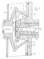
- the rotor plate 2 has a fiber sliding surface which widens conically to form a fiber collecting groove 6 7 on.
- the hollow interior of the rotor plate 2 has its largest Diameter.
- the spinning rotor 1 can be opened through a front opening 8 in the rotor housing 5 Pull out the operating side.
- the opening 8 of the rotor housing 5 is together with the open front 9 of the rotor plate 2 by a cover 10 which can be moved away locked.
- the cover 10 then puts on with the interposition of an annular seal 11 the rotor housing 5.
- the cover 10 contains a fiber feed channel 12 which lies outside the drawing plane and which in a manner not shown, because in a known manner, begins at an opening roller and its mouth 13 is directed against the fiber sliding surface 7. Due to the effect of the mentioned vacuum source During operation, the fibers are separated by the opening roller through the fiber feed channel 12 shot against the fiber sliding surface 7, from where they slide into the fiber collecting groove 6, there one Form fiber ring and in a known manner as yarn 14 in the axial direction of the shaft 3 subtracted from. The transport air sucked in via the fiber feed channel 12 can be supplied via a Drain overflow gap 15 on the open front side 9 of the spinning rotor 1.
- the spun yarn 14 shown in dash-dot lines is first of all from the fiber collecting groove 6 at least approximately in a normal plane of the spinning rotor 1 and then via a yarn take-off channel 17 of a yarn take-off nozzle 18 according to FIG Deduction direction A is drawn off by means of a pair of draw rollers, not shown, and one also supplied winding package, not shown.
- the Garnabzugskanal 17 is coaxial with Shaft 3 of the spinning rotor 1, so that the yarn 14 by means of the yarn take-off nozzle 18 by approximately 90 ° is deflected, the yarn 14 in the normal plane mentioned corresponding to the Direction of rotation B revolves like a crank, see also FIG. 2.
- the yarn take-off nozzle 18 is by means of a External thread 20 screwed into a corresponding hole in the cover 10.
- a funnel-shaped arched contact surface 21 which on a lying in the normal plane, in Essentially flat end face 19 begins.
- the Contact surface 21 is an arcuate curved surface, which is directly the smallest cross section 22 of the yarn take-off channel 17 follows. In the illustrated axial section in FIG about a quarter circle with a radius of curvature that is, for example, 3 mm.
- the contact surface 21 is provided with linear unevenness 23, 3 as notches 24 or according to FIG. 4 as bump-like projections can.
- the invention relates specifically to the design of these bumps 23 with the The aim is to produce a good quality yarn 14 with high spinning stability of the open-end spinning device produce.
- the linear unevenness 23 cross on it entire length of the yarn 14 to be drawn off at an acute crossing angle ⁇ , which is clear deviates from both 0 ° and 90 °.
- adjacent bumps 23 are like this arranged close together that the yarn 14 always at least one bump 23, however preferably contacted several bumps 23 at the same time. This will in particular achieved that the withdrawn yarn 14 with the participation of the radius of the contact surface 21 to the Edges of the bumps 23 undergoes a certain wrap without, for example, in the Notch ground to be drawn into.
- the crossing angle ⁇ is advantageously between 15 ° and 45 °.
- the bumps 23, starting from the area of the yarn take-off channel 17, show the variant shown in Figure 2 in the direction of rotation B of the yarn 14th
- the bumps 23 are formed as slightly curved curves, what leads to the fact that the crossing angle ⁇ remains constant at every point of an unevenness 23. In FIG. 5 shows a large number of such crossing angles ⁇ . It can also be seen that Adjacent bumps 23 are so close together that the yarn 14 is always contacted several bumps 23.
Landscapes
- Engineering & Computer Science (AREA)
- Mechanical Engineering (AREA)
- Textile Engineering (AREA)
- Spinning Or Twisting Of Yarns (AREA)
- Spinning Methods And Devices For Manufacturing Artificial Fibers (AREA)
Abstract
Description
Claims (5)
- Garnabzugsdüse für Offenend-Spinnvorrichtungen, mit einer ein abzuziehendes Garn umlenkenden gewölbten Kontaktfläche, die von einer im Wesentlichen ebenen Stirnfläche in einen im Wesentlichen senkrecht dazu verlaufenden Garnabzugskanal übergeht, und mit in der Kontaktfläche angeordneten linienförmigen Unebenheiten, welche auf ihrer gesamten Länge das abzuziehende Garn unter einem spitzen Kreuzungswinkel kreuzen, der deutlich von 0° und 90° abweicht, dadurch gekennzeichnet, dass benachbarte Unebenheiten (23) so dicht beieinander angeordnet sind, dass das Garn (14) stets mindestens eine Unebenheit (23) kontaktiert.
- Garnabzugsdüse nach Anspruch 1, dadurch gekennzeichnet, dass der Kreuzungswinkel (α) zwischen 15° und 45° beträgt.
- Garnabzugdüse nach Anspruch 1 oder 2, dadurch gekennzeichnet, dass der Kreuzungswinkel (α) über die gesamte Länge der Unebenheiten (23) wenigstens annähernd konstant ist.
- Garnabzugsdüse nach einem der Ansprüche 1 bis 3, dadurch gekennzeichnet, dass die Unebenheiten (23), ausgehend vom Bereich des Garnabzugskanals (17), in Umlaufrichtung (B) des Garnes (14) weisen.
- Garnabzugsdüse nach einem der Ansprüche 1 bis 3. dadurch gekennzeichnet, dass die Unebenheiten (23), ausgehend vom Bereich des Garnabzugskanals (17), entgegen der Umlaufrichtung (B) des Garnes (14) weisen.
Applications Claiming Priority (2)
| Application Number | Priority Date | Filing Date | Title |
|---|---|---|---|
| DE10228504 | 2002-06-20 | ||
| DE10228504A DE10228504A1 (de) | 2002-06-20 | 2002-06-20 | Garnabzugsdüse für Offenend-Spinnvorrichtungen |
Publications (3)
| Publication Number | Publication Date |
|---|---|
| EP1375711A2 true EP1375711A2 (de) | 2004-01-02 |
| EP1375711A3 EP1375711A3 (de) | 2004-05-12 |
| EP1375711B1 EP1375711B1 (de) | 2010-01-20 |
Family
ID=29716664
Family Applications (1)
| Application Number | Title | Priority Date | Filing Date |
|---|---|---|---|
| EP03009160A Expired - Lifetime EP1375711B1 (de) | 2002-06-20 | 2003-04-19 | Garnabzugsdüse für eine Offenend-Spinnvorrichtung |
Country Status (4)
| Country | Link |
|---|---|
| EP (1) | EP1375711B1 (de) |
| CN (1) | CN1470691A (de) |
| AT (1) | ATE455883T1 (de) |
| DE (1) | DE10228504A1 (de) |
Families Citing this family (7)
| Publication number | Priority date | Publication date | Assignee | Title |
|---|---|---|---|---|
| DE102004013828B4 (de) * | 2004-03-15 | 2007-03-15 | Wilhelm Stahlecker Gmbh | Garnabzugsdüse für eine Offenend-Rotorspinnvorrichtung |
| DE102004036953B4 (de) * | 2004-07-21 | 2012-11-08 | Wilhelm Stahlecker Gmbh | Garnabzugsdüse für eine Offenend-Rotorspinnvorrichtung |
| DE102011120106A1 (de) * | 2011-12-02 | 2013-06-06 | Oerlikon Textile Gmbh & Co. Kg | Deckelelement einer Offenend-Spinnvorrichtung zum Verschließen eines besaugten, nach vorne hin offenen Rotorgehäuses |
| DE102012108550A1 (de) * | 2012-02-08 | 2013-08-08 | Maschinenfabrik Rieter Ag | Garnabzugseinheit einer Rotorspinnmaschine sowie Verfahren zur Herstellung eines Garns mit Hilfe einer Rotorspinnmaschine |
| CN102747470B (zh) * | 2012-07-12 | 2015-07-08 | 宁波双盾纺织帆布实业有限公司 | 阻捻头 |
| CN106319697A (zh) * | 2016-11-15 | 2017-01-11 | 江苏普美纺织有限公司 | 一种转杯纺假捻盘 |
| CN106319696A (zh) * | 2016-11-15 | 2017-01-11 | 江苏普美纺织有限公司 | 一种转杯纺假捻盘 |
Family Cites Families (4)
| Publication number | Priority date | Publication date | Assignee | Title |
|---|---|---|---|---|
| DE1560302C3 (de) * | 1966-08-24 | 1981-11-26 | Schubert & Salzer Maschinenfabrik Ag, 8070 Ingolstadt | Offen-End-Spinnvorrichtung |
| DE3707526A1 (de) * | 1987-03-09 | 1988-09-29 | Vnii Legkogo Textil Masch | Einrichtung zum ringlosen spinnen |
| DE4224632B4 (de) * | 1992-07-25 | 2004-05-27 | Saurer Gmbh & Co. Kg | Vorrichtung zum Offenend-Spinnen |
| DE19738382B4 (de) * | 1997-09-03 | 2006-03-09 | Saurer Gmbh & Co. Kg | Fadenabzugsdüse |
-
2002
- 2002-06-20 DE DE10228504A patent/DE10228504A1/de not_active Ceased
-
2003
- 2003-04-19 EP EP03009160A patent/EP1375711B1/de not_active Expired - Lifetime
- 2003-04-19 AT AT03009160T patent/ATE455883T1/de active
- 2003-06-20 CN CNA031486029A patent/CN1470691A/zh active Pending
Also Published As
| Publication number | Publication date |
|---|---|
| ATE455883T1 (de) | 2010-02-15 |
| DE10228504A1 (de) | 2004-01-08 |
| EP1375711A3 (de) | 2004-05-12 |
| CN1470691A (zh) | 2004-01-28 |
| EP1375711B1 (de) | 2010-01-20 |
Similar Documents
| Publication | Publication Date | Title |
|---|---|---|
| DE19738382B4 (de) | Fadenabzugsdüse | |
| DE4224632B4 (de) | Vorrichtung zum Offenend-Spinnen | |
| WO2006027216A1 (de) | Luftdüsenspinnvorrichtung | |
| EP1375711B1 (de) | Garnabzugsdüse für eine Offenend-Spinnvorrichtung | |
| DE19610960A1 (de) | Verfahren zum Offenend-Spinnen | |
| DE1760598C3 (de) | Offen-End-Spinnvorrichtung | |
| DE3320768A1 (de) | Vorrichtung zum oe-friktionsspinnen | |
| AT501520B1 (de) | Garnabzugseinrichtung für offenend-spinnvorrichtungen | |
| CH674746A5 (de) | ||
| DE3318924A1 (de) | Vorrichtung zum oe-friktionsspinnen | |
| DE10318305A1 (de) | Garnabzugsdüse für Offenend-Spinnvorrichtungen | |
| EP0227688B1 (de) | Offenend-spinnvorrichtung | |
| DE10101660A1 (de) | Spinnvorrichtung | |
| AT500772B1 (de) | Garnabzugsdüse für eine offenend-rotorspinnvorrichtung | |
| DE19901147B4 (de) | Garnabzugsdüse für eine Offenend-Rotorspinnvorrichtung | |
| CH636384A5 (en) | Open-end spinning apparatus | |
| EP1445358B1 (de) | Garnabzugsdüse für Offenend-Rotorspinnvorrichtungen | |
| DE10305794B4 (de) | Garnabzugsdüse für Offenend-Rotorspinnvorrichtungen | |
| DE3942454A1 (de) | Verfahren und einrichtung zum herstellen eines spinnfasergarns | |
| AT505070B1 (de) | Garnabzugsdüse für eine offenend-rotorspinnvorrichtung | |
| DE10106771A1 (de) | Spinnmaschine mit einer Vielzahl von Spinnstellen | |
| AT388185B (de) | Vorrichtung zum herstellen eines garnes | |
| DE19608830A1 (de) | Vorrichtung zum Zuführen und Auflösen von bandförmigem Fasermaterial zu Einzelfasern | |
| AT388182B (de) | Vorrichtung zum herstellen eines garnes | |
| DE4223833A1 (de) | Verfahren und Vorrichtung zum Spinnen eines Garnes nach einem Friktionsspinnverfahren |
Legal Events
| Date | Code | Title | Description |
|---|---|---|---|
| PUAI | Public reference made under article 153(3) epc to a published international application that has entered the european phase |
Free format text: ORIGINAL CODE: 0009012 |
|
| AK | Designated contracting states |
Kind code of ref document: A2 Designated state(s): AT BE BG CH CY CZ DE DK EE ES FI FR GB GR HU IE IT LI LU MC NL PT RO SE SI SK TR |
|
| AX | Request for extension of the european patent |
Extension state: AL LT LV MK |
|
| PUAL | Search report despatched |
Free format text: ORIGINAL CODE: 0009013 |
|
| AK | Designated contracting states |
Kind code of ref document: A3 Designated state(s): AT BE BG CH CY CZ DE DK EE ES FI FR GB GR HU IE IT LI LU MC NL PT RO SE SI SK TR |
|
| AX | Request for extension of the european patent |
Extension state: AL LT LV MK |
|
| 17P | Request for examination filed |
Effective date: 20040615 |
|
| AKX | Designation fees paid |
Designated state(s): AT CH CZ IT LI |
|
| REG | Reference to a national code |
Ref country code: DE Ref legal event code: 8566 |
|
| 17Q | First examination report despatched |
Effective date: 20061109 |
|
| GRAP | Despatch of communication of intention to grant a patent |
Free format text: ORIGINAL CODE: EPIDOSNIGR1 |
|
| GRAS | Grant fee paid |
Free format text: ORIGINAL CODE: EPIDOSNIGR3 |
|
| GRAA | (expected) grant |
Free format text: ORIGINAL CODE: 0009210 |
|
| AK | Designated contracting states |
Kind code of ref document: B1 Designated state(s): AT CH CZ IT LI |
|
| REG | Reference to a national code |
Ref country code: CH Ref legal event code: EP |
|
| PLBE | No opposition filed within time limit |
Free format text: ORIGINAL CODE: 0009261 |
|
| STAA | Information on the status of an ep patent application or granted ep patent |
Free format text: STATUS: NO OPPOSITION FILED WITHIN TIME LIMIT |
|
| PG25 | Lapsed in a contracting state [announced via postgrant information from national office to epo] |
Ref country code: CZ Free format text: LAPSE BECAUSE OF FAILURE TO SUBMIT A TRANSLATION OF THE DESCRIPTION OR TO PAY THE FEE WITHIN THE PRESCRIBED TIME-LIMIT Effective date: 20100120 |
|
| REG | Reference to a national code |
Ref country code: CH Ref legal event code: PL |
|
| 26N | No opposition filed |
Effective date: 20101021 |
|
| PG25 | Lapsed in a contracting state [announced via postgrant information from national office to epo] |
Ref country code: CH Free format text: LAPSE BECAUSE OF NON-PAYMENT OF DUE FEES Effective date: 20100430 Ref country code: LI Free format text: LAPSE BECAUSE OF NON-PAYMENT OF DUE FEES Effective date: 20100430 |
|
| PG25 | Lapsed in a contracting state [announced via postgrant information from national office to epo] |
Ref country code: IT Free format text: LAPSE BECAUSE OF FAILURE TO SUBMIT A TRANSLATION OF THE DESCRIPTION OR TO PAY THE FEE WITHIN THE PRESCRIBED TIME-LIMIT Effective date: 20100120 |
|
| PGFP | Annual fee paid to national office [announced via postgrant information from national office to epo] |
Ref country code: AT Payment date: 20110418 Year of fee payment: 9 |
|
| REG | Reference to a national code |
Ref country code: AT Ref legal event code: MM01 Ref document number: 455883 Country of ref document: AT Kind code of ref document: T Effective date: 20120419 |
|
| PG25 | Lapsed in a contracting state [announced via postgrant information from national office to epo] |
Ref country code: AT Free format text: LAPSE BECAUSE OF NON-PAYMENT OF DUE FEES Effective date: 20120419 |