EP1372546B1 - Fussprothese mit einstellbarer leistung - Google Patents
Fussprothese mit einstellbarer leistung Download PDFInfo
- Publication number
- EP1372546B1 EP1372546B1 EP02733905A EP02733905A EP1372546B1 EP 1372546 B1 EP1372546 B1 EP 1372546B1 EP 02733905 A EP02733905 A EP 02733905A EP 02733905 A EP02733905 A EP 02733905A EP 1372546 B1 EP1372546 B1 EP 1372546B1
- Authority
- EP
- European Patent Office
- Prior art keywords
- foot
- calf shank
- keel
- prosthetic foot
- prosthetic
- Prior art date
- Legal status (The legal status is an assumption and is not a legal conclusion. Google has not performed a legal analysis and makes no representation as to the accuracy of the status listed.)
- Expired - Lifetime
Links
- 210000002683 foot Anatomy 0.000 claims abstract description 341
- 244000309466 calf Species 0.000 claims abstract description 142
- 230000033001 locomotion Effects 0.000 claims abstract description 52
- 230000004044 response Effects 0.000 claims abstract description 42
- 210000000452 mid-foot Anatomy 0.000 claims abstract description 34
- 210000000544 articulatio talocruralis Anatomy 0.000 claims abstract description 6
- 230000008878 coupling Effects 0.000 claims description 57
- 238000010168 coupling process Methods 0.000 claims description 57
- 238000005859 coupling reaction Methods 0.000 claims description 57
- 230000005021 gait Effects 0.000 claims description 18
- 230000006835 compression Effects 0.000 claims description 9
- 238000007906 compression Methods 0.000 claims description 9
- 210000000549 articulatio subtalaris Anatomy 0.000 claims description 8
- 239000012858 resilient material Substances 0.000 claims description 6
- 230000003278 mimic effect Effects 0.000 claims description 3
- 210000004744 fore-foot Anatomy 0.000 abstract description 23
- 210000000548 hind-foot Anatomy 0.000 abstract description 23
- 210000001699 lower leg Anatomy 0.000 description 122
- 230000000694 effects Effects 0.000 description 23
- 230000009183 running Effects 0.000 description 23
- 239000000463 material Substances 0.000 description 11
- 238000006243 chemical reaction Methods 0.000 description 10
- 230000009191 jumping Effects 0.000 description 9
- 230000006870 function Effects 0.000 description 8
- 230000009192 sprinting Effects 0.000 description 8
- 210000003371 toe Anatomy 0.000 description 8
- 210000003423 ankle Anatomy 0.000 description 6
- 230000008859 change Effects 0.000 description 6
- 238000012986 modification Methods 0.000 description 6
- 230000004048 modification Effects 0.000 description 6
- 210000003205 muscle Anatomy 0.000 description 6
- 229920003023 plastic Polymers 0.000 description 6
- 239000004033 plastic Substances 0.000 description 6
- 230000001133 acceleration Effects 0.000 description 5
- 230000005484 gravity Effects 0.000 description 5
- 238000002266 amputation Methods 0.000 description 4
- 230000037147 athletic performance Effects 0.000 description 4
- 210000000988 bone and bone Anatomy 0.000 description 4
- 239000002131 composite material Substances 0.000 description 4
- 210000002414 leg Anatomy 0.000 description 4
- 229920003225 polyurethane elastomer Polymers 0.000 description 4
- 230000035939 shock Effects 0.000 description 4
- OKTJSMMVPCPJKN-UHFFFAOYSA-N Carbon Chemical compound [C] OKTJSMMVPCPJKN-UHFFFAOYSA-N 0.000 description 3
- 229910052782 aluminium Inorganic materials 0.000 description 3
- XAGFODPZIPBFFR-UHFFFAOYSA-N aluminium Chemical compound [Al] XAGFODPZIPBFFR-UHFFFAOYSA-N 0.000 description 3
- 230000000386 athletic effect Effects 0.000 description 3
- 230000008901 benefit Effects 0.000 description 3
- 210000002082 fibula Anatomy 0.000 description 3
- 238000000465 moulding Methods 0.000 description 3
- 230000000704 physical effect Effects 0.000 description 3
- 210000002303 tibia Anatomy 0.000 description 3
- 239000004606 Fillers/Extenders Substances 0.000 description 2
- 239000006096 absorbing agent Substances 0.000 description 2
- 238000010521 absorption reaction Methods 0.000 description 2
- 229910052799 carbon Inorganic materials 0.000 description 2
- 238000010276 construction Methods 0.000 description 2
- 230000008602 contraction Effects 0.000 description 2
- 210000003414 extremity Anatomy 0.000 description 2
- 239000003000 extruded plastic Substances 0.000 description 2
- 210000003141 lower extremity Anatomy 0.000 description 2
- 239000011159 matrix material Substances 0.000 description 2
- 210000001872 metatarsal bone Anatomy 0.000 description 2
- 229920002635 polyurethane Polymers 0.000 description 2
- 239000004814 polyurethane Substances 0.000 description 2
- 239000012783 reinforcing fiber Substances 0.000 description 2
- 229920001187 thermosetting polymer Polymers 0.000 description 2
- 239000004593 Epoxy Substances 0.000 description 1
- 208000004067 Flatfoot Diseases 0.000 description 1
- 206010068872 Toe walking Diseases 0.000 description 1
- 230000009471 action Effects 0.000 description 1
- 238000013459 approach Methods 0.000 description 1
- 230000009286 beneficial effect Effects 0.000 description 1
- 230000037396 body weight Effects 0.000 description 1
- 238000013016 damping Methods 0.000 description 1
- 230000001419 dependent effect Effects 0.000 description 1
- 229920001971 elastomer Polymers 0.000 description 1
- 239000003822 epoxy resin Substances 0.000 description 1
- 239000000945 filler Substances 0.000 description 1
- 239000006260 foam Substances 0.000 description 1
- 229910002804 graphite Inorganic materials 0.000 description 1
- 239000010439 graphite Substances 0.000 description 1
- LNEPOXFFQSENCJ-UHFFFAOYSA-N haloperidol Chemical compound C1CC(O)(C=2C=CC(Cl)=CC=2)CCN1CCCC(=O)C1=CC=C(F)C=C1 LNEPOXFFQSENCJ-UHFFFAOYSA-N 0.000 description 1
- 210000001503 joint Anatomy 0.000 description 1
- 230000008407 joint function Effects 0.000 description 1
- 210000003127 knee Anatomy 0.000 description 1
- ZMNSRFNUONFLSP-UHFFFAOYSA-N mephenoxalone Chemical compound COC1=CC=CC=C1OCC1OC(=O)NC1 ZMNSRFNUONFLSP-UHFFFAOYSA-N 0.000 description 1
- 229960001030 mephenoxalone Drugs 0.000 description 1
- 229910001092 metal group alloy Inorganic materials 0.000 description 1
- 230000037230 mobility Effects 0.000 description 1
- 229920000647 polyepoxide Polymers 0.000 description 1
- 229920000642 polymer Polymers 0.000 description 1
- 229920005989 resin Polymers 0.000 description 1
- 239000011347 resin Substances 0.000 description 1
- 239000005060 rubber Substances 0.000 description 1
- 239000007787 solid Substances 0.000 description 1
- 230000002459 sustained effect Effects 0.000 description 1
- 229920001169 thermoplastic Polymers 0.000 description 1
- 230000007704 transition Effects 0.000 description 1
Images


Classifications
-
- A—HUMAN NECESSITIES
- A61—MEDICAL OR VETERINARY SCIENCE; HYGIENE
- A61F—FILTERS IMPLANTABLE INTO BLOOD VESSELS; PROSTHESES; DEVICES PROVIDING PATENCY TO, OR PREVENTING COLLAPSING OF, TUBULAR STRUCTURES OF THE BODY, e.g. STENTS; ORTHOPAEDIC, NURSING OR CONTRACEPTIVE DEVICES; FOMENTATION; TREATMENT OR PROTECTION OF EYES OR EARS; BANDAGES, DRESSINGS OR ABSORBENT PADS; FIRST-AID KITS
- A61F2/00—Filters implantable into blood vessels; Prostheses, i.e. artificial substitutes or replacements for parts of the body; Appliances for connecting them with the body; Devices providing patency to, or preventing collapsing of, tubular structures of the body, e.g. stents
- A61F2/50—Prostheses not implantable in the body
- A61F2/60—Artificial legs or feet or parts thereof
- A61F2/66—Feet; Ankle joints
-
- A—HUMAN NECESSITIES
- A61—MEDICAL OR VETERINARY SCIENCE; HYGIENE
- A61F—FILTERS IMPLANTABLE INTO BLOOD VESSELS; PROSTHESES; DEVICES PROVIDING PATENCY TO, OR PREVENTING COLLAPSING OF, TUBULAR STRUCTURES OF THE BODY, e.g. STENTS; ORTHOPAEDIC, NURSING OR CONTRACEPTIVE DEVICES; FOMENTATION; TREATMENT OR PROTECTION OF EYES OR EARS; BANDAGES, DRESSINGS OR ABSORBENT PADS; FIRST-AID KITS
- A61F2/00—Filters implantable into blood vessels; Prostheses, i.e. artificial substitutes or replacements for parts of the body; Appliances for connecting them with the body; Devices providing patency to, or preventing collapsing of, tubular structures of the body, e.g. stents
- A61F2/50—Prostheses not implantable in the body
- A61F2/60—Artificial legs or feet or parts thereof
-
- A—HUMAN NECESSITIES
- A61—MEDICAL OR VETERINARY SCIENCE; HYGIENE
- A61F—FILTERS IMPLANTABLE INTO BLOOD VESSELS; PROSTHESES; DEVICES PROVIDING PATENCY TO, OR PREVENTING COLLAPSING OF, TUBULAR STRUCTURES OF THE BODY, e.g. STENTS; ORTHOPAEDIC, NURSING OR CONTRACEPTIVE DEVICES; FOMENTATION; TREATMENT OR PROTECTION OF EYES OR EARS; BANDAGES, DRESSINGS OR ABSORBENT PADS; FIRST-AID KITS
- A61F2/00—Filters implantable into blood vessels; Prostheses, i.e. artificial substitutes or replacements for parts of the body; Appliances for connecting them with the body; Devices providing patency to, or preventing collapsing of, tubular structures of the body, e.g. stents
- A61F2/50—Prostheses not implantable in the body
- A61F2/68—Operating or control means
- A61F2/74—Operating or control means fluid, i.e. hydraulic or pneumatic
-
- A—HUMAN NECESSITIES
- A61—MEDICAL OR VETERINARY SCIENCE; HYGIENE
- A61F—FILTERS IMPLANTABLE INTO BLOOD VESSELS; PROSTHESES; DEVICES PROVIDING PATENCY TO, OR PREVENTING COLLAPSING OF, TUBULAR STRUCTURES OF THE BODY, e.g. STENTS; ORTHOPAEDIC, NURSING OR CONTRACEPTIVE DEVICES; FOMENTATION; TREATMENT OR PROTECTION OF EYES OR EARS; BANDAGES, DRESSINGS OR ABSORBENT PADS; FIRST-AID KITS
- A61F2/00—Filters implantable into blood vessels; Prostheses, i.e. artificial substitutes or replacements for parts of the body; Appliances for connecting them with the body; Devices providing patency to, or preventing collapsing of, tubular structures of the body, e.g. stents
- A61F2/50—Prostheses not implantable in the body
- A61F2/76—Means for assembling, fitting or testing prostheses, e.g. for measuring or balancing, e.g. alignment means
-
- A—HUMAN NECESSITIES
- A61—MEDICAL OR VETERINARY SCIENCE; HYGIENE
- A61K—PREPARATIONS FOR MEDICAL, DENTAL OR TOILETRY PURPOSES
- A61K9/00—Medicinal preparations characterised by special physical form
- A61K9/48—Preparations in capsules, e.g. of gelatin, of chocolate
- A61K9/4816—Wall or shell material
-
- A—HUMAN NECESSITIES
- A61—MEDICAL OR VETERINARY SCIENCE; HYGIENE
- A61F—FILTERS IMPLANTABLE INTO BLOOD VESSELS; PROSTHESES; DEVICES PROVIDING PATENCY TO, OR PREVENTING COLLAPSING OF, TUBULAR STRUCTURES OF THE BODY, e.g. STENTS; ORTHOPAEDIC, NURSING OR CONTRACEPTIVE DEVICES; FOMENTATION; TREATMENT OR PROTECTION OF EYES OR EARS; BANDAGES, DRESSINGS OR ABSORBENT PADS; FIRST-AID KITS
- A61F2/00—Filters implantable into blood vessels; Prostheses, i.e. artificial substitutes or replacements for parts of the body; Appliances for connecting them with the body; Devices providing patency to, or preventing collapsing of, tubular structures of the body, e.g. stents
- A61F2/50—Prostheses not implantable in the body
- A61F2/60—Artificial legs or feet or parts thereof
- A61F2/66—Feet; Ankle joints
- A61F2/6607—Ankle joints
-
- A—HUMAN NECESSITIES
- A61—MEDICAL OR VETERINARY SCIENCE; HYGIENE
- A61F—FILTERS IMPLANTABLE INTO BLOOD VESSELS; PROSTHESES; DEVICES PROVIDING PATENCY TO, OR PREVENTING COLLAPSING OF, TUBULAR STRUCTURES OF THE BODY, e.g. STENTS; ORTHOPAEDIC, NURSING OR CONTRACEPTIVE DEVICES; FOMENTATION; TREATMENT OR PROTECTION OF EYES OR EARS; BANDAGES, DRESSINGS OR ABSORBENT PADS; FIRST-AID KITS
- A61F2/00—Filters implantable into blood vessels; Prostheses, i.e. artificial substitutes or replacements for parts of the body; Appliances for connecting them with the body; Devices providing patency to, or preventing collapsing of, tubular structures of the body, e.g. stents
- A61F2/02—Prostheses implantable into the body
- A61F2/30—Joints
- A61F2002/30001—Additional features of subject-matter classified in A61F2/28, A61F2/30 and subgroups thereof
- A61F2002/30316—The prosthesis having different structural features at different locations within the same prosthesis; Connections between prosthetic parts; Special structural features of bone or joint prostheses not otherwise provided for
- A61F2002/30329—Connections or couplings between prosthetic parts, e.g. between modular parts; Connecting elements
- A61F2002/30433—Connections or couplings between prosthetic parts, e.g. between modular parts; Connecting elements using additional screws, bolts, dowels, rivets or washers e.g. connecting screws
-
- A—HUMAN NECESSITIES
- A61—MEDICAL OR VETERINARY SCIENCE; HYGIENE
- A61F—FILTERS IMPLANTABLE INTO BLOOD VESSELS; PROSTHESES; DEVICES PROVIDING PATENCY TO, OR PREVENTING COLLAPSING OF, TUBULAR STRUCTURES OF THE BODY, e.g. STENTS; ORTHOPAEDIC, NURSING OR CONTRACEPTIVE DEVICES; FOMENTATION; TREATMENT OR PROTECTION OF EYES OR EARS; BANDAGES, DRESSINGS OR ABSORBENT PADS; FIRST-AID KITS
- A61F2/00—Filters implantable into blood vessels; Prostheses, i.e. artificial substitutes or replacements for parts of the body; Appliances for connecting them with the body; Devices providing patency to, or preventing collapsing of, tubular structures of the body, e.g. stents
- A61F2/02—Prostheses implantable into the body
- A61F2/30—Joints
- A61F2002/30001—Additional features of subject-matter classified in A61F2/28, A61F2/30 and subgroups thereof
- A61F2002/30316—The prosthesis having different structural features at different locations within the same prosthesis; Connections between prosthetic parts; Special structural features of bone or joint prostheses not otherwise provided for
- A61F2002/30329—Connections or couplings between prosthetic parts, e.g. between modular parts; Connecting elements
- A61F2002/30462—Connections or couplings between prosthetic parts, e.g. between modular parts; Connecting elements retained or tied with a rope, string, thread, wire or cable
-
- A—HUMAN NECESSITIES
- A61—MEDICAL OR VETERINARY SCIENCE; HYGIENE
- A61F—FILTERS IMPLANTABLE INTO BLOOD VESSELS; PROSTHESES; DEVICES PROVIDING PATENCY TO, OR PREVENTING COLLAPSING OF, TUBULAR STRUCTURES OF THE BODY, e.g. STENTS; ORTHOPAEDIC, NURSING OR CONTRACEPTIVE DEVICES; FOMENTATION; TREATMENT OR PROTECTION OF EYES OR EARS; BANDAGES, DRESSINGS OR ABSORBENT PADS; FIRST-AID KITS
- A61F2/00—Filters implantable into blood vessels; Prostheses, i.e. artificial substitutes or replacements for parts of the body; Appliances for connecting them with the body; Devices providing patency to, or preventing collapsing of, tubular structures of the body, e.g. stents
- A61F2/50—Prostheses not implantable in the body
- A61F2002/5001—Cosmetic coverings
-
- A—HUMAN NECESSITIES
- A61—MEDICAL OR VETERINARY SCIENCE; HYGIENE
- A61F—FILTERS IMPLANTABLE INTO BLOOD VESSELS; PROSTHESES; DEVICES PROVIDING PATENCY TO, OR PREVENTING COLLAPSING OF, TUBULAR STRUCTURES OF THE BODY, e.g. STENTS; ORTHOPAEDIC, NURSING OR CONTRACEPTIVE DEVICES; FOMENTATION; TREATMENT OR PROTECTION OF EYES OR EARS; BANDAGES, DRESSINGS OR ABSORBENT PADS; FIRST-AID KITS
- A61F2/00—Filters implantable into blood vessels; Prostheses, i.e. artificial substitutes or replacements for parts of the body; Appliances for connecting them with the body; Devices providing patency to, or preventing collapsing of, tubular structures of the body, e.g. stents
- A61F2/50—Prostheses not implantable in the body
- A61F2002/5003—Prostheses not implantable in the body having damping means, e.g. shock absorbers
- A61F2002/5006—Dampers, e.g. hydraulic damper
-
- A—HUMAN NECESSITIES
- A61—MEDICAL OR VETERINARY SCIENCE; HYGIENE
- A61F—FILTERS IMPLANTABLE INTO BLOOD VESSELS; PROSTHESES; DEVICES PROVIDING PATENCY TO, OR PREVENTING COLLAPSING OF, TUBULAR STRUCTURES OF THE BODY, e.g. STENTS; ORTHOPAEDIC, NURSING OR CONTRACEPTIVE DEVICES; FOMENTATION; TREATMENT OR PROTECTION OF EYES OR EARS; BANDAGES, DRESSINGS OR ABSORBENT PADS; FIRST-AID KITS
- A61F2/00—Filters implantable into blood vessels; Prostheses, i.e. artificial substitutes or replacements for parts of the body; Appliances for connecting them with the body; Devices providing patency to, or preventing collapsing of, tubular structures of the body, e.g. stents
- A61F2/50—Prostheses not implantable in the body
- A61F2002/5007—Prostheses not implantable in the body having elastic means different from springs, e.g. including an elastomeric insert
- A61F2002/5009—Prostheses not implantable in the body having elastic means different from springs, e.g. including an elastomeric insert having two or more elastomeric blocks
-
- A—HUMAN NECESSITIES
- A61—MEDICAL OR VETERINARY SCIENCE; HYGIENE
- A61F—FILTERS IMPLANTABLE INTO BLOOD VESSELS; PROSTHESES; DEVICES PROVIDING PATENCY TO, OR PREVENTING COLLAPSING OF, TUBULAR STRUCTURES OF THE BODY, e.g. STENTS; ORTHOPAEDIC, NURSING OR CONTRACEPTIVE DEVICES; FOMENTATION; TREATMENT OR PROTECTION OF EYES OR EARS; BANDAGES, DRESSINGS OR ABSORBENT PADS; FIRST-AID KITS
- A61F2/00—Filters implantable into blood vessels; Prostheses, i.e. artificial substitutes or replacements for parts of the body; Appliances for connecting them with the body; Devices providing patency to, or preventing collapsing of, tubular structures of the body, e.g. stents
- A61F2/50—Prostheses not implantable in the body
- A61F2002/5016—Prostheses not implantable in the body adjustable
- A61F2002/503—Prostheses not implantable in the body adjustable for adjusting elasticity, flexibility, spring rate or mechanical tension
-
- A—HUMAN NECESSITIES
- A61—MEDICAL OR VETERINARY SCIENCE; HYGIENE
- A61F—FILTERS IMPLANTABLE INTO BLOOD VESSELS; PROSTHESES; DEVICES PROVIDING PATENCY TO, OR PREVENTING COLLAPSING OF, TUBULAR STRUCTURES OF THE BODY, e.g. STENTS; ORTHOPAEDIC, NURSING OR CONTRACEPTIVE DEVICES; FOMENTATION; TREATMENT OR PROTECTION OF EYES OR EARS; BANDAGES, DRESSINGS OR ABSORBENT PADS; FIRST-AID KITS
- A61F2/00—Filters implantable into blood vessels; Prostheses, i.e. artificial substitutes or replacements for parts of the body; Appliances for connecting them with the body; Devices providing patency to, or preventing collapsing of, tubular structures of the body, e.g. stents
- A61F2/50—Prostheses not implantable in the body
- A61F2002/5016—Prostheses not implantable in the body adjustable
- A61F2002/5032—Prostheses not implantable in the body adjustable for adjusting fluid pressure
-
- A—HUMAN NECESSITIES
- A61—MEDICAL OR VETERINARY SCIENCE; HYGIENE
- A61F—FILTERS IMPLANTABLE INTO BLOOD VESSELS; PROSTHESES; DEVICES PROVIDING PATENCY TO, OR PREVENTING COLLAPSING OF, TUBULAR STRUCTURES OF THE BODY, e.g. STENTS; ORTHOPAEDIC, NURSING OR CONTRACEPTIVE DEVICES; FOMENTATION; TREATMENT OR PROTECTION OF EYES OR EARS; BANDAGES, DRESSINGS OR ABSORBENT PADS; FIRST-AID KITS
- A61F2/00—Filters implantable into blood vessels; Prostheses, i.e. artificial substitutes or replacements for parts of the body; Appliances for connecting them with the body; Devices providing patency to, or preventing collapsing of, tubular structures of the body, e.g. stents
- A61F2/50—Prostheses not implantable in the body
- A61F2002/5016—Prostheses not implantable in the body adjustable
- A61F2002/5033—Prostheses not implantable in the body adjustable for adjusting damping
-
- A—HUMAN NECESSITIES
- A61—MEDICAL OR VETERINARY SCIENCE; HYGIENE
- A61F—FILTERS IMPLANTABLE INTO BLOOD VESSELS; PROSTHESES; DEVICES PROVIDING PATENCY TO, OR PREVENTING COLLAPSING OF, TUBULAR STRUCTURES OF THE BODY, e.g. STENTS; ORTHOPAEDIC, NURSING OR CONTRACEPTIVE DEVICES; FOMENTATION; TREATMENT OR PROTECTION OF EYES OR EARS; BANDAGES, DRESSINGS OR ABSORBENT PADS; FIRST-AID KITS
- A61F2/00—Filters implantable into blood vessels; Prostheses, i.e. artificial substitutes or replacements for parts of the body; Appliances for connecting them with the body; Devices providing patency to, or preventing collapsing of, tubular structures of the body, e.g. stents
- A61F2/50—Prostheses not implantable in the body
- A61F2002/5072—Prostheses not implantable in the body having spring elements
- A61F2002/5073—Helical springs, e.g. having at least one helical spring
- A61F2002/5075—Multiple spring systems including two or more helical springs
-
- A—HUMAN NECESSITIES
- A61—MEDICAL OR VETERINARY SCIENCE; HYGIENE
- A61F—FILTERS IMPLANTABLE INTO BLOOD VESSELS; PROSTHESES; DEVICES PROVIDING PATENCY TO, OR PREVENTING COLLAPSING OF, TUBULAR STRUCTURES OF THE BODY, e.g. STENTS; ORTHOPAEDIC, NURSING OR CONTRACEPTIVE DEVICES; FOMENTATION; TREATMENT OR PROTECTION OF EYES OR EARS; BANDAGES, DRESSINGS OR ABSORBENT PADS; FIRST-AID KITS
- A61F2/00—Filters implantable into blood vessels; Prostheses, i.e. artificial substitutes or replacements for parts of the body; Appliances for connecting them with the body; Devices providing patency to, or preventing collapsing of, tubular structures of the body, e.g. stents
- A61F2/50—Prostheses not implantable in the body
- A61F2002/5072—Prostheses not implantable in the body having spring elements
- A61F2002/5079—Leaf springs
-
- A—HUMAN NECESSITIES
- A61—MEDICAL OR VETERINARY SCIENCE; HYGIENE
- A61F—FILTERS IMPLANTABLE INTO BLOOD VESSELS; PROSTHESES; DEVICES PROVIDING PATENCY TO, OR PREVENTING COLLAPSING OF, TUBULAR STRUCTURES OF THE BODY, e.g. STENTS; ORTHOPAEDIC, NURSING OR CONTRACEPTIVE DEVICES; FOMENTATION; TREATMENT OR PROTECTION OF EYES OR EARS; BANDAGES, DRESSINGS OR ABSORBENT PADS; FIRST-AID KITS
- A61F2/00—Filters implantable into blood vessels; Prostheses, i.e. artificial substitutes or replacements for parts of the body; Appliances for connecting them with the body; Devices providing patency to, or preventing collapsing of, tubular structures of the body, e.g. stents
- A61F2/50—Prostheses not implantable in the body
- A61F2002/5081—Additional features
- A61F2002/5083—Additional features modular
-
- A—HUMAN NECESSITIES
- A61—MEDICAL OR VETERINARY SCIENCE; HYGIENE
- A61F—FILTERS IMPLANTABLE INTO BLOOD VESSELS; PROSTHESES; DEVICES PROVIDING PATENCY TO, OR PREVENTING COLLAPSING OF, TUBULAR STRUCTURES OF THE BODY, e.g. STENTS; ORTHOPAEDIC, NURSING OR CONTRACEPTIVE DEVICES; FOMENTATION; TREATMENT OR PROTECTION OF EYES OR EARS; BANDAGES, DRESSINGS OR ABSORBENT PADS; FIRST-AID KITS
- A61F2/00—Filters implantable into blood vessels; Prostheses, i.e. artificial substitutes or replacements for parts of the body; Appliances for connecting them with the body; Devices providing patency to, or preventing collapsing of, tubular structures of the body, e.g. stents
- A61F2/50—Prostheses not implantable in the body
- A61F2/60—Artificial legs or feet or parts thereof
- A61F2002/607—Lower legs
-
- A—HUMAN NECESSITIES
- A61—MEDICAL OR VETERINARY SCIENCE; HYGIENE
- A61F—FILTERS IMPLANTABLE INTO BLOOD VESSELS; PROSTHESES; DEVICES PROVIDING PATENCY TO, OR PREVENTING COLLAPSING OF, TUBULAR STRUCTURES OF THE BODY, e.g. STENTS; ORTHOPAEDIC, NURSING OR CONTRACEPTIVE DEVICES; FOMENTATION; TREATMENT OR PROTECTION OF EYES OR EARS; BANDAGES, DRESSINGS OR ABSORBENT PADS; FIRST-AID KITS
- A61F2/00—Filters implantable into blood vessels; Prostheses, i.e. artificial substitutes or replacements for parts of the body; Appliances for connecting them with the body; Devices providing patency to, or preventing collapsing of, tubular structures of the body, e.g. stents
- A61F2/50—Prostheses not implantable in the body
- A61F2/60—Artificial legs or feet or parts thereof
- A61F2/66—Feet; Ankle joints
- A61F2002/6614—Feet
- A61F2002/6621—Toes
- A61F2002/6628—Big toes
-
- A—HUMAN NECESSITIES
- A61—MEDICAL OR VETERINARY SCIENCE; HYGIENE
- A61F—FILTERS IMPLANTABLE INTO BLOOD VESSELS; PROSTHESES; DEVICES PROVIDING PATENCY TO, OR PREVENTING COLLAPSING OF, TUBULAR STRUCTURES OF THE BODY, e.g. STENTS; ORTHOPAEDIC, NURSING OR CONTRACEPTIVE DEVICES; FOMENTATION; TREATMENT OR PROTECTION OF EYES OR EARS; BANDAGES, DRESSINGS OR ABSORBENT PADS; FIRST-AID KITS
- A61F2/00—Filters implantable into blood vessels; Prostheses, i.e. artificial substitutes or replacements for parts of the body; Appliances for connecting them with the body; Devices providing patency to, or preventing collapsing of, tubular structures of the body, e.g. stents
- A61F2/50—Prostheses not implantable in the body
- A61F2/60—Artificial legs or feet or parts thereof
- A61F2/66—Feet; Ankle joints
- A61F2002/6614—Feet
- A61F2002/6635—Metatarsals
-
- A—HUMAN NECESSITIES
- A61—MEDICAL OR VETERINARY SCIENCE; HYGIENE
- A61F—FILTERS IMPLANTABLE INTO BLOOD VESSELS; PROSTHESES; DEVICES PROVIDING PATENCY TO, OR PREVENTING COLLAPSING OF, TUBULAR STRUCTURES OF THE BODY, e.g. STENTS; ORTHOPAEDIC, NURSING OR CONTRACEPTIVE DEVICES; FOMENTATION; TREATMENT OR PROTECTION OF EYES OR EARS; BANDAGES, DRESSINGS OR ABSORBENT PADS; FIRST-AID KITS
- A61F2/00—Filters implantable into blood vessels; Prostheses, i.e. artificial substitutes or replacements for parts of the body; Appliances for connecting them with the body; Devices providing patency to, or preventing collapsing of, tubular structures of the body, e.g. stents
- A61F2/50—Prostheses not implantable in the body
- A61F2/60—Artificial legs or feet or parts thereof
- A61F2/66—Feet; Ankle joints
- A61F2002/6614—Feet
- A61F2002/6642—Heels
-
- A—HUMAN NECESSITIES
- A61—MEDICAL OR VETERINARY SCIENCE; HYGIENE
- A61F—FILTERS IMPLANTABLE INTO BLOOD VESSELS; PROSTHESES; DEVICES PROVIDING PATENCY TO, OR PREVENTING COLLAPSING OF, TUBULAR STRUCTURES OF THE BODY, e.g. STENTS; ORTHOPAEDIC, NURSING OR CONTRACEPTIVE DEVICES; FOMENTATION; TREATMENT OR PROTECTION OF EYES OR EARS; BANDAGES, DRESSINGS OR ABSORBENT PADS; FIRST-AID KITS
- A61F2/00—Filters implantable into blood vessels; Prostheses, i.e. artificial substitutes or replacements for parts of the body; Appliances for connecting them with the body; Devices providing patency to, or preventing collapsing of, tubular structures of the body, e.g. stents
- A61F2/50—Prostheses not implantable in the body
- A61F2/60—Artificial legs or feet or parts thereof
- A61F2/66—Feet; Ankle joints
- A61F2002/6614—Feet
- A61F2002/665—Soles
-
- A—HUMAN NECESSITIES
- A61—MEDICAL OR VETERINARY SCIENCE; HYGIENE
- A61F—FILTERS IMPLANTABLE INTO BLOOD VESSELS; PROSTHESES; DEVICES PROVIDING PATENCY TO, OR PREVENTING COLLAPSING OF, TUBULAR STRUCTURES OF THE BODY, e.g. STENTS; ORTHOPAEDIC, NURSING OR CONTRACEPTIVE DEVICES; FOMENTATION; TREATMENT OR PROTECTION OF EYES OR EARS; BANDAGES, DRESSINGS OR ABSORBENT PADS; FIRST-AID KITS
- A61F2/00—Filters implantable into blood vessels; Prostheses, i.e. artificial substitutes or replacements for parts of the body; Appliances for connecting them with the body; Devices providing patency to, or preventing collapsing of, tubular structures of the body, e.g. stents
- A61F2/50—Prostheses not implantable in the body
- A61F2/60—Artificial legs or feet or parts thereof
- A61F2/66—Feet; Ankle joints
- A61F2002/6614—Feet
- A61F2002/6657—Feet having a plate-like or strip-like spring element, e.g. an energy-storing cantilever spring keel
- A61F2002/6664—Dual structures made of two connected cantilevered leaf springs
-
- A—HUMAN NECESSITIES
- A61—MEDICAL OR VETERINARY SCIENCE; HYGIENE
- A61F—FILTERS IMPLANTABLE INTO BLOOD VESSELS; PROSTHESES; DEVICES PROVIDING PATENCY TO, OR PREVENTING COLLAPSING OF, TUBULAR STRUCTURES OF THE BODY, e.g. STENTS; ORTHOPAEDIC, NURSING OR CONTRACEPTIVE DEVICES; FOMENTATION; TREATMENT OR PROTECTION OF EYES OR EARS; BANDAGES, DRESSINGS OR ABSORBENT PADS; FIRST-AID KITS
- A61F2/00—Filters implantable into blood vessels; Prostheses, i.e. artificial substitutes or replacements for parts of the body; Appliances for connecting them with the body; Devices providing patency to, or preventing collapsing of, tubular structures of the body, e.g. stents
- A61F2/50—Prostheses not implantable in the body
- A61F2/60—Artificial legs or feet or parts thereof
- A61F2/66—Feet; Ankle joints
- A61F2002/6614—Feet
- A61F2002/6657—Feet having a plate-like or strip-like spring element, e.g. an energy-storing cantilever spring keel
- A61F2002/6671—C-shaped
-
- A—HUMAN NECESSITIES
- A61—MEDICAL OR VETERINARY SCIENCE; HYGIENE
- A61F—FILTERS IMPLANTABLE INTO BLOOD VESSELS; PROSTHESES; DEVICES PROVIDING PATENCY TO, OR PREVENTING COLLAPSING OF, TUBULAR STRUCTURES OF THE BODY, e.g. STENTS; ORTHOPAEDIC, NURSING OR CONTRACEPTIVE DEVICES; FOMENTATION; TREATMENT OR PROTECTION OF EYES OR EARS; BANDAGES, DRESSINGS OR ABSORBENT PADS; FIRST-AID KITS
- A61F2/00—Filters implantable into blood vessels; Prostheses, i.e. artificial substitutes or replacements for parts of the body; Appliances for connecting them with the body; Devices providing patency to, or preventing collapsing of, tubular structures of the body, e.g. stents
- A61F2/50—Prostheses not implantable in the body
- A61F2/60—Artificial legs or feet or parts thereof
- A61F2/66—Feet; Ankle joints
- A61F2002/6614—Feet
- A61F2002/6657—Feet having a plate-like or strip-like spring element, e.g. an energy-storing cantilever spring keel
- A61F2002/6678—L-shaped
-
- A—HUMAN NECESSITIES
- A61—MEDICAL OR VETERINARY SCIENCE; HYGIENE
- A61F—FILTERS IMPLANTABLE INTO BLOOD VESSELS; PROSTHESES; DEVICES PROVIDING PATENCY TO, OR PREVENTING COLLAPSING OF, TUBULAR STRUCTURES OF THE BODY, e.g. STENTS; ORTHOPAEDIC, NURSING OR CONTRACEPTIVE DEVICES; FOMENTATION; TREATMENT OR PROTECTION OF EYES OR EARS; BANDAGES, DRESSINGS OR ABSORBENT PADS; FIRST-AID KITS
- A61F2/00—Filters implantable into blood vessels; Prostheses, i.e. artificial substitutes or replacements for parts of the body; Appliances for connecting them with the body; Devices providing patency to, or preventing collapsing of, tubular structures of the body, e.g. stents
- A61F2/50—Prostheses not implantable in the body
- A61F2/60—Artificial legs or feet or parts thereof
- A61F2/66—Feet; Ankle joints
- A61F2002/6614—Feet
- A61F2002/6657—Feet having a plate-like or strip-like spring element, e.g. an energy-storing cantilever spring keel
- A61F2002/6685—S-shaped
-
- A—HUMAN NECESSITIES
- A61—MEDICAL OR VETERINARY SCIENCE; HYGIENE
- A61F—FILTERS IMPLANTABLE INTO BLOOD VESSELS; PROSTHESES; DEVICES PROVIDING PATENCY TO, OR PREVENTING COLLAPSING OF, TUBULAR STRUCTURES OF THE BODY, e.g. STENTS; ORTHOPAEDIC, NURSING OR CONTRACEPTIVE DEVICES; FOMENTATION; TREATMENT OR PROTECTION OF EYES OR EARS; BANDAGES, DRESSINGS OR ABSORBENT PADS; FIRST-AID KITS
- A61F2/00—Filters implantable into blood vessels; Prostheses, i.e. artificial substitutes or replacements for parts of the body; Appliances for connecting them with the body; Devices providing patency to, or preventing collapsing of, tubular structures of the body, e.g. stents
- A61F2/50—Prostheses not implantable in the body
- A61F2/68—Operating or control means
- A61F2/70—Operating or control means electrical
- A61F2002/704—Operating or control means electrical computer-controlled, e.g. robotic control
-
- A—HUMAN NECESSITIES
- A61—MEDICAL OR VETERINARY SCIENCE; HYGIENE
- A61F—FILTERS IMPLANTABLE INTO BLOOD VESSELS; PROSTHESES; DEVICES PROVIDING PATENCY TO, OR PREVENTING COLLAPSING OF, TUBULAR STRUCTURES OF THE BODY, e.g. STENTS; ORTHOPAEDIC, NURSING OR CONTRACEPTIVE DEVICES; FOMENTATION; TREATMENT OR PROTECTION OF EYES OR EARS; BANDAGES, DRESSINGS OR ABSORBENT PADS; FIRST-AID KITS
- A61F2/00—Filters implantable into blood vessels; Prostheses, i.e. artificial substitutes or replacements for parts of the body; Appliances for connecting them with the body; Devices providing patency to, or preventing collapsing of, tubular structures of the body, e.g. stents
- A61F2/50—Prostheses not implantable in the body
- A61F2/76—Means for assembling, fitting or testing prostheses, e.g. for measuring or balancing, e.g. alignment means
- A61F2002/7615—Measuring means
-
- A—HUMAN NECESSITIES
- A61—MEDICAL OR VETERINARY SCIENCE; HYGIENE
- A61F—FILTERS IMPLANTABLE INTO BLOOD VESSELS; PROSTHESES; DEVICES PROVIDING PATENCY TO, OR PREVENTING COLLAPSING OF, TUBULAR STRUCTURES OF THE BODY, e.g. STENTS; ORTHOPAEDIC, NURSING OR CONTRACEPTIVE DEVICES; FOMENTATION; TREATMENT OR PROTECTION OF EYES OR EARS; BANDAGES, DRESSINGS OR ABSORBENT PADS; FIRST-AID KITS
- A61F2220/00—Fixations or connections for prostheses classified in groups A61F2/00 - A61F2/26 or A61F2/82 or A61F9/00 or A61F11/00 or subgroups thereof
- A61F2220/0025—Connections or couplings between prosthetic parts, e.g. between modular parts; Connecting elements
- A61F2220/0041—Connections or couplings between prosthetic parts, e.g. between modular parts; Connecting elements using additional screws, bolts, dowels or rivets, e.g. connecting screws
-
- A—HUMAN NECESSITIES
- A61—MEDICAL OR VETERINARY SCIENCE; HYGIENE
- A61F—FILTERS IMPLANTABLE INTO BLOOD VESSELS; PROSTHESES; DEVICES PROVIDING PATENCY TO, OR PREVENTING COLLAPSING OF, TUBULAR STRUCTURES OF THE BODY, e.g. STENTS; ORTHOPAEDIC, NURSING OR CONTRACEPTIVE DEVICES; FOMENTATION; TREATMENT OR PROTECTION OF EYES OR EARS; BANDAGES, DRESSINGS OR ABSORBENT PADS; FIRST-AID KITS
- A61F2220/00—Fixations or connections for prostheses classified in groups A61F2/00 - A61F2/26 or A61F2/82 or A61F9/00 or A61F11/00 or subgroups thereof
- A61F2220/0025—Connections or couplings between prosthetic parts, e.g. between modular parts; Connecting elements
- A61F2220/0075—Connections or couplings between prosthetic parts, e.g. between modular parts; Connecting elements sutured, ligatured or stitched, retained or tied with a rope, string, thread, wire or cable
Definitions
- the present invention relates to a high performance prosthetic foot providing improved dynamic response capabilities as these capabilities relate to applied force mechanics.
- a jointless artificial foot for a leg prosthesis is disclosed by Martin et al. in U.S. Patent No. 5,897,594 .
- the jointless artificial foot of Martin et al. employs a resilient foot insert which is arranged inside a foot molding.
- the insert is of approximately C-shaped design in longitudinal section, with the opening to the rear, and takes up the prosthesis load with its upper C-limb and via its lower C-limb transmits that load to a leaf spring connected thereto.
- the leaf spring as seen from the underside is of convex design and extends approximately parallel to the sole region, forward beyond the foot insert into the foot-tip region.
- the invention is based on the object of improving the jointless artificial foot with regard to damping the impact of the heel, the elasticity, the heel-to-toe walking and the lateral stability, in order thus to permit the wearer to walk in a natural manner, the intention being to allow the wearer both to walk normally and also to carry out physical exercise and to play sports.
- the dynamic response characteristics of this known artificial foot are limited.
- German DE 299 20 434 discloses the use of a similar C-shaped insert to Martin et al., US patent No. 5 897 594 , which also has limited dynamic response characteristics.
- WO 99/52476 to Phillips discloses a foot prosthesis having a cushioned ankle including an ankle block formed of a resilient material or a bladder which is sandwiched between a foot plate element and an ankle plate element with a lower posteriorly facing, convexly curved ankle section.
- the dynamic response characteristics of the prosthesis are limited.
- the prosthetic foot of the present invention addresses these needs.
- the prosthetic foot of the invention comprises a longitudinally extending foot keel having a forefoot portion at one end, a hindfoot portion at an opposite end and a relatively long midfoot portion extending between and upwardly arched from the forefoot and hindfoot portions.
- a calf shank including a downward convexly curved lower end is also provided.
- An adjustable fastening arrangement attaches the curved lower end of the calf shank to the upwardly arched midfoot portion of the foot keel to form an ankle joint area of the prosthetic foot.
- the adjustable fastening arrangement permits adjustment of the alignment of the calf shank and the foot keel with respect to one another in the longitudinal direction of the foot keel for tuning the performance of the prosthetic foot.
- the dynamic response characteristics and motion outcomes of the foot are changed to be task specific in relation to the needed/desired horizontal and vertical linear velocities.
- a multi-use prosthetic foot is disclosed having high and low dynamic response capabilities, as well as biplanar motion characteristics, which improve the functional outcomes of amputees participating in sporting and/or recreational activities.
- a prosthetic foot especially for sprinting is also disclosed.
- the prosthetic foot can also include a coupling element by which the calf shank is connected to the foot keel.
- the coupling element includes a resilient material forming a joint permitting closed kinetic chain motion of the prosthetic foot in gait.
- the joint has a joint axis oriented for permitting motion of the foot about the joint axis which is at least primarily in the frontal and transverse planes. In effect, the joint mimics a subtalar joint to allow the prosthetic foot to function like a human foot.
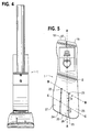
- a prosthetic foot 1 in the example embodiment of Figures 3-5 is seen to comprise a longitudinally extending foot keel 2 having a forefoot portion 3 at one end, a hindfoot portion 4 at an opposite end and an upwardly arched midfoot portion 5 extending between the forefoot and hindfoot portions.
- the midfoot portion 5 is upward convexly curved over its entire longitudinal extent between the forefoot and hindfoot portions in the example embodiment.
- An upstanding calf shank 6 of the foot 1 is attached at a portion of a downward convexly curved lower end 7 thereof to a proximate, posterior surface of the keel midfoot portion 5 by way of a releasable fastener 8 and coupling element 11.
- the fastener 8 is a single bolt with nut and washers in the example embodiment, but could be a releasable clamp or other fastener for securely positioning and retaining the calf shank on the foot keel when the fastener is tightened.
- a longitudinally extending opening 9 is formed in a proximate, posterior surface of the keel midfoot portion 5, see Figure 8 .
- a longitudinally extending opening 10 is also formed in the curved lower end 7 of the calf shank 6 like that shown in Figure 15 , for example.
- the releasable fastener 8 extends through the openings 9 and 10 which permit adjusting the alignment of the calf shank and the foot keel with respect to one another in the longitudinal direction, A-A in Figure 5 , when the fastener 8 is loosened or released for tuning the performance of the prosthetic foot to be task specific.
- the fastener 8, coupling element 11 and longitudinally extending openings 9 and 10 constitute an adjustable fastening arrangement for attaching the calf shank to the foot keel to form an ankle joint area of the prosthetic foot.
- the alignment capability of the calf shank and foot keel in the prosthetic foot of the invention allows the radii to be shifted so that horizontal or vertical linear velocities with the foot in athletic activities are affected.
- an alignment change can be made to affect the relationship of the calf shank's radius and the foot keel radius. That is, to improve the horizontal linear velocity characteristic, the bottom radius R 2 , of the foot k eel, is made more distal than its start position, Figure 2 as compared with Figure 1 . This changes the dynamic response characteristics and motion outcomes of the foot 1 to be more horizontally directed-and as a result greater horizontal linear velocity can be achieved with the same applied forces.
- the amputee can, through practice, find a setting for each activity that meets his/her needs as these needs relate to horizontal and vertical linear velocities.
- the coupling element 11 is a plastic or metal alloy alignment coupling (see Figures 3 , 4 and 23 ), or a resilient coupling element introducing a subtalar joint as in the example embodiment of Figs. 28-33 as discussed hereinafter, sandwiched between the attached foot keel 2 and calf shank 6.
- the releasable fastener 8 in Figs. 3 and 4 extends through a hole 12 in the coupling element.
- the coupling element extends along the attached portion of the calf shank and the proximate, posterior surface of the keel midfoot portion 5.
- the curved lower end 7 of the calf shank 6 is in the shape of a parabola with the smallest radius of curvature of the parabola located at the lower end and extending upwardly, and initially anteriorly in the parabola shape.
- a posteriorly facing concavity is formed by the curvature of the calf shank as depicted in Figure 3 .
- the parabola shape is advantageous in that it has increased dynamic response characteristics in creating both improved horizontal linear velocity associated with the relatively larger radii proximal terminal end thereof, while having a smaller radius of curvature at its lower end for quicker response characteristics.
- the larger radii of curvature at the upper end of the parabola shape enable the tangential line A, explained with reference to Figures 1 and 2 , to remain more vertically oriented with changes in alignment, which creates improved horizontal linear velocity.
- a pylon adapter 13 is connected to the upper end of the calf shank 6 by fasteners 14.
- the adapter 13 in turn is secured to the lower end of pylon 15 by fasteners 16.
- Pylon 15 is secured to the lower limb of the amputee by a supporting structure (not shown) attached to the leg stump.
- the forefoot, midfoot and hindfoot portions of the foot keel 2 are formed of a single piece of resilient material in the example embodiment.
- a solid piece of material, plastic in nature, having shape-retaining characteristics when deflected by the ground reaction forces can be employed.
- the foot keel and also the calf shank can be formed of laminated composite material having reinforcing fiber laminated with polymer matrix material.
- a high strength graphite, laminated with epoxy thermosetting resins, or extruded plastic utilized under the tradename of Delran, or degassed polyurethane copolymers may be used to form the foot keel and also the calf shank.
- the functional qualities associated with these materials afford high strength with low weight and minimal creep.
- thermosetting epoxy resins are laminated under vacuum utilizing prosthetic industry standards.
- the polyurethane copolymers can be poured into negative molds and the extruded plastic can be machined.
- Each material of use has its advantages and disadvantages.
- the laminated composite material for the foot keel and the calf shank can also advantageously be a thermo-formed (prepreg) laminated composite material manufactured per industry standards, with reinforcing fiber and a thermoplastic polymer matrix material for superior mechanical expansion qualities.
- preg thermo-formed laminated composite material manufactured per industry standards, with reinforcing fiber and a thermoplastic polymer matrix material for superior mechanical expansion qualities.
- a suitable commercially available composite material of this kind is CYLON ® made by Cytec Fiberite Inc. of Havre de Grace, Maryland.
- the resilient material's physical properties as they relate to stiffness, flexibility and strength are all determined by the thickness of the material. A thinner material will deflect easier than a thicker material of the same density.
- the material utilized, as well as the physical properties, are associated with the stiffness to flexibility characteristics in the prosthetic foot keel and calf shank.
- the thickness of the foot keel and calf shank are uniform or symmetrical in the example embodiment of Figures 3-5 , but the thickness along the length of these components can be varied as discussed below, such as by making the hindfoot and forefoot areas thinner and more responsive to deflection in the midfoot region.
- the midfoot portion 5 is formed by a longitudinal arch such that the medial aspect of the longitudinal arch has a relatively higher dynamic response capability than the lateral aspect of the longitudinal arch.
- the medial aspect of the longitudinal arch concavity is larger in radius than the lateral aspect thereof.
- the posterior end 17 of the hindfoot portion 4 is shaped in an upwardly curved arch that reacts to ground reaction forces during heel strike by compressing for shock absorption.
- the heel formed by the hindfoot portion 4 is formed with a posterior lateral corner 18 which is more posterior and lateral than the medial corner 19 to encourage hindfoot eversion during initial contact phase of gait.
- the anterior end 20 of the forefoot portion 3 is shaped in an upwardly curved arch to simulate the human toes being dorsiflexed in the heel rise toe off position of the late stance phase of gait. Rubber or foam pads 53 and 54 are provided on the lower forefoot and hindfoot as cushions.
- Improved biplanar motion capability of the prosthetic foot is created by medial and lateral expansion joint holes 21 and 22 extending through the forefoot portion 3 between dorsal and plantar surfaces thereof.
- Expansion joints 23 and 24 extend forward from respect ones of the holes to the anterior edge of the forefoot portion to form medial, middle and lateral expansion struts 25-27 which create improved biplanar motion capability of the forefoot portion of the foot keel.
- the expansion joint holes 21 and 22 are located along a line, B-B in Figure 5 , in the transverse plane which extends at an angle ⁇ of 35° to the longitudinal axis A-A of the foot keel with the medial expansion joint hole 21 more anterior than the lateral expansion joint hole 22.
- the expansion joint holes 21 and 22 as projected on a sagittal plane are inclined at an angle of 45° to the transverse plane with the dorsal aspect of the holes being more anterior than the plantar aspect.
- the distance from the releasable fastener 8 to the lateral expansion joint hole 22 is shorter than the distance from the releasable fastener to the medial expansion joint hole 21 such that the lateral portion of the prosthetic foot 1 has a shorter toe lever than the medial for enabling midfoot high and low dynamic response.
- the anterior of the hindfoot portion 4 of the foot keel 2 further includes an expansion joint hole 28 extending through the hindfoot portion 4 between dorsal and plantar surfaces thereof.
- An expansion joint 29 extends posteriorly from the hole 28 to the posterior edge of the hindfoot portion to form expansion struts 30 and 31.
- a dorsal aspect of the midfoot portion 5 and the forefoot portion 3 of the foot keel 2 form the upwardly facing concavity, 32 in Figure 3 , so that it mimics in function the fifth ray axis of motion of a human foot. That is, the concavity 32 has a longitudinal axis C-C which is oriented at an angle ⁇ of 150° to 35° to the longitudinal axis A-A of the foot keel with the medial being more anterior than the lateral to encourage fifth ray motion in gait as in the oblique low gear axis of rotation of the second to fifth metatarsals in the human foot.
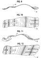
- FIG. 6 and 7 Another foot keel 33 of the invention, especially for sprinting, may be used in the prosthetic foot of the invention, see Figures 6 and 7 .
- the body's center of gravity in a sprint becomes exclusively sagittal plane oriented.
- the prosthetic foot does not need to have a low dynamic response characteristic.
- the 15°-35° external rotation orientation of the longitudinal axis of the forefoot, midfoot concavity as in foot keel 2 is not needed. Rather, the concavity's longitudinal axis D-D orientation should become parallel to the frontal plane as depicted in Figures 6 and 7 . This makes the sprint foot respond in a sagittal direction only.
- the orientation of the expansion joint holes 34 and 35 in the forefoot and midfoot portions, along line E-E, is parallel to the frontal plane, i.e., the lateral hole 35 is moved anteriorly and in line with the medial hole 34 and parallel to the frontal plane.
- the anterior terminal end 36 of the foot keel 33 is also made parallel to the frontal plane.
- the posterior terminal heel area 37 of the foot keel is also parallel to the frontal plane.
- Another variation in the sprint foot keel 33 is in the toe, ray region of the forefoot portion of the foot where 15° of dorsiflexion in the foot keel 2 are increased to 25-40° of dorsiflexion in foot keel 33.
- Figures 9 and 10 show an additional foot keel 38 of the invention for the prosthetic foot particularly useful for sprinting by an amputee that has had a Symes amputation of the foot.
- the midfoot portion of the foot keel 38 includes a posterior, upwardly facing concavity 39 in which the curved lower end of the calf shank is attached to the foot keel by way of the releasable fastener.
- This foot keel can be utilized by all lower extremity amputees.
- the foot keel 38 accommodates the longer residual limb associated with the Symes level amputee. Its performance characteristics are distinctively quicker in dynamic response capabilities. Its use is not specific to this level of amputation.
- the foot keel 40 in the example embodiment of Figures 11 and 12 also has a concavity 41 for a Symes amputee, the foot keel providing the prosthetic foot with high low dynamic response characteristic as well as biplanar motion capabilities like those of the example embodiment in Figures 3-5 and 8 .
- the functional characteristics of the several foot keels for the prosthetic foot 1 are associated with the shape and design features as they relate to concavities, convexities, radii size, expansion, compression, and material physical properties - all of these properties relating, to reacting to, ground forces in walking, running and jumping activities.
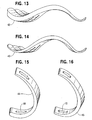
- the foot keel 42 in Figure 13 is like that in the example embodiment of Figures 3-5 and 8 , except that the thickness of the foot keel is tapered from the midfoot portion to the posterior of the hindfoot.
- the foot keel 43 in Figure 14 has its thickness progressively reduced or tapered at both its anterior and posterior ends. Similar variations in thickness are shown in the calf shank 44 of Figure 14 and the calf shank 45 of Figure 16 which may be used in the prosthetic foot 1.
- Each design of the foot keel and calf shank create different functional outcomes, as these function outcomes relate to the horizontal and vertical linear velocities which are specific to improving performance in varied athletic related tasks.
- the capability of multiple calf shank configurations and adjustments in settings between the foot keel and the calf shank create a prosthetic foot calf shank relationship that allows the amputee and/or the prosthetist the ability to tune the prosthetic foot for maximum performance in a selected one of a wide variety of sport and recreational activities.
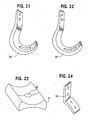
- calf shanks for the prosthetic foot 1 are illustrated in Figures 17-22 and include C-shaped calf shanks 46 and 47, S-shaped calf shanks 48 and 49 and J-shaped calf shanks 50 and 51.
- the upper end of the calf shank could also have a straight vertical end with a pyramid attachment plate attached to this proximal terminal end for connection to a prosthetic socket on the leg stump of the user, for example.
- a male pyramid could be bolted to and through this vertical end of the calf shank.
- Plastic or aluminum fillers to accept the proximal male pyramid and the distal foot keel could also be provided in the elongated openings at the proximal and distal ends of the calf shank.
- the prosthetic foot of the invention is a modular system preferably constructed with standardized units or dimensions for flexibility and variety in use.
- the left side of the right and left prosthetic foot calf shanks can be made thinner than the right side and the amputee runner's curve performance could be improved.
- the foot keels 2, 33, 38, 42, 43 and 71 in the several embodiments are each 29 cm long with the proportions of the shoe 1 shown to scale in Figures 3 , 4 and 5 , and in the several views of the different calf shanks and foot keels.
- the specific dimensions of the prosthetic foot can be varied depending on the size, weight and other characteristics of the amputee being fitted with the foot.
- the stance phase of walking/running activities can be further broken down into deceleration and acceleration phases.
- the foot pushes anteriorly on the ground and the ground pushes back in an equal and opposite direction - that is to say the ground pushes posteriorly on the prosthetic foot.
- This force makes the prosthetic foot move.
- the stance phase analysis of walking and running activities begins with the contact point being the posterior lateral corner 18, Figs. 3 and 18 , which is offset more posteriorly and laterally than the medial side of the foot. This offset at initial contact causes the foot to evert and the calf shank to plantar flex.
- the calf shank always seeks a position that transfers the body weight through its shank, e.g., it tends to have its long vertical member in a position to oppose the ground forces. This is why it moves posteriorly-plantar flexes to oppose the ground reaction force which is pushing posteriorly on the foot.
- the ground forces cause the calf shank to compress with the proximal end moving posteriorly.
- the calf shank lower tight radius compresses simulating human ankle joint plantar flexion and the forefoot is lowered by compression to the ground.
- the posterior aspect of the top of the foot keel 2 compresses upward through compression. Both of these compressive forces act as shock absorbers. This shock absorption is further enhanced by the offset posterior lateral heel 18 which causes the foot to evert, which also acts as a shock absorber, once the calf shank has stopped moving into plantar flexion and with the ground pushing posteriorly on the foot.
- the compressed members of the foot keel and calf shank then start to unload - that is they seek their original shape and the stored energy is released - which causes the calf shank proximal end to move anteriorly in an accelerated manner.
- the ground forces change from pushing posteriorly to pushing vertically upward against the foot.
- the prosthetic foot has posterior and anterior plantar surface weight bearing areas and these areas are connected by a non-weight bearing long arch shaped midportion, the vertically directed forces from the prosthesis cause the long arch shaped midportion to load by expansion.
- the posterior and anterior weight-bearing surfaces diverge.
- the long arch of the foot keel and the calf shank resist expansion of their respective structures.
- the calf shank anterior progression is arrested and the foot starts to pivot off the anterior plantar surface weight-bearing area.
- the expansion of the midfoot portion of the foot keel has as high and low response capability in the case of the foot keels in the example embodiments of Figures 3-5 and 8 , Figures 11 and 12 , Figure 13 and Figure 14 , and Figures 28-33 .
- the midfoot forefoot transitional area of these foot keels is deviated 15° to 35° externally from the long axis of the foot, the medial long arch is longer than the lateral long arch. This is important because in the normal foot, during acceleration or deceleration, the medial aspect of the foot is used.
- the prosthetic foot longer medial arch has greater dynamic response characteristic than the lateral.
- the lateral shorter toe lever is utilized when walking or running at slower speeds.
- the body's center of gravity moves through space in a sinusoidal curve. It moves medial, lateral, proximal and distal. When walking or running at slower speeds, the body's center of gravity moves more medial and lateral than when walking or running fast.
- momentum or inertia is less and the ability to overcome a higher dynamic response capability is less.
- the prosthetic foot of the invention is adapted to accommodate these principles in applied mechanics.
- the ray region of the forefoot portion is dorsiflexed 15°-35°. This upwardly extending arc allows the anteriorly directed ground forces to compress this region of the foot. This compression is less resisted than expansion and a smooth transition occurs to the swing phase of gait and running with the prosthetic foot.
- the expanded calf shank and the expanded midfoot long arch release their stored energy adding to the propulsion of the amputee's body center of gravity.
- the posterior aspect of the hindfoot and the forefoot region of the foot keel incorporate expansion joint holes and expansion joint struts in several of the embodiments as noted previously.
- the orientation of the expansion joint holes act as a mitered hinge and biplanar motion capabilities are improved for improving the total contact characteristics of the plantar surface of the foot when walking on uneven terrain.
- the Symes foot keels in Figures 9-12 are distinctively different in dynamic response capabilities - as these capabilities are associated with walking, running and jumping activities. These foot keels differ in four distinct features. These include the presence of a concavity in the proximate, posterior of the midfoot portion for accommodating the Symes distal residual limb shape better than a flat surface.
- the alignment concavity requires that the corresponding anterior and posterior radii of the arched foot keel midportion be more aggressive and smaller in size. As a consequence, all of the midfoot long arch radii and the hindfoot radii are tighter and smaller. This significantly affects the dynamic response characteristics. The smaller radii create less potential for a dynamic response.
- the prosthetic foot responds quicker to all of the aforementioned walking, running and jumping ground forces. The result is a quicker foot with less dynamic response.
- the human foot is a multi-functional unit - it walks, runs and jumps.
- the human tibia fibula calf shank structure on the other hand is not a multi-functional unit. It is a simple lever which applies its forces in walking, running and jumping activities parallel to its long proximal-distal orientation. It is a non-compressible structure and it has no potential to store energy.
- the prosthetic foot of the invention has dynamic response capabilities, as these dynamic response capabilities are associated with the horizontal and vertical linear velocity components of athletic walking, running and jumping activities and out-performing the human tibia and fibula.
- the fastener 8 is loosened and the alignment of the calf shank and the foot keel with respect to one another is adjusted in the longitudinal direction of the foot keel.
- Such a change is shown in connection with Figures 1 and 2 .
- the calf shank is then secured to the foot keel in the adjusted position with the fastener 8.
- the bolt of the fastener 8 slides relative to one or both of the opposed, relatively longer, longitudinally extending openings 9 and 10 in the foot keel and calf shank, respectively.
- An alignment change that improves the performance characteristic of a runner who makes initial contact with the ground with the foot flat as in sprinting is one wherein the foot keel is slid anterior relative to the calf shank and the foot plantar flexed on the calf shank.
- This new relationship improves the horizontal component of running. That is, with the calf shank plantar flexed to the foot, and the foot making contact with the ground in a foot flat position as opposed to initially heel contact, the ground immediately pushes posteriorly on the foot that is pushing anteriorly on the ground. This causes the calf shank to move rapidly forward (by expanding) and downwardly. Dynamic response forces are created by expansion which resists the calf shank's direction of initial movement.
- the foot pivots over the metatarsal plantar surface weight-bearing area.
- This causes the midfoot region of the keel to expand which is resisted more than compression.
- the net effect of the calf shank expansion and the midfoot expansion is that further anterior progression of the calf shank is resisted which allows the knee extenders and hip extenders in the user's body to move the body's center of gravity forward and proximal in a more efficient manner (i.e., improved horizontal velocity).
- an alignment change of the calf shank and foot keel is made.
- Advantage is taken of the foot keel having all of its concavities with their longitudinal axis orientation parallel to the frontal plane.
- the calf shank is plantar flexed and slid posterior on the foot keel. This lowers the distal circles even further than on the flat foot runner with the multi-use foot keel like that in Figures 3-5 and 8 , for example. As a consequence, there is even greater horizontal motion potential and the dynamic response is directed into this improved horizontal capability.
- the sprinters have increased range of motion, forces and momentum (inertia) - momentum being a prime mover. Since their stance phase deceleration phase is shorter than their acceleration phase, increased horizontal linear velocities are achieved. This means that at initial contact, when the toe touches the ground, the ground pushes posteriorly on the foot and the foot pushes anteriorly on the ground.
- the calf shank which has increased forces and momentum is forced into even greater flexion and downward movement than the initial contact foot flat runner. As a consequence to these forces, the foot's long arch concavity is loaded by expansion and the calf shank is loaded by expansion. These expansion forces are resisted to a greater extent than all the other previously mentioned forces associated with running.
- the dynamic response capability of the foot is proportional to the force applied.
- the human tibia fibula calf shank response is only associated with the energy force potential - it is a straight structure and it cannot store energy.
- These expansion forces in the prosthetic foot of the invention in sprinting are greater in magnitude than all the other previously mentioned forces associated with walking and running.
- the dynamic response capability of the foot is proportional to the applied forces and increased amputee athletic performance, as compared with human body function, is possible.
- the prosthetic foot 53 depicted in Fig. 25 is like that in Fig. 3 except for the adjustable fastening arrangement between the calf shank and the foot keel and the construction of the upper end of the calf shank for connection to the lower end of a pylon.
- the foot keel 54 is adjustably connected to the calf shank 55 by way of plastic or aluminum coupling element 56.
- the coupling element is attached to the foot keel and calf shank by respective releasable fasteners 57 and 58 which are spaced from one another in the coupling element in a direction along the longitudinal direction of the foot keel.
- the fastener 58 joining the coupling element to the calf shank is more posterior than the fastener 57 joining the foot keel and the coupling element.
- the upper end of the calf shank 55 is formed with an elongated opening 59 for receiving a pylon 15.
- the pylon can be securely clamped to the calf shank by tightening bolts 60 and 61 to draw the free side edges 62 and 63 of the calf shank along the opening together.
- This pylon connection can be readily adjusted by loosening the bolts, telescoping the pylon relative to the calf shank to the desired position and reclamping the pylon in the adjusted position by tightening the bolts.
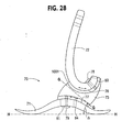
- the prosthetic foot 70 shown in Figs. 28-33 is similar to those in Figs. 3-5 , 8, 23 and 24 and Figs. 25-27 in that it includes a foot keel 71 and a calf shank 72 connected to the foot keel by way of a coupling element 73.
- the coupling element is formed of a resilient material forming a joint permitting closed kinetic chain motion of the prosthetic foot in gait. More particularly, the joint of the coupling element has a joint axis, G-G in Figs. 28 and 33 , defined by the dog bone shaped structure of the coupling element.
- the axis G-G is oriented for permitting motion of the foot about the joint axis which is at least primarily in the frontal and transverse planes, although in the example embodiment some motion in the sagittal plane occurs.
- the joint axis G-G as projected on a sagittal plane preferably makes an angle ⁇ within the range of 25 to 42° with respect to a transverse plane, represented by H-H in Fig. 28 .
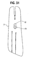
- the joint axis G-G as projected on a transverse plane is preferably externally rotated at an angle ⁇ ' within the range of 16 to 23° with respect to the longitudinal axis of the foot, A-A, as shown in Fig. 33 .
- the joint axis G-G of the coupling element of the foot runs from posterior, plantar and lateral to anterior, dorsal and medial.
- the coupling device is preferably made of carbon and a high strength polyurethane elastomer material but other materials providing the requisite resilience and strength could be used.
- the design features of the coupling device impart subtalar joint functional motion outcome potential. That is to say that the coupling device is oriented and designed so that it has an axis G-G which affects motion potential outcomes. The motion potential outcomes are to be specifically oriented to mimic human subtalar joint function in human gait and running activities.
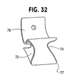
- the coupling element has the dog bone shaped structure ( Fig. 32 ), as a result of concavely curved lateral and medial side surfaces 74 and 75 of the coupling element.
- the coupling element also has proximal calf shank and distal foot keel carbon plastic reinforced attachment plates 76 and 77 secured thereto by which the coupling element mates complementarily with and is attached between the proximal surface of the foot keel and the distal surface of the calf shank using releasable fasteners 78 and 79 which extend through longitudinally directed slots 80 and 81 in the foot keel and calf shank for adjustability as in the previously described embodiments.
- the dog bone shaped structure incorporates in its design the longitudinal axis of rotation G-G which relates to the potential for motion outcomes as described above.
- the orientation of the axis of rotation G-G of the coupling device is preferably as close to anatomically correct as possible.
- the axis of motion orientation is preferably deviated in the sagittal plane with respect to a transverse plane (oblique axis G-G in Fig. 28 is deviated by angle ⁇ ) and as projected on a transverse plane is deviated on the longitudinal axis of the foot (longitudinal axis G-G in Fig. 33 is deviated by angle ⁇ ').
- ⁇ longitudinal axis of the foot
- transverse plane motions (19°) of the calf shank that occur during the stance phase of gait will be transferred into prosthetic foot inversion and eversion motions.
- a 25-42° oblique axis of orientation of the axis G-G is provided in the high performance foot. It has been found that the oblique axis of orientation improves both frontal and transverse plane motion outcomes.
- a 25° oblique axis of orientation of the axis G-G will improve frontal plane motion outcomes at the expense of transverse plane motion outcomes.
- a 42° oblique axis of orientation of axis G-G will improve the transverse plane motion at the expense of frontal plane motion.
- the oblique axis G-G of the coupling element of the foot is deviated in the sagittal plane so that the anterior is more proximal than the posterior. See Fig. 28 .
- the longitudinal axis of orientation of the axis G-G of the coupling device in use in the foot is preferably anatomically correct. It is deviated in the transverse plane 16-23° of external rotation to the long axis of the foot as noted above.
- the anterior aspect of the longitudinal axis of axis G-G is medial.
- the longitudinal axis of orientation of the axis G-G of the coupling device could also be located sagittally, e.g., with no transverse plane deviation from the longitudinal axis of the foot, or parallel to the sagittal plane and longitudinal axis of the foot.
- the actual material utilized for the coupling element in the example embodiment is a variable durometer polyurethane elastomer.
- the prosthetic foot 70' in Fig. 34 is a variation of the prosthetic foot of Figs. 28-33 where the foot keel 71' and calf shank 72' are integrally joined by the coupling element 73', which can be formed of a polyurethane elastomer by molding, for example, to bond the calf shank and foot keel to one another.
- the coupling element has a joint axis G-G oriented for permitting motion of the foot about the joint axis which is at least primarily in the frontal and transverse planes as explained with reference to the foot 70 in Figs. 28-33 .
- the foot 70' is not adjustable.
- the subtalar joint polyurethane elastomer coupling element is located on the anterior half of the hindfoot portion and the posterior third of the midfoot portion of the foot keel, and on the posterior half of the calf shank with the proximal end of the calf shank 72' being generally vertically oriented.
- This one piece foot 70' is beneficial to a K1,2 level of amputee having fixed cadence rehabilitation potential.
- Fig. 35 illustrates a further variation of the prosthetic foot of Figs. 28-33 wherein the foot comprises two pieces, e.g., the coupling element 73" is integrally formed as by molding to the calf shank while adjustably connected to the foot keel 71 as in the prosthetic foot 70.
- the single longitudinal adjustment can be utilized to orient the oblique axis G-G of the subtalar joint of the coupling element.
- the foot 70" is useful for the amputee having a K2-3 level of rehabilitation potential.
- the foot 70 of Figs. 28-33 with its double longitudinal adjustability is utilized on the K3-4 amputee.
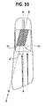
- the calf shank 72 of the prosthetic foot 70 of the embodiment of Figs. 28-33 also has longitudinally extending grooves or concavities 82 and corresponding longitudinally extending raised fins 83.
- these structural modifications 82 and 83 are located on the posteriorly facing concavity side of the calf shank 72. They decrease the resistance of the calf shank to compression forces.
- the grooves and fins are linear as shown but could be wavy or "s" shaped.
- the motion outcomes of the calf shank 72 by these structural modifications are tuned to achieve a decrease in compressive resistance of the calf shank as compared to expansion resistance, in response to ground force loading in walking, running and jumping activities.
- the power potential of the human calf musculature can be expressed as the cross-sectional area of the specific muscle and/or muscle group.
- the plantar flexor muscle group has approximately 130 cm of cross-sectional area.
- the dorsiflexor muscle group has approximately 35 cm cross-sectional area. This is a 3.7 to 1 ratio.
- the calf shank 72 responds to the initial contact ground reaction forces by resisting compression with a force which mimics the dorsiflexor muscle group's eccentric contraction that occurs in normal gait.
- the calf shank 72 resists expansion in the late stance phase of gate with a relative force which mimics the larger plantar flexor muscle group's corresponding eccentric contraction, which occurs in human gait from midstance to heel off.
- the calf shank 72 resistance to compression versus its resistance to expansion can be fine-tuned utilizing 82 and 83 so that humanoid functional motion outcomes can be achieved.
- the lower end of the calf shank in the prosthetic foot of the invention is not limited to a parabola shape or a generally parabola shape but can be otherwise downward convexly, curvilinearly configured to produce the desired motion outcomes of the foot when connected to the foot keel to form the ankle joint area of the foot.
- the various features of respective ones of the several embodiments can also be used in the other embodiments and with one another.
Landscapes
- Health & Medical Sciences (AREA)
- Transplantation (AREA)
- Life Sciences & Earth Sciences (AREA)
- Veterinary Medicine (AREA)
- Public Health (AREA)
- General Health & Medical Sciences (AREA)
- Animal Behavior & Ethology (AREA)
- Engineering & Computer Science (AREA)
- Vascular Medicine (AREA)
- Heart & Thoracic Surgery (AREA)
- Biomedical Technology (AREA)
- Oral & Maxillofacial Surgery (AREA)
- Cardiology (AREA)
- Orthopedic Medicine & Surgery (AREA)
- Chemical & Material Sciences (AREA)
- Medicinal Chemistry (AREA)
- Pharmacology & Pharmacy (AREA)
- Epidemiology (AREA)
- Prostheses (AREA)
- Orthopedics, Nursing, And Contraception (AREA)
- Thermotherapy And Cooling Therapy Devices (AREA)
- Finger-Pressure Massage (AREA)
Claims (18)
- Eine Fussprothese (70, 70', 70'') umfassend:ein längs ausgedehnter Fusskiel (71, 71');ein Kopplungselement (73, 73', 73"), welches mit dem Fusskiel verbunden ist; undein federnder, aufrechter Wadenschaft (72, 72') mit einem unteren Ende, dass mittels des Kopplungselements mit dem Fusskiel (71, 71') verbunden ist, um ein Fussgelenkbereich des Fusses zu bilden, und einem oberen Ende zum Verbinden mit einer Abstützanordnung am Bein des Amputierten;dadurch gekennzeichnet, dass das untere Ende des Wadenschafts nach unten und anterior zugewandt, konvex gekrümmt ist, und wobei das Kopplungselement ein elastisches Material umfasst, welches ein Gelenk bildet, dass einen geschlossenen Bewegungsablauf der Fussprothese beim Gang ermöglicht, wobei das Gelenk eine Gelenkachse (G-G) aufweist, die derart ausgerichtet ist, dass eine Bewegung des Fusses um die Gelenkachse möglich ist, welche mindestens primär in den frontalen und transversalen Ebenen ist.
- Die Fussprothese nach Anspruch 1, wobei die auf eine sagittale Ebene projizierte Gelenkachse (G-G) bezüglich einer transversalen Ebene einen Winkel (Δ) im Bereich von 25-42° einschliesst.
- Die Fussprothese nach Anspruch 2, umfassend Mittel (79, 81, 84) zur Veränderung des Neigungswinkels (Δ), welcher die auf eine sagittale Ebene projizierte Gelenkachse (G-G) bezüglich einer transversalen Ebene einschliesst.
- Die Fussprothese nach Anspruch 1, wobei die Gelenkachse (G-G) derart ausgerichtet ist, dass auch eine Bewegung des Fusses um die Gelenkachse in der sagittalen Ebene möglich ist.
- Die Fussprothese nach Anspruch 1, wobei die Gelenkachse (G-G) von posterior, plantar und lateral nach anterior, dorsal und medial verläuft.
- Die Fussprothese nach Anspruch 1, wobei die auf eine transversale Ebene projizierte Gelenkachse (G-G) extern rotiert wird um einem Winkel (Δ') im Bereich vom 16-23° bezüglich der Längsachse (A-A) des Fusses.
- Die Fussprothese nach Anspruch 1, wobei mediale (75) und laterale (74) Seitenflächen des Kopplungselements entlang der Gelenkachse konkav gekrümmt sind, um Kräfte bei der Bewegung des Fusses um die Gelenkachse zu übertragen und zu absorbieren.
- Die Fussprothese nach Anspruch 1, wobei das Gelenk zur Nachahmung eines Sprunggelenks ausgeführt ist, um zu ermöglichen, dass die Fussprothese wie ein menschlicher Fuss funktioniert.
- Die Fussprothese nach Anspruch 1, weiter umfassend eine einstellbare Befestigungsanordnung (78, 79, 80, 81, 84), um das Einstellen der Ausrichtung des Wadenschafts und des Fusskiels in Längsrichtung (A-A) des Fusses zueinander zu ermöglichen, um die Eigenschaften der Fussprothese abzustimmen.
- Die Fussprothese nach Anspruch 9, wobei die einstellbare Befestigungsanordnung mindestens ein lösbares Befestigungselement (79), welches das Kopplungselement und den Fusskiel verbindet, und eine im Fusskiel längs ausgedehnte Öffnung (81), durch welche sich das Befestigungselement erstreckt, um die Einstellung der Ausrichtung des Kopplungselements und des Wadenschafts zu ermöglichen, umfasst.
- Die Fussprothese nach Anspruch 1, wobei das obere Ende (Fig. 21, 22) des Wadenschafts ein gerades, vertikales oberes Ende ist.
- Die Fussprothese nach Anspruch 1, wobei das konvex gekrümmte untere Ende des Wadenschafts einen Krümmungsradius aufweist, welcher vom gekrümmten unteren Ende des Wadenschafts her aufwärts zunimmt.
- Die Fussprothese nach Anspruch 1, wobei das untere Ende des Wadenschafts hauptsächlich parabel-förmig ist, wobei sich der kleinste Krümmungsradius hiervon am unteren Ende befindet, und sich aufwärts und anfänglich anterior davon erstreckt.
- Die Fussprothese nach Anspruch 13, wobei durch die Krümmung des Wadenschafts eine posterior zugewandte Konkavität ausgebildet ist, wobei die posterior zugewandte Konkavität eine Oberfläche mit einer Vielzahl von darauf geformten längsausgedehnten Kerben und Rippen aufweist, um die elastische Kompression des Wadenschafts zu erleichtern und zugleich dehnungsbeständig auf Kräfte zu reagieren, welche auf den Wadenschaft einwirken während des Gebrauchs der Fussprothese.
- Die Fussprothese nach Anspruch 1, wobei das Kopplungselement integral mit mindestens dem Fusskiel oder dem Wadenschaft ausgebildet ist.
- Die Fussprothese nach Anspruch 1, wobei das Kopplungselement je mit dem Fusskiel und dem Wadenschaft verbunden ist, um das untere Ende des Wadenschafts an den Fusskiel zu befestigen.
- Die Fussprothese nach Anspruch 1, wobei:der Wadenschaft und der Fusskiel jeweils zugewandte, konvex gekrümmte Flächen aufweisen, deren Radien (R1, R2) und Beziehung eine dynamische Reaktion und Bewegungsauswirkung (B, B1) der Fussprothese beim Gang beeinflussen, und wobei die Fussprothese weiter umfasst:eine einstellbare Befestigungsanordnung (78, 79, 80, 81, 84) zur Befestigung des Wadenschafts am Fusskiel, wobei die Befestigungsanordnung das Einstellen der Beziehung der jeweiligen konvex gekrümmten Flächen des Fusskiels und Wadenschafts ermöglicht, um die Eigenschaften der Fussprothese abzustimmen.
- Eine Fussprothese nach Anspruch 17, wobei die jeweiligen konvex gekrümmten Flächen die dorsale Fläche eines Mittelfussteils des Fusskiels und eine abwärts und anterior zugewandte Fläche des Wadenschafts umfassen.
Applications Claiming Priority (3)
| Application Number | Priority Date | Filing Date | Title |
|---|---|---|---|
| US820895 | 2001-03-30 | ||
| US09/820,895 US6562075B2 (en) | 2001-03-30 | 2001-03-30 | Prosthetic foot with tunable performance |
| PCT/US2002/009573 WO2002078567A2 (en) | 2001-03-30 | 2002-03-29 | Prosthetic foot with tunable performance |
Publications (3)
| Publication Number | Publication Date |
|---|---|
| EP1372546A2 EP1372546A2 (de) | 2004-01-02 |
| EP1372546A4 EP1372546A4 (de) | 2008-12-10 |
| EP1372546B1 true EP1372546B1 (de) | 2011-02-23 |
Family
ID=25231989
Family Applications (6)
| Application Number | Title | Priority Date | Filing Date |
|---|---|---|---|
| EP02713785A Expired - Lifetime EP1372547B1 (de) | 2001-03-30 | 2002-03-08 | Fussprothese mit einstellbarer leistung |
| EP02733905A Expired - Lifetime EP1372546B1 (de) | 2001-03-30 | 2002-03-29 | Fussprothese mit einstellbarer leistung |
| EP02757836A Withdrawn EP1372548A4 (de) | 2001-03-30 | 2002-03-29 | Fussprothese mit einstellbarer leistung |
| EP02725392A Withdrawn EP1372545A4 (de) | 2001-03-30 | 2002-03-29 | Fussprothese mit einstellbarer leistung |
| EP02778336A Withdrawn EP1549265A4 (de) | 2001-03-30 | 2002-09-26 | Fussprothese mit einstellbarer leistung |
| EP03714438A Withdrawn EP1613250A4 (de) | 2001-03-30 | 2003-03-31 | Fussprothese mit einstellbarer leistung und verbesserter vertikaler belastungs/stossdämpfung |
Family Applications Before (1)
| Application Number | Title | Priority Date | Filing Date |
|---|---|---|---|
| EP02713785A Expired - Lifetime EP1372547B1 (de) | 2001-03-30 | 2002-03-08 | Fussprothese mit einstellbarer leistung |
Family Applications After (4)
| Application Number | Title | Priority Date | Filing Date |
|---|---|---|---|
| EP02757836A Withdrawn EP1372548A4 (de) | 2001-03-30 | 2002-03-29 | Fussprothese mit einstellbarer leistung |
| EP02725392A Withdrawn EP1372545A4 (de) | 2001-03-30 | 2002-03-29 | Fussprothese mit einstellbarer leistung |
| EP02778336A Withdrawn EP1549265A4 (de) | 2001-03-30 | 2002-09-26 | Fussprothese mit einstellbarer leistung |
| EP03714438A Withdrawn EP1613250A4 (de) | 2001-03-30 | 2003-03-31 | Fussprothese mit einstellbarer leistung und verbesserter vertikaler belastungs/stossdämpfung |
Country Status (12)
| Country | Link |
|---|---|
| US (5) | US6562075B2 (de) |
| EP (6) | EP1372547B1 (de) |
| JP (5) | JP4328095B2 (de) |
| CN (6) | CN100522109C (de) |
| AT (2) | ATE506036T1 (de) |
| AU (4) | AU2002255958A1 (de) |
| CA (6) | CA2446768C (de) |
| DE (2) | DE60239792D1 (de) |
| DK (1) | DK1372547T3 (de) |
| ES (1) | ES2364815T3 (de) |
| RU (4) | RU2305516C2 (de) |
| WO (6) | WO2002078577A1 (de) |
Families Citing this family (95)
| Publication number | Priority date | Publication date | Assignee | Title |
|---|---|---|---|---|
| US7686848B2 (en) * | 2000-06-30 | 2010-03-30 | Freedom Innovations, Llc | Prosthetic foot with energy transfer |
| US7341603B2 (en) * | 2000-06-30 | 2008-03-11 | Applied Composite Technology, Inc. | Prosthetic foot with energy transfer including variable orifice |
| US7572299B2 (en) * | 2000-06-30 | 2009-08-11 | Freedom Innovations, Llc | Prosthetic foot with energy transfer |
| US20060241783A1 (en) * | 2000-06-30 | 2006-10-26 | Christensen Roland J | Variable resistance cell |
| US20050216098A1 (en) * | 2000-06-30 | 2005-09-29 | Roland J. Christensen | Variable resistance cell |
| US7410503B2 (en) * | 2001-03-30 | 2008-08-12 | Bioquest Prosthetics Llc | Prosthetic foot with tunable performance |
| CN1243521C (zh) * | 2000-12-22 | 2006-03-01 | 巴里·W·汤森 | 假脚 |
| US7108723B2 (en) * | 2000-12-22 | 2006-09-19 | Townsend Barry W | Prosthetic foot |
| US7611543B2 (en) * | 2001-03-30 | 2009-11-03 | Bioquest Prosthetics, Llc | Prosthetic foot with tunable performance |
| US6562075B2 (en) | 2001-03-30 | 2003-05-13 | Barry W. Townsend | Prosthetic foot with tunable performance |
| US7429272B2 (en) * | 2001-03-30 | 2008-09-30 | Bioquest Prosthetics Llc | Prosthetic foot with tunable performance |
| US7954502B2 (en) * | 2001-03-30 | 2011-06-07 | Bioquest Prosthetics, Llc | Mobility assistance apparatus |
| US7578852B2 (en) * | 2001-03-30 | 2009-08-25 | Bioquest Prosthetics, Llc | Prosthetic foot with tunable performance and improved vertical load/shock absorption |
| US7374578B2 (en) | 2001-03-30 | 2008-05-20 | Bioquest Prosthetics, Llc | Prosthetic foot with tunable performance |
| US8236062B2 (en) | 2001-03-30 | 2012-08-07 | Bioquest Prosthetics Llc | Prosthetic foot with tunable performance |
| US20060185703A1 (en) * | 2001-03-30 | 2006-08-24 | Townsend Barry W | Mobility assistance apparatus |
| US8070829B2 (en) * | 2003-09-30 | 2011-12-06 | Bioquest Prosthetics Llc | Prosthetic foot with tunable performance |
| US20070213841A1 (en) * | 2001-03-30 | 2007-09-13 | Townsend Barry W | Prosthetic foot with tunable performance |
| US7507259B2 (en) * | 2001-03-30 | 2009-03-24 | Bioquest Prosthetics, Llc | Prosthetic foot with tunable performance |
| US7087065B2 (en) | 2001-10-04 | 2006-08-08 | Ethicon, Inc. | Mesh for pelvic floor repair |
| US6702859B1 (en) * | 2002-08-22 | 2004-03-09 | Aldo A. Laghi | Dynamic prosthetic foot with multiple load points and anterior/posterior upper sections |
| US6793683B1 (en) * | 2002-08-22 | 2004-09-21 | Aldo A. Laghi | Prosthetic foot with medial/lateral stabilization |
| US7917468B2 (en) * | 2005-08-01 | 2011-03-29 | Seven Networks, Inc. | Linking of personal information management data |
| KR100980531B1 (ko) * | 2003-06-25 | 2010-09-06 | 조셉 스티븐 이간 | 몰드 제품 제조방법 |
| US8007544B2 (en) | 2003-08-15 | 2011-08-30 | Ossur Hf | Low profile prosthetic foot |
| US6942704B2 (en) * | 2003-08-29 | 2005-09-13 | S & L, Inc. | Prosthetic foot |
| US8574314B2 (en) * | 2003-09-30 | 2013-11-05 | Bioquest Prosthetics Llc | Resilient prosthetic and orthotic components which incorporate a plurality of sagittally oriented struts |
| US7520904B2 (en) * | 2003-10-21 | 2009-04-21 | Freedom Innovations, Llc | Prosthetic foot with an adjustable ankle and method |
| US7462201B2 (en) * | 2003-10-21 | 2008-12-09 | Freedom Innovations, Llc | Prosthetic foot with an adjustable ankle and method |
| JP2007530236A (ja) * | 2004-04-01 | 2007-11-01 | ダブリュ タウンゼンド、バリー | 調整可能機能を備えた義足 |
| US20050240284A1 (en) * | 2004-04-27 | 2005-10-27 | Allert Daniel A | Prosthetic foot devices |
| US7581454B2 (en) * | 2004-05-28 | 2009-09-01 | össur hf | Method of measuring the performance of a prosthetic foot |
| US7347877B2 (en) | 2004-05-28 | 2008-03-25 | össur hf | Foot prosthesis with resilient multi-axial ankle |
| DE102004031562A1 (de) * | 2004-06-29 | 2006-02-16 | Otto Bock Healthcare Ip Gmbh & Co. Kg | Künstlicher Fuß |
| JP2008537894A (ja) * | 2005-01-25 | 2008-10-02 | カレッジ パーク インダストリアー インコーポレイテッド | 背屈を向上させた踝下非関節運動型義足 |
| US20060212131A1 (en) * | 2005-03-15 | 2006-09-21 | Curtis Michael J | Energy returning prosthetic foot |
| WO2006107329A1 (en) * | 2005-04-01 | 2006-10-12 | Townsend Barry W | Prosthetic foot with tunable performance |
| US7618463B2 (en) * | 2005-07-11 | 2009-11-17 | össur hf | Energy returning prosthetic joint |
| US20070100466A1 (en) * | 2005-09-24 | 2007-05-03 | Allert Daniel A | Prosthetic foot devices |
| US20070169567A1 (en) * | 2006-01-20 | 2007-07-26 | Mts Systems Corporation | Duty cycle loading for orthopedic simulator |
| USD579115S1 (en) * | 2006-03-16 | 2008-10-21 | Otto Bock Healthcare Ip Gmbh & Co. Kg | Prosthesis |
| US7618464B2 (en) * | 2006-08-03 | 2009-11-17 | Freedom Innovations, Llc | Prosthetic foot with variable medial/lateral stiffness |
| US7824446B2 (en) * | 2006-12-06 | 2010-11-02 | Freedom Innovations, Llc | Prosthetic foot with longer upper forefoot and shorter lower forefoot |
| US7727285B2 (en) * | 2007-01-30 | 2010-06-01 | Freedom Innovations, Llc | Prosthetic foot with variable medial/lateral stiffness |
| US20080228288A1 (en) * | 2007-03-13 | 2008-09-18 | Ronald Harry Nelson | Composite Prosthetic Foot |
| US7794506B2 (en) * | 2007-09-18 | 2010-09-14 | Freedom Innovations, Llc | Multi-axial prosthetic ankle |
| US8034121B2 (en) * | 2008-04-18 | 2011-10-11 | Freedom Innovations, Llc | Prosthetic foot with two leaf-springs joined at heel and toe |
| US9011554B2 (en) * | 2008-07-25 | 2015-04-21 | Fillauer Composites Llc | High-performance multi-component prosthetic foot |
| DE102008060177A1 (de) * | 2008-12-02 | 2010-06-17 | Otto Bock Healthcare Gmbh | Künstlicher Fuß |
| EP2538890B1 (de) | 2010-02-23 | 2018-10-10 | Össur HF | Mittelfussgelenkform für fussprothesen sowie steuermechanismus und -system dafür |
| EP2538891B1 (de) * | 2010-02-26 | 2015-04-15 | Össur HF | Fussprothese mit gekrümmter aufteilung |
| US8500825B2 (en) | 2010-06-29 | 2013-08-06 | Freedom Innovations, Llc | Prosthetic foot with floating forefoot keel |
| DE102010034893A1 (de) | 2010-08-19 | 2012-02-23 | Medi Gmbh & Co. Kg | Fußprothese |
| US9060884B2 (en) | 2011-05-03 | 2015-06-23 | Victhom Human Bionics Inc. | Impedance simulating motion controller for orthotic and prosthetic applications |
| DE102011053765A1 (de) | 2011-09-20 | 2013-03-21 | Prosthetics-Solutions GmbH & Co KG | Fußfederanordnung und Prothesenfuß mit einer solchen Fußfederanordnung |
| EP2760379B1 (de) | 2011-09-26 | 2017-10-25 | Össur HF | Reibungsloser vertikaler aufhängmechanismus für fussprothesen |
| WO2013049852A2 (en) * | 2011-09-29 | 2013-04-04 | Phillips L Van | Prosthetic energy storing and releasing apparatus and methods |
| US9017421B2 (en) | 2011-12-01 | 2015-04-28 | össur hf | Prosthetic foot with dual foot blades and vertically offset toe |
| US8961618B2 (en) | 2011-12-29 | 2015-02-24 | össur hf | Prosthetic foot with resilient heel |
| USD714939S1 (en) * | 2012-06-01 | 2014-10-07 | össur hf | Prosthetic foot with a colored edge |
| CN102700648B (zh) * | 2012-06-14 | 2013-11-27 | 西北工业大学 | 一种仿袋鼠跳跃机器人的自适应变形脚 |
| CN102717846A (zh) * | 2012-06-21 | 2012-10-10 | 戴文钟 | 机器人脚掌结构 |
| US20140005801A1 (en) | 2012-06-27 | 2014-01-02 | Ossur Hf | Alignment adapter for prosthetic sport feet |
| US9259343B2 (en) | 2012-07-06 | 2016-02-16 | Newman Technologies LLC | Device for mitigating plantar fasciitis |
| WO2014022411A1 (en) | 2012-08-01 | 2014-02-06 | Ossur Hf | Prosthetic ankle module |
| USD718861S1 (en) * | 2013-02-25 | 2014-12-02 | Ossur Hf | Prosthetic foot component |
| EP3427702B1 (de) | 2013-02-26 | 2024-12-18 | Össur HF | Fussprothese mit verbesserter stabilität und elastischer energierückspeisung |
| CN103239307B (zh) * | 2013-04-24 | 2015-03-25 | 西南交通大学 | 一种助力型外骨骼用负重承载效率检测方法 |
| KR101512233B1 (ko) | 2013-08-07 | 2015-04-16 | 근로복지공단 | 탄성재가 주입된 다축인공발 |
| EP3099273A4 (de) * | 2014-01-29 | 2017-10-18 | Össur HF | Prothesenfüsse für sport |
| DE102014006571B3 (de) * | 2014-05-07 | 2015-08-06 | Otto Bock Healthcare Gmbh | Prothesenfuß |
| US9999524B2 (en) | 2014-06-30 | 2018-06-19 | össur hf | Prosthetic feet and foot covers |
| DE102014010938B4 (de) | 2014-07-28 | 2023-01-12 | Ottobock Se & Co. Kgaa | Prothesenfuß, System aus Prothesenfuß und einem Schuh sowie Verfahren zum Anpassen der Absatzhöhe eines Prothesenfußes |
| WO2016025613A1 (en) * | 2014-08-13 | 2016-02-18 | Altair Engineering, Inc. | Base plate and blade design for a leg prosthetic |
| WO2016044801A1 (en) | 2014-09-19 | 2016-03-24 | össur hf | Variable stiffness prosthetic foot |
| SE538402C2 (en) * | 2014-10-10 | 2016-06-14 | Lindhextend Ab C | Prosthetic foot device |
| USD795433S1 (en) | 2015-06-30 | 2017-08-22 | Össur Iceland Ehf | Prosthetic foot cover |
| CN105438310B (zh) * | 2015-12-17 | 2017-09-08 | 常州大学 | 仿人机器人两自由度并联抗冲击机械足 |
| KR102657960B1 (ko) | 2016-10-18 | 2024-04-16 | 삼성전자주식회사 | 힘 전달 프레임 및 이를 포함하는 운동 보조 장치 |
| WO2018102609A1 (en) | 2016-12-01 | 2018-06-07 | Össur Iceland Ehf | Prosthetic feet having heel height adjustability |
| US10064781B2 (en) * | 2016-12-01 | 2018-09-04 | Össur Iceland Ehf | Crutch with energy storage and energy return |
| US11446164B1 (en) | 2017-09-15 | 2022-09-20 | Össur Iceland Ehf | Variable stiffness mechanisms |
| US10980648B1 (en) | 2017-09-15 | 2021-04-20 | Össur Iceland Ehf | Variable stiffness mechanism and limb support device incorporating the same |
| KR20190069804A (ko) * | 2017-12-12 | 2019-06-20 | 주식회사 박의지 | 의지발 |
| USD915596S1 (en) | 2018-04-10 | 2021-04-06 | Össur Iceland Ehf | Prosthetic foot with tapered fasteners |
| US12414867B1 (en) | 2018-06-01 | 2025-09-16 | Össur Iceland Ehf | Prosthetic feet with increased flexibility to accommodate different heel heights |
| CN108730395B (zh) * | 2018-07-31 | 2020-03-13 | 东北大学 | 具有仿生听骨链结构的减震器 |
| USD904617S1 (en) | 2018-09-10 | 2020-12-08 | Össur Iceland Ehf | Prosthetic foot |
| WO2020116214A1 (ja) * | 2018-12-03 | 2020-06-11 | ソニー株式会社 | ロボットの脚構造 |
| DE102020114021A1 (de) * | 2020-05-26 | 2021-12-02 | Ottobock Se & Co. Kgaa | Prothesenfußeinsatz und Krafteinleitungselement und System daraus |
| US12263102B2 (en) | 2020-08-28 | 2025-04-01 | Össur Iceland Ehf | Prosthetic foot with variable stiffness ankle |
| US12201537B2 (en) | 2020-11-30 | 2025-01-21 | Össur Iceland Ehf | Prosthetic foot with layers of fibrous material |
| CN116942377A (zh) * | 2022-04-17 | 2023-10-27 | 国家康复辅具研究中心 | 一种中踝碳纤维复合材料柔顺储能假脚脚芯 |
| US12575949B2 (en) | 2023-06-05 | 2026-03-17 | Camp Scandinavia Ab | Prosthetic/orthosis spring layer(s) with composite rivet(s) |
| USD1084610S1 (en) * | 2025-02-21 | 2025-07-22 | John Richard Medina | Platform shoe |
Family Cites Families (106)
| Publication number | Priority date | Publication date | Assignee | Title |
|---|---|---|---|---|
| DE295807C (de) * | ||||
| US640540A (en) | 1898-07-30 | 1900-01-02 | Richard E Daniels | Artificial lime. |
| US810180A (en) | 1905-05-02 | 1906-01-16 | Harris C Wintermute | Artificial limb. |
| DE325171C (de) * | 1919-08-19 | 1920-09-10 | Julius Fuchs Dr | Kuenstlicher Fuss |
| DE446938C (de) * | 1926-09-04 | 1927-07-08 | Koch Josef | Gelenk fuer kuenstliche Fuesse |
| US2453969A (en) * | 1947-04-03 | 1948-11-16 | Edwin C Carter | Artificial limb |
| US3335428A (en) | 1964-11-02 | 1967-08-15 | Goodrich Co B F | Resilient prosthetic foot made from elastic polymers of different hardness |
| US4555817A (en) * | 1983-07-18 | 1985-12-03 | Mckendrick Roderick W | Prosthetic foot and ankle joint |
| US4645509A (en) * | 1984-06-11 | 1987-02-24 | Model & Instrument Development Corporation | Prosthetic foot having a cantilever spring keel |
| GB8508424D0 (en) * | 1985-04-01 | 1985-05-09 | Univ London | Slide module |
| US5181932A (en) | 1989-04-13 | 1993-01-26 | Phillips L Van | Foot prosthesis having auxiliary ankle construction |
| US4822363A (en) | 1985-08-01 | 1989-04-18 | Phillips L Van | Modular composite prosthetic foot and leg |
| GB8605026D0 (en) | 1986-02-28 | 1986-04-09 | Hanger & Co Ltd J E | Artificial foot |
| US4892554A (en) * | 1987-12-21 | 1990-01-09 | Robinson David L | Prosthetic foot |
| FR2626463B1 (fr) * | 1988-01-28 | 1992-06-19 | Espace Composites Sarl | Dispositif d'armature pour pied prothetique |
| US5112356A (en) * | 1988-03-04 | 1992-05-12 | Chas A. Blatchford & Sons Limited | Lower limb prosthesis with means for restricting dorsi-flexion |
| GB2216423B (en) * | 1988-03-04 | 1992-10-28 | Blatchford & Sons Ltd | Lower limb prosthesis |
| US5219365A (en) | 1988-03-31 | 1993-06-15 | Sabolich, Inc. | Prosthetic foot |
| US4959073A (en) * | 1988-06-06 | 1990-09-25 | John Merlette | Foot prosthesis and method of making same |
| SU1623644A1 (ru) * | 1988-07-11 | 1991-01-30 | Украинский Научно-Исследовательский Институт Протезирования, Протезостроения, Экспертизы И Восстановления Трудоспособности Инвалидов | Искусственна стопа дл протезов бедра |
| US4911724A (en) * | 1988-07-26 | 1990-03-27 | J&J Orthotics Inc. | Energy responsive prosthetic leg |
| US5066305A (en) | 1988-10-25 | 1991-11-19 | Model & Instrument Development Corporation | Prosthetic foot having a low profile cantilever spring keel |
| FR2640499A1 (fr) * | 1988-12-15 | 1990-06-22 | Palfray Michel | Nouvelle structure de pied prothetique |
| US6406500B1 (en) | 1989-04-13 | 2002-06-18 | Van L. Phillips | Foot prosthesis having curved forefoot |
| US5514186A (en) | 1989-04-13 | 1996-05-07 | Phillips; Van L. | Attachment construction for prosthesis |
| US5290319A (en) | 1991-02-28 | 1994-03-01 | Phillips L Van | Prosthetic foot incorporating adjustable bladders |
| US5387246A (en) | 1989-04-13 | 1995-02-07 | Phillips; Van L. | Prosthetic ski leg |
| US4938776A (en) * | 1989-05-12 | 1990-07-03 | Masinter Robert A | Integrated ankle and foot prosthetic system |
| DE3918810A1 (de) | 1989-06-09 | 1990-12-13 | Bock Orthopaed Ind | Gelenkloser prothesenfuss |
| SE466380B (sv) * | 1989-06-30 | 1992-02-10 | Affa Ortopedi Ab | Stomme foer fotprotes |
| US5139525A (en) | 1989-07-31 | 1992-08-18 | Kristinsson Oessur | Prosthetic foot |
| US4994086A (en) | 1989-08-09 | 1991-02-19 | United States Manufacturing Company | Universal modular frame for above-knee endoskeletal prosthesis |
| US5217500A (en) | 1990-01-12 | 1993-06-08 | Phillips L Van | Prosthetic leg |
| US5019109A (en) | 1990-03-09 | 1991-05-28 | Voisin Jerome P | Multi-axial rotation system for artificial ankle |
| SE469780B (sv) | 1990-04-02 | 1993-09-13 | Finn Gramnaes | Artificiell fot samt användning av en kulskruv och kulmutter vid en dylik fot |
| US5549714A (en) * | 1990-09-21 | 1996-08-27 | Phillips; Van L. | Symes foot prosthesis |
| US5376141A (en) | 1990-09-21 | 1994-12-27 | Phillips; Van L. | Low-profile symes foot prosthesis |
| DE4038063C2 (de) * | 1990-11-29 | 1995-04-20 | Bock Orthopaed Ind | Gelenkloser Prothesenfuß |
| US6071313A (en) | 1991-02-28 | 2000-06-06 | Phillips; Van L. | Split foot prosthesis |
| US5899944A (en) | 1991-02-28 | 1999-05-04 | Phillips; Van L. | Prosthetic foot incorporating compressible members |
| US5181933A (en) | 1991-02-28 | 1993-01-26 | Phillips L Van | Split foot prosthesis |
| US5314499A (en) * | 1991-04-04 | 1994-05-24 | Collier Jr Milo S | Artificial limb including a shin, ankle and foot |
| DE69218230T2 (de) | 1991-09-30 | 1997-08-21 | Van Lehn Rancho Santa Fe Calif. Phillips | Energiespeichernde pylone einer fussprothese |
| US5258039A (en) | 1991-11-15 | 1993-11-02 | The National University Of Singapore | Energy storing composite prosthetic foot |
| US5312669A (en) * | 1992-01-03 | 1994-05-17 | Becker Orthopedic Appliance Company | Thermoplastic composite reinforcement and method for orthotic, prosthetic and other devices |
| DE4209974C1 (de) * | 1992-03-27 | 1993-04-15 | Otto Bock Orthopaedische Industrie Besitz- Und Verwaltungs-Kommanditgesellschaft, 3408 Duderstadt, De | |
| US5376139A (en) * | 1992-09-21 | 1994-12-27 | Pitkin; Mark R. | Artificial foot and ankle |
| EP0625033A1 (de) | 1992-10-11 | 1994-11-23 | COMPOSITES-BUSCH & CIE | Fuss-prothese |
| US5443528A (en) | 1992-11-17 | 1995-08-22 | Allen; Scott | Coil spring prosthetic foot |
| US5653767A (en) | 1992-11-17 | 1997-08-05 | Medonics, Llc | Prosthetic foot |
| WO1994010943A1 (en) | 1992-11-17 | 1994-05-26 | Allen Scott E | Coil spring prosthetic foot |
| TW267940B (de) | 1993-03-31 | 1996-01-11 | Phillips L Van | |
| US5443527A (en) * | 1993-03-31 | 1995-08-22 | Wilson Michael T | Prosthetic food and three-way ankle joint |
| US5482513A (en) | 1993-03-31 | 1996-01-09 | Wilson Michael T | Ankle joint with dedicated transverse rotator |
| US5695526A (en) | 1993-10-12 | 1997-12-09 | Wilson Michael T | One-piece mechanically differentiated prosthetic foot and associated ankle joint with syme modification |
| DE9315665U1 (de) | 1993-10-14 | 1993-12-09 | Ipos GmbH & Co KG, 21337 Lüneburg | Sprunggelenkfederelement für Beinprothesen und Kunstfuß |
| US5509937A (en) * | 1994-01-14 | 1996-04-23 | Universite De Montreal | Prosthetic foot with enhanced heel control |
| US5653768A (en) | 1994-01-21 | 1997-08-05 | Bruce Kania | Dual cantilevered leaf spring structure |
| GB2286125A (en) | 1994-01-27 | 1995-08-09 | Sen Jung Chen | Artificial foot |
| RU2085155C1 (ru) * | 1994-04-29 | 1997-07-27 | Центральный Научно-Исследовательский Институт Протезирования И Протезостроения | Искусственная стопа для протезов нижней конечности |
| US5593456A (en) | 1994-05-17 | 1997-01-14 | Crp, Inc. | Foot and leg prosthesis and method of making same |
| US5509936A (en) * | 1994-06-30 | 1996-04-23 | Rappoport; Albert F. | Dual leaf spring strut system |
| US6206934B1 (en) * | 1998-04-10 | 2001-03-27 | Flex-Foot, Inc. | Ankle block with spring inserts |
| TW386434U (en) | 1994-08-15 | 2000-04-01 | L Van Phillips | Prosthesis with foam block ankle |
| US5545230A (en) | 1994-10-11 | 1996-08-13 | Ohio Willow Wood Company | Prosthesis mounting adapter and method |
| FR2734151B1 (fr) * | 1995-05-15 | 1997-11-14 | Corima | Structure reactive de pied prothetique |
| US5702488A (en) | 1995-09-12 | 1997-12-30 | Model & Instrument Development Corporation | Prosthetic pylon having an enclosed compressible volume of fluid to support a patient's weight |
| SE507814C2 (sv) * | 1995-11-07 | 1998-07-20 | Gramtec Innovation Ab | Justerbar adapter för underbensprotes jämte sätt att montera en justerbar adapter |
| US20020087216A1 (en) * | 1996-02-16 | 2002-07-04 | Atkinson Stewart L. | Prosthetic walking system |
| US5800568A (en) | 1996-02-16 | 1998-09-01 | Model & Instrument Development Corporation | Prosthetic ankle and walking system |
| FR2745488B1 (fr) | 1996-03-04 | 1998-07-31 | Corima | Prothese reactive de pied |
| US5746773A (en) | 1996-03-13 | 1998-05-05 | United States Manufacturing Company | C-shaped spring member for prosthetic limbs |
| RU2102942C1 (ru) * | 1996-07-18 | 1998-01-27 | Ракетно-космическая корпорация "Энергия" им.С.П.Королева | Протез стопы |
| US5766264A (en) * | 1996-08-30 | 1998-06-16 | United States Manufacturing Company | Multi-axis prosthetic ankle joint |
| DE29823435U1 (de) | 1997-04-24 | 1999-07-29 | Otto Bock Orthopädische Industrie Besitz- und Verwaltungs-Kommanditgesellschaft, 37115 Duderstadt | Fußeinsatz für einen Kunstfuß |
| DE19717298C1 (de) * | 1997-04-24 | 1998-05-07 | Bock Orthopaed Ind | Federelastischer Fußeinsatz für einen Kunstfuß |
| DE29707416U1 (de) | 1997-04-24 | 1998-08-27 | Otto Bock Orthopädische Industrie Besitz- und Verwaltungs-Kommanditgesellschaft, 37115 Duderstadt | Federelastischer Fußeinsatz |
| DE19718580A1 (de) * | 1997-05-05 | 1998-11-19 | Biedermann Motech Gmbh | Schaftadapter zum Verbinden einer Stumpffassung mit einem Prothesenschaft |
| US5879594A (en) * | 1997-07-10 | 1999-03-09 | Holtzman; Barry L. | Temperature responsive pressure splitter |
| US6228043B1 (en) * | 1997-07-18 | 2001-05-08 | Barry W. Townsend | Shoe, ankle orthosis and method for protecting the ankle |
| US6241776B1 (en) | 1997-08-04 | 2001-06-05 | Roland Christensen | Prosthetic foot with reinforcing member |
| US5944760A (en) | 1997-08-04 | 1999-08-31 | Roland J. Christensen Family Limited Partnership | Prosthetic foot with reinforcing member |
| GB9724680D0 (en) * | 1997-11-21 | 1998-01-21 | Blatchford & Sons Ltd | A foot and shin component for a lower limb prosthesis |
| RU2132665C1 (ru) * | 1998-03-31 | 1999-07-10 | Александр Васильевич Щитов | Голеностопный узел протеза |
| JP4212174B2 (ja) | 1998-04-11 | 2009-01-21 | オットー・ボック・ヘルスケア・ゲーエムベーハー | 人工足用の足部ブシュ |
| DE29820904U1 (de) * | 1998-11-23 | 1999-04-29 | Schneider, Urs, 69118 Heidelberg | Prothese für Beinamputierte |
| US6206932B1 (en) | 1998-11-24 | 2001-03-27 | Timothy Johnson | Alignment device for a prosthetic limb |
| RU2157152C1 (ru) * | 1999-02-05 | 2000-10-10 | Открытое акционерное общество "Ракетно-космическая корпорация "Энергия" им.С.П. Королева" | Протез голени |
| US6290730B1 (en) | 1999-03-26 | 2001-09-18 | Ohio Willow Wood Company | Artificial foot and ankle |
| DE19918308A1 (de) * | 1999-04-22 | 2000-10-26 | Mueller Mahn Werner | Dynamischer Kunstfuß |
| US6602295B1 (en) | 1999-05-24 | 2003-08-05 | Ohio Willow Wood Company | Prosthetic foot having shock absorption |
| CA2277451A1 (en) | 1999-07-06 | 1999-11-24 | Robert Maurice Gabourie | Prosthetic foot providing plantar flexion and controlled dorsiflexion |
| US6187052B1 (en) | 1999-07-14 | 2001-02-13 | Joseph L. Molino | Prosthetic ankle joint |
| DE29920434U1 (de) * | 1999-11-22 | 2000-04-06 | Gömed Orthopädie-Service GmbH, 37412 Herzberg | Fuß für eine Beinprothese |
| KR100362736B1 (ko) | 2000-04-03 | 2002-12-28 | 한국과학기술원 | 에너지 저장형 의족용골 |
| AU2001271778A1 (en) * | 2000-06-30 | 2002-01-14 | Roland J. Christensen | Prosthetic foot |
| US6402790B1 (en) | 2000-07-20 | 2002-06-11 | Dogan Celebi | Angularly adjustable reversible prosthetic device |
| US20020077706A1 (en) | 2000-08-30 | 2002-06-20 | Phillips Van L. | Energy storing foot prosthesis with improved plantar flexion |
| WO2002022056A1 (en) * | 2000-09-15 | 2002-03-21 | Bjarni Ellert Isleifsson | Ankle joints |
| DE10049714B4 (de) * | 2000-10-07 | 2004-11-11 | Otto Bock Orthopädische Industrie Besitz-und Verwaltungs GmbH & Co.KG | Fußeinsatz für einen Kunstfuß |
| KR20030070019A (ko) | 2000-10-26 | 2003-08-27 | 플렉스-푸트, 인크. | 완충발목을 가지는 의족 |
| US6562075B2 (en) | 2001-03-30 | 2003-05-13 | Barry W. Townsend | Prosthetic foot with tunable performance |
| US6443995B1 (en) * | 2000-12-22 | 2002-09-03 | Barry W. Townsend | Prosthetic foot |
| US6712860B2 (en) | 2001-02-09 | 2004-03-30 | Otto Bock Healthcare Lp | Lower leg prosthesis |
| US20030009238A1 (en) | 2001-07-03 | 2003-01-09 | Whayne James G. | Artificial limbs incorporating superelastic supports |
| JP2003164066A (ja) * | 2001-11-21 | 2003-06-06 | Hitachi Koki Co Ltd | 電池パック |
-
2001
- 2001-03-30 US US09/820,895 patent/US6562075B2/en not_active Expired - Lifetime
-
2002
- 2002-03-08 JP JP2002576847A patent/JP4328095B2/ja not_active Expired - Fee Related
- 2002-03-08 RU RU2003131884/14A patent/RU2305516C2/ru not_active IP Right Cessation
- 2002-03-08 DE DE60239792T patent/DE60239792D1/de not_active Expired - Lifetime
- 2002-03-08 CA CA2446768A patent/CA2446768C/en not_active Expired - Fee Related
- 2002-03-08 EP EP02713785A patent/EP1372547B1/de not_active Expired - Lifetime
- 2002-03-08 DK DK02713785.0T patent/DK1372547T3/da active
- 2002-03-08 WO PCT/US2002/006901 patent/WO2002078577A1/en not_active Ceased
- 2002-03-08 ES ES02713785T patent/ES2364815T3/es not_active Expired - Lifetime
- 2002-03-08 CN CNB028110625A patent/CN100522109C/zh not_active Expired - Fee Related
- 2002-03-08 AT AT02713785T patent/ATE506036T1/de not_active IP Right Cessation
- 2002-03-29 WO PCT/US2002/009589 patent/WO2002078578A1/en not_active Ceased
- 2002-03-29 AT AT02733905T patent/ATE499082T1/de not_active IP Right Cessation
- 2002-03-29 CA CA002442103A patent/CA2442103A1/en not_active Abandoned
- 2002-03-29 RU RU2003131887/14A patent/RU2291676C2/ru active
- 2002-03-29 JP JP2002576837A patent/JP2004526508A/ja active Pending
- 2002-03-29 RU RU2003131885/14A patent/RU2289362C2/ru active
- 2002-03-29 WO PCT/US2002/009573 patent/WO2002078567A2/en not_active Ceased
- 2002-03-29 AU AU2002255958A patent/AU2002255958A1/en not_active Abandoned
- 2002-03-29 CN CNB028110609A patent/CN1287753C/zh not_active Expired - Fee Related
- 2002-03-29 EP EP02733905A patent/EP1372546B1/de not_active Expired - Lifetime
- 2002-03-29 WO PCT/US2002/009571 patent/WO2002078566A2/en not_active Ceased
- 2002-03-29 RU RU2003131886/14A patent/RU2003131886A/ru not_active Application Discontinuation
- 2002-03-29 CN CNB028110668A patent/CN100522110C/zh not_active Expired - Fee Related
- 2002-03-29 CN CNB028110617A patent/CN100522108C/zh not_active Expired - Fee Related
- 2002-03-29 CA CA2442104A patent/CA2442104C/en not_active Expired - Fee Related
- 2002-03-29 CA CA2442113A patent/CA2442113C/en not_active Expired - Fee Related
- 2002-03-29 JP JP2002576838A patent/JP4369125B2/ja not_active Expired - Fee Related
- 2002-03-29 EP EP02757836A patent/EP1372548A4/de not_active Withdrawn
- 2002-03-29 AU AU2002305104A patent/AU2002305104A1/en not_active Abandoned
- 2002-03-29 US US10/473,680 patent/US7211115B2/en not_active Expired - Fee Related
- 2002-03-29 DE DE60239263T patent/DE60239263D1/de not_active Expired - Lifetime
- 2002-03-29 EP EP02725392A patent/EP1372545A4/de not_active Withdrawn
- 2002-03-29 JP JP2002576848A patent/JP4185775B2/ja not_active Expired - Fee Related
- 2002-09-26 CN CNB028299337A patent/CN100444814C/zh not_active Expired - Fee Related
- 2002-09-26 CA CA002500424A patent/CA2500424C/en not_active Expired - Fee Related
- 2002-09-26 JP JP2004539742A patent/JP4286222B2/ja not_active Expired - Fee Related
- 2002-09-26 WO PCT/US2002/030471 patent/WO2004028416A1/en not_active Ceased
- 2002-09-26 AU AU2002340009A patent/AU2002340009A1/en not_active Abandoned
- 2002-09-26 EP EP02778336A patent/EP1549265A4/de not_active Withdrawn
- 2002-10-04 US US10/263,795 patent/US7226485B2/en not_active Expired - Fee Related
-
2003
- 2003-03-31 EP EP03714438A patent/EP1613250A4/de not_active Withdrawn
- 2003-03-31 WO PCT/US2003/009506 patent/WO2004096104A1/en not_active Ceased
- 2003-03-31 CA CA002520808A patent/CA2520808C/en not_active Expired - Fee Related
- 2003-03-31 AU AU2003218436A patent/AU2003218436A1/en not_active Abandoned
- 2003-03-31 CN CNB038265281A patent/CN100531686C/zh not_active Expired - Fee Related
- 2003-04-08 US US10/408,107 patent/US7364593B2/en not_active Expired - Fee Related
-
2008
- 2008-03-28 US US12/057,607 patent/US7708784B2/en not_active Expired - Fee Related
Also Published As
Similar Documents
| Publication | Publication Date | Title |
|---|---|---|
| EP1372546B1 (de) | Fussprothese mit einstellbarer leistung | |
| US7507259B2 (en) | Prosthetic foot with tunable performance | |
| US7611543B2 (en) | Prosthetic foot with tunable performance | |
| US7578852B2 (en) | Prosthetic foot with tunable performance and improved vertical load/shock absorption | |
| US20020143408A1 (en) | Prosthetic foot with tunable performance | |
| US20080188950A1 (en) | Method for the Continuous Implementation of Polymerisation Processes | |
| US7410503B2 (en) | Prosthetic foot with tunable performance | |
| US7374578B2 (en) | Prosthetic foot with tunable performance | |
| US7429272B2 (en) | Prosthetic foot with tunable performance |
Legal Events
| Date | Code | Title | Description |
|---|---|---|---|
| PUAI | Public reference made under article 153(3) epc to a published international application that has entered the european phase |
Free format text: ORIGINAL CODE: 0009012 |
|
| 17P | Request for examination filed |
Effective date: 20030926 |
|
| AK | Designated contracting states |
Kind code of ref document: A2 Designated state(s): AT BE CH CY DE DK ES FI FR GB GR IE IT LI LU MC NL PT SE TR |
|
| AX | Request for extension of the european patent |
Extension state: AL LT LV MK RO SI |
|
| A4 | Supplementary search report drawn up and despatched |
Effective date: 20081110 |
|
| 17Q | First examination report despatched |
Effective date: 20090403 |
|
| GRAP | Despatch of communication of intention to grant a patent |
Free format text: ORIGINAL CODE: EPIDOSNIGR1 |
|
| GRAS | Grant fee paid |
Free format text: ORIGINAL CODE: EPIDOSNIGR3 |
|
| GRAA | (expected) grant |
Free format text: ORIGINAL CODE: 0009210 |
|
| AK | Designated contracting states |
Kind code of ref document: B1 Designated state(s): AT BE CH CY DE DK ES FI FR GB GR IE IT LI LU MC NL PT SE TR |
|
| REG | Reference to a national code |
Ref country code: GB Ref legal event code: FG4D |
|
| REG | Reference to a national code |
Ref country code: CH Ref legal event code: EP |
|
| REG | Reference to a national code |
Ref country code: IE Ref legal event code: FG4D |
|
| REF | Corresponds to: |
Ref document number: 60239263 Country of ref document: DE Date of ref document: 20110407 Kind code of ref document: P |
|
| REG | Reference to a national code |
Ref country code: DE Ref legal event code: R096 Ref document number: 60239263 Country of ref document: DE Effective date: 20110407 |
|
| REG | Reference to a national code |
Ref country code: NL Ref legal event code: VDEP Effective date: 20110223 |
|
| PG25 | Lapsed in a contracting state [announced via postgrant information from national office to epo] |
Ref country code: SE Free format text: LAPSE BECAUSE OF FAILURE TO SUBMIT A TRANSLATION OF THE DESCRIPTION OR TO PAY THE FEE WITHIN THE PRESCRIBED TIME-LIMIT Effective date: 20110223 Ref country code: GR Free format text: LAPSE BECAUSE OF FAILURE TO SUBMIT A TRANSLATION OF THE DESCRIPTION OR TO PAY THE FEE WITHIN THE PRESCRIBED TIME-LIMIT Effective date: 20110524 Ref country code: ES Free format text: LAPSE BECAUSE OF FAILURE TO SUBMIT A TRANSLATION OF THE DESCRIPTION OR TO PAY THE FEE WITHIN THE PRESCRIBED TIME-LIMIT Effective date: 20110603 Ref country code: PT Free format text: LAPSE BECAUSE OF FAILURE TO SUBMIT A TRANSLATION OF THE DESCRIPTION OR TO PAY THE FEE WITHIN THE PRESCRIBED TIME-LIMIT Effective date: 20110623 |
|
| PG25 | Lapsed in a contracting state [announced via postgrant information from national office to epo] |
Ref country code: NL Free format text: LAPSE BECAUSE OF FAILURE TO SUBMIT A TRANSLATION OF THE DESCRIPTION OR TO PAY THE FEE WITHIN THE PRESCRIBED TIME-LIMIT Effective date: 20110223 Ref country code: CY Free format text: LAPSE BECAUSE OF FAILURE TO SUBMIT A TRANSLATION OF THE DESCRIPTION OR TO PAY THE FEE WITHIN THE PRESCRIBED TIME-LIMIT Effective date: 20110223 Ref country code: FI Free format text: LAPSE BECAUSE OF FAILURE TO SUBMIT A TRANSLATION OF THE DESCRIPTION OR TO PAY THE FEE WITHIN THE PRESCRIBED TIME-LIMIT Effective date: 20110223 Ref country code: AT Free format text: LAPSE BECAUSE OF FAILURE TO SUBMIT A TRANSLATION OF THE DESCRIPTION OR TO PAY THE FEE WITHIN THE PRESCRIBED TIME-LIMIT Effective date: 20110223 Ref country code: BE Free format text: LAPSE BECAUSE OF FAILURE TO SUBMIT A TRANSLATION OF THE DESCRIPTION OR TO PAY THE FEE WITHIN THE PRESCRIBED TIME-LIMIT Effective date: 20110223 |
|
| PG25 | Lapsed in a contracting state [announced via postgrant information from national office to epo] |
Ref country code: DK Free format text: LAPSE BECAUSE OF FAILURE TO SUBMIT A TRANSLATION OF THE DESCRIPTION OR TO PAY THE FEE WITHIN THE PRESCRIBED TIME-LIMIT Effective date: 20110223 Ref country code: MC Free format text: LAPSE BECAUSE OF NON-PAYMENT OF DUE FEES Effective date: 20110331 |
|
| REG | Reference to a national code |
Ref country code: CH Ref legal event code: PL |
|
| PLBE | No opposition filed within time limit |
Free format text: ORIGINAL CODE: 0009261 |
|
| STAA | Information on the status of an ep patent application or granted ep patent |
Free format text: STATUS: NO OPPOSITION FILED WITHIN TIME LIMIT |
|
| REG | Reference to a national code |
Ref country code: IE Ref legal event code: MM4A |
|
| GBPC | Gb: european patent ceased through non-payment of renewal fee |
Effective date: 20110523 |
|
| PG25 | Lapsed in a contracting state [announced via postgrant information from national office to epo] |
Ref country code: DE Free format text: LAPSE BECAUSE OF NON-PAYMENT OF DUE FEES Effective date: 20111001 Ref country code: LI Free format text: LAPSE BECAUSE OF NON-PAYMENT OF DUE FEES Effective date: 20110331 Ref country code: IE Free format text: LAPSE BECAUSE OF NON-PAYMENT OF DUE FEES Effective date: 20110329 Ref country code: CH Free format text: LAPSE BECAUSE OF NON-PAYMENT OF DUE FEES Effective date: 20110331 |
|
| 26N | No opposition filed |
Effective date: 20111124 |
|
| REG | Reference to a national code |
Ref country code: DE Ref legal event code: R119 Ref document number: 60239263 Country of ref document: DE Effective date: 20111001 |
|
| REG | Reference to a national code |
Ref country code: FR Ref legal event code: ST Effective date: 20120127 |
|
| PG25 | Lapsed in a contracting state [announced via postgrant information from national office to epo] |
Ref country code: FR Free format text: LAPSE BECAUSE OF NON-PAYMENT OF DUE FEES Effective date: 20110426 |
|
| PG25 | Lapsed in a contracting state [announced via postgrant information from national office to epo] |
Ref country code: IT Free format text: LAPSE BECAUSE OF FAILURE TO SUBMIT A TRANSLATION OF THE DESCRIPTION OR TO PAY THE FEE WITHIN THE PRESCRIBED TIME-LIMIT Effective date: 20110223 |
|
| PG25 | Lapsed in a contracting state [announced via postgrant information from national office to epo] |
Ref country code: GB Free format text: LAPSE BECAUSE OF NON-PAYMENT OF DUE FEES Effective date: 20110523 |
|
| PG25 | Lapsed in a contracting state [announced via postgrant information from national office to epo] |
Ref country code: LU Free format text: LAPSE BECAUSE OF NON-PAYMENT OF DUE FEES Effective date: 20110329 |
|
| PG25 | Lapsed in a contracting state [announced via postgrant information from national office to epo] |
Ref country code: TR Free format text: LAPSE BECAUSE OF FAILURE TO SUBMIT A TRANSLATION OF THE DESCRIPTION OR TO PAY THE FEE WITHIN THE PRESCRIBED TIME-LIMIT Effective date: 20110223 |