EP1371940A1 - Verfahren zum Auffinden von Gegenständen auf einer Trägerebene - Google Patents
Verfahren zum Auffinden von Gegenständen auf einer Trägerebene Download PDFInfo
- Publication number
- EP1371940A1 EP1371940A1 EP03011367A EP03011367A EP1371940A1 EP 1371940 A1 EP1371940 A1 EP 1371940A1 EP 03011367 A EP03011367 A EP 03011367A EP 03011367 A EP03011367 A EP 03011367A EP 1371940 A1 EP1371940 A1 EP 1371940A1
- Authority
- EP
- European Patent Office
- Prior art keywords
- objects
- plane
- data
- scanning
- points
- Prior art date
- Legal status (The legal status is an assumption and is not a legal conclusion. Google has not performed a legal analysis and makes no representation as to the accuracy of the status listed.)
- Granted
Links
- 238000000034 method Methods 0.000 title claims abstract description 65
- 238000004590 computer program Methods 0.000 claims abstract description 8
- 238000001514 detection method Methods 0.000 claims description 42
- 238000012935 Averaging Methods 0.000 claims description 5
- 238000001914 filtration Methods 0.000 claims description 5
- 238000012545 processing Methods 0.000 claims description 5
- 230000005670 electromagnetic radiation Effects 0.000 claims description 3
- 239000000872 buffer Substances 0.000 description 22
- 238000010586 diagram Methods 0.000 description 10
- 230000005855 radiation Effects 0.000 description 9
- 238000011156 evaluation Methods 0.000 description 7
- 238000005070 sampling Methods 0.000 description 7
- 230000015572 biosynthetic process Effects 0.000 description 4
- 230000006870 function Effects 0.000 description 3
- 238000005457 optimization Methods 0.000 description 2
- 230000009466 transformation Effects 0.000 description 2
- 238000000844 transformation Methods 0.000 description 2
- 229920001817 Agar Polymers 0.000 description 1
- 230000001174 ascending effect Effects 0.000 description 1
- 238000010276 construction Methods 0.000 description 1
- 230000003247 decreasing effect Effects 0.000 description 1
- 238000011161 development Methods 0.000 description 1
- 230000018109 developmental process Effects 0.000 description 1
- 238000003708 edge detection Methods 0.000 description 1
- 238000012854 evaluation process Methods 0.000 description 1
- 238000003780 insertion Methods 0.000 description 1
- 230000037431 insertion Effects 0.000 description 1
- 230000010363 phase shift Effects 0.000 description 1
- 230000000750 progressive effect Effects 0.000 description 1
- 230000004304 visual acuity Effects 0.000 description 1
Images




Classifications
-
- G—PHYSICS
- G01—MEASURING; TESTING
- G01B—MEASURING LENGTH, THICKNESS OR SIMILAR LINEAR DIMENSIONS; MEASURING ANGLES; MEASURING AREAS; MEASURING IRREGULARITIES OF SURFACES OR CONTOURS
- G01B11/00—Measuring arrangements characterised by the use of optical techniques
- G01B11/02—Measuring arrangements characterised by the use of optical techniques for measuring length, width or thickness
- G01B11/04—Measuring arrangements characterised by the use of optical techniques for measuring length, width or thickness specially adapted for measuring length or width of objects while moving
Definitions
- the present invention relates to a method for finding objects at a carrier level based on data that the location of points on objects, a method of capturing of objects on a carrier level and a device for Execution of the procedure.
- the object a footprint of a given area type, one to the Footprint essentially parallel top surface and one or more side surfaces running essentially perpendicular to the standing surface having.
- this includes, for example cuboid objects with a rectangular base and cylindrical Objects with a circular footprint.
- the invention has for its object to provide methods with those based on data on the location of points on surfaces of objects arranged next to one another certain shape type can be found or on a support level arranged objects of a certain type of shape are detected can provide as well as a corresponding device create.
- the invention for objects with a Footprint of a given area type, one to the footprint in Substantially parallel top surface and one or more to the Footprint essentially orthogonal side surfaces, in particular cuboid objects can be used.
- one to the footprint essentially parallel top surface and one or more to the footprint is essentially orthogonal, in particular of cuboid objects, on a carrier level on the basis of data that is in a parallel to the carrier plane
- Relative movement between a scanning plane, which includes a predetermined angle with the support plane, and the objects and by repeatedly performing a full scan the location of points on the objects within of a detection area in the scanning plane and the Information about the position of the detected object points in the scanning plane included, and based on information from which the Relative position of the scanning plane and objects in the conveying direction during a total scan can be derived the following are repeated Steps carried out: Reading in the data on the location of the object points on the objects in the scanning plane and detection of Information about the relative position of the scanning plane and objects in Direction of conveyance for a current total scan, determination of locations and extents of flanks of the objects with the support plane essentially form a right angle from the data of the current one Total
- one to the footprint essentially parallel top surface and one or more to the footprint is essentially orthogonal, in particular of cuboid objects, on a carrier level, become a scanning plane that is essentially a given angle with the support plane, and the objects in one to the Carrier plane parallel conveying direction moved relative to each other, wherein repeats an entire scan of a detection area in the scan plane is carried out with data on the location of object points on the objects in the scanning plane as well as information, from which the relative position of the scanning plane and objects in the conveying direction can be derived during an overall scan, and it will be based on the discovery method of the invention the data obtained is carried out.
- the device according to the invention for detecting with a footprint of a given area type, essentially to the standing area parallel top surface and one or more to the footprint essentially orthogonal side surfaces, in particular of cuboid objects, on a carrier level comprises at least a sensor for electromagnetic radiation, with which repeated Total samples of data related to the location of points on the Objects in a detection area in a scanning plane of the sensor are detectable, a device with which the objects and the Sensor in a conveying direction parallel to the carrier plane relative to one another are movable, wherein the scanning plane of the sensor a predetermined Includes angle with the support plane, and a data processing device, to carry out the discovery process according to the invention is trained.
- the detection method according to the invention can be carried out.
- the invention relates to objects of a given type of shape, whose general properties are used to locate the objects become.
- the methods according to the invention can be used for Objects are used that have a footprint of a given one Surface type, a cover surface essentially parallel to the standing surface and one or more substantially orthogonal to the footprint have running side surfaces, which is why the top surface essentially must have the same shape and extension as the stand area, which so to speak represents a floor plan of the object.
- the stand area must have a specified area type. This can for example be a square with any edge lengths and Angles and preferably also a rectangle with any edge lengths so that in the latter case the objects have a cuboid shape.
- the footprint can also be elliptical and preferably, for example be circular. In the latter case, objects with a cylindrical shape result.
- the objects are for performing the detection method according to the invention or when collecting the data for the invention Discovery method arranged on a carrier level, the Footprint is in contact with the support level.
- a detection area data on the position of points on the Objects within the detection area in the scanning plane captured
- the information about the location of the captured item points included in the scan plane i.e. two-dimensional location data in the Scanning plane.
- An area is opened under an object point understood the object that was scanned. This area can for example when scanning with a laser beam, one by the Have diameter-related expansion of the laser beam.
- a sensor for electromagnetic radiation in particular infrared or visible light, provided with the corresponding data of objects can be detected in a detection range of the sensor.
- the captured data can be a distance of an object from the sensor.
- the object and the scanning plane are used for data acquisition in one Moving direction parallel to the carrier plane moved relative to each other, so that by successive total scans three-dimensional Location data can be recorded.
- the device according to the invention a corresponding conveyor.
- the closes Scanning plane with the carrier plane a predetermined angle that is not May be zero, otherwise no data about the extent of the objects are available in a direction orthogonal to the carrier plane.
- this can be a time stamp of the sensor with which the sensor receives the data of an overall scan provides, and at a preferably constant speed of Act relative movement of scanning plane and objects.
- the conveyor device signals the distance covered within a certain period of time emits, which is used to determine the relative position in the conveying direction can be.
- signals from an incremental encoder can be used for this an element moving the sensor and / or the objects,
- an engine can be used, so the procedure can also be carried out with non-uniform relative movement.
- the recorded data are used to implement the invention Discovery method used in the device according to the invention is executed in a data processing device, which in particular Interfaces for data input and output, a memory for Storage of data and an evaluation program as well as one with the interfaces and the memory connected or communicating Processor can include.
- flanks and extents of flanks of the objects in the current one Total scan are in line with the carrier plane.
- the positions and dimensions of the flanks can in particular through the positions of end points of the flanks be given.
- the determined flanks end therefore on the support level or on the top surface of at least one object. If there are two objects of different dimensions in in a direction orthogonal to the carrier plane on, a flank on the top surface of the flatter object and the top surface of the higher object.
- Edges of objects are determined by the shape of the objects run essentially parallel to the carrier plane, and to put it simply, parts of an outline of the objects represent. These edges are characterized by the shape of the Objects among other things from the fact that they constitute Endpoints essentially the same distance from the carrier plane exhibit.
- edges parallel to the carrier plane By analyzing the edges parallel to the carrier plane with regard to the surface type and depending on the surface type by assigning edges to each other, floor plans of the (real) Objects (virtual) objects. It can expediently be used that to the carrier level parallel edges due to the shape of the objects essentially Limit the standing or cover area parallel to the support plane. The edges to be assigned to an object therefore have essentially the same distance from the carrier plane.
- the area type can also be used for object determination. So look for circular edges on cylindrical objects, while looking for rectangles in cuboid objects is.
- the dimensions of the objects can be determined because whose outline is known and the edges where the flanks end, limit the top surfaces and at the same time the distance between the top surfaces specify from the carrier level.
- the process according to the invention is particularly simple for the base body and quickly feasible.
- the detection of objects done in real time is particularly simple.
- the scanning level can be limited to the above limitation any angle with the support plane and also the Include conveying direction.
- the edges expediently transformations of the position coordinates of To perform points in the scanning plane in such position coordinates, in for which it is easy to determine the flanks. Since the flanks underlying side surfaces substantially orthogonal to the Corresponding transformations are then necessary. It is therefore in the discovery process according to the invention preferred that data be used using a to the carrier plane orthogonal scanning plane were obtained.
- the conveying direction is preferably substantially orthogonal to a Line of intersection aligned between the carrier plane and the scanning plane, since this edge detection simplified.
- the scanning plane to the carrier plane and particularly preferably also the conveying direction is oriented essentially orthogonally. hereby the process is much easier and can therefore be carried out more quickly.
- the sensor Since the sensor only uses one of the data in the scanning plane Sensor and by deviations of the objects from the ideal shape conditional errors can be detected in the area of the side surfaces or Flanks for finding the flanks undesirably large fluctuations occur in the location data. It is therefore in the invention Method preferred that the data in Relative to a direction orthogonal to the carrier plane of a spatial one Undergo filtering. For example, you can use a median filter or a moving average can be used.
- an edge can be determined be when the amounts of the distances a predetermined threshold exceed whose value depends on the spatial resolution of the Sensor and expected minimum and maximum dimensions of the Objects selected in the direction orthogonal to the support plane.
- the data points are recorded in an order that one progressive scanning in the scanning plane transverse to the carrier plane equivalent.
- Edges can be determined in particular by the accuracy of the determination Depend on the position of the end points of an edge. It is therefore preferred that Layers of end points of the flanks were parallel to each other in one direction a line of intersection of the carrier plane and the scanning plane by averaging receive corresponding data from the data points assigned to the edge become. By averaging several data points, fluctuation errors occur largely balanced.
- an end point a flank a distance from the carrier plane or a value of a coordinate is assigned in a direction orthogonal to the carrier plane which by averaging corresponding data from data points the flank following the end point essentially to the flank orthogonal surface of a detected object can be obtained.
- an end point of a flank has a direction is assigned, which indicates the direction in which one turns the flank adjoining this essentially orthogonal surface of a detected object. Edges parallel to the support plane of cuboid objects can be found very easily, since these are formed by endpoints of flanks to which the same direction is assigned.
- the Positions of the end points of the flanks in the conveying direction are known. to It is quick and easy to determine the location of the endpoints preferred that the location of endpoints of the edges of an overall scan in the conveying direction of the objects based on the moving speed between the scanning plane and the objects and the time interval between the total scan and the current one Total scan is determined.
- the method according to the invention it is preferred that it be used for detection of cuboid objects, and that a new object is only created if two to the carrier plane in the Essentially parallel edges are found that are roughly the same Have a distance from the support plane and enclose an angle, the amount of which is smaller than a predetermined critical angle. This means that after essentially parallel to each other, to the carrier plane parallel edges are sought which delimit a cuboid. This process is particularly simple and can be carried out precisely. to To speed up the search, additional criteria can be used.
- the method according to the invention for Finding cuboid objects are used, and that a new object is only created if the endpoints that the one underlying the edge parallel to the support plane, another Direction is assigned as the end points that the other to the Base plane parallel edge underlying.
- This very simple one, however effective criteria for object finding uses the shape of the objects because there are two opposite side faces of a cuboid merge into the cover area on opposite sides.
- the methods according to the invention simply represent the positions of the Carrier plane parallel edges both in the carrier plane, and thus a Base of the object, as well as in a direction orthogonal to the carrier level ready. It is therefore preferred that the volume at least of an object based on a base area that is passed through to the Support plane parallel edges of the object is given, and the distance the edges parallel to the carrier plane are calculated from the carrier plane becomes.
- the volume of the object corresponds to that to a good approximation Volume of the corresponding item.
- the data on the location of item points can be detected by means of a laser measuring device that has a flat surface Has detection area.
- a laser measuring device that has a flat surface Has detection area.
- a laser measuring device is particularly preferably used, the comprises at least one laser scanner, preferably a radial scanner.
- laser scanners allow quick and accurate detection the positions of surface areas on objects.
- a laser scanner can, for example, line scanners arranged above the carrier plane with stationary scanning radiation beams relative to the line scanner or Laser scanners with moving scanning radiation beams can be used.
- Radial scanners in particular, have a large sector shape Detection range on.
- the scanning planes in the conveying direction of the objects and laser scanners arranged above the carrier plane are inclined at a predetermined angle to the carrier plane and which in a predetermined distance from this and to both sides a possible path of movement of the objects are arranged.
- the scanning planes are also preferably orthogonal to the conveying direction aligned.
- the scanning plane i.e. the sensor of the device according to the invention can be moved. Due to the then movable connections required for the sensor however, then becomes a device for performing the invention Registration process is complex and fragile. It is therefore preferred that in the detection method according to the invention at stationary arranged scanning plane the objects are moved. In the case of the invention It is preferred that the device for Relative movement is a conveyor for the objects. By the fixed mounting of the sensor is especially its adjustment simplified or avoided misalignment.
- Another object of the invention is a computer program with Program code means to find the inventive method perform when the program is running on a computer becomes.
- the subject of the invention is a computer program product with program code means on a computer-readable data carrier are stored in order to carry out the discovery method according to the invention, if the computer program product on a computer, i.e. a data processing system.
- Fig. 1 is a conveyor belt 10 in the detection range of two, right and positioned on the left above the conveyor belt 10 on a bridge 12
- Laser scanners 14 and 16 arranged.
- the laser scanners 14 and 16 are connected to an evaluation device 18.
- the conveyor belt 10 forms one in the area of the laser scanners 14 and 16 Carrier level and is used to transport objects 20, 20 ', 20 "in a conveying direction F from a drive device not shown in FIG. 1 driven at constant speed.
- the carrier plane In a Cartesian coordinate system moved along with the conveyor belt 10 with the axes X, Y and Z the carrier plane is parallel to the X-Y plane of the coordinate system.
- the conveying direction F is aligned parallel to the X-axis, but in the opposite direction oriented.
- the laser scanners 14 and 16 are conventional in each case Radial scanners, their function briefly using the example of the laser scanner 14 is described.
- a receiver for reflected radiation from the Laser pivoted, by means of the radiation of the given Angle ⁇ emitted and at a region 28 of the object 20th reflected radiation beam 22 can be detected at this angle.
- the Reflected light is recorded at constant time intervals, so that data is recorded at constant angular intervals.
- Radiation beam 22 from the point or area 28 of the object 20 reflected and received by the receiver of the laser scanner 14 is the runtime of the radiation beam 22 between the laser scanner 14, the area 28 of the object 20 and again the laser scanner 14 a distance r of the area or point 28 from the laser scanner 14 determined at the given angle of rotation ⁇ .
- the laser scanner 14 gives a distance r as data for each angle ⁇ from which an object point 28 was detected. Is an item point in the radial direction outside the detection range or If no object point was found, a corresponding distance value is used output with a predetermined very large value.
- the detection areas 24 and 32 of the laser scanners 14 and 16 are perpendicular to the conveying direction F and thus aligned parallel to each other. Furthermore, the detection areas 24 and 32 overlap, see above that object points in the overlap area of the detection areas the laser scanner 14 and 16 from both laser scanners 14 and 16 are detectable.
- the laser scanners work to summarize total scanning 14 and 16 with the same sampling frequency and a phase shift of 180 °.
- the evaluation device 18 has interfaces (not shown in FIG. 1) for inputting data from the laser scanners 14 and 16, a memory device for storing data and an evaluation program, one output interface and one with the input interfaces, the storage device and the output interface Processor on.
- the actual evaluation process which is carried out by means of the processor in the Evaluation device 18 is carried out, comprises the following processes:
- step S12 After reading in the data points and the time stamp from the laser scanners 14 and 16 in the evaluation unit 18 in step S12, the data points of the two scans in step S14 into a total scan merged.
- the data points of a scan i are converted into the corresponding Cartesian coordinates (y j (14) , z j (14) ) i or (y j (16) , z j (16) ) i in the one with the conveyor belt using known relationships 10 co-ordinated coordinate system converted.
- the result is a height contour z as a function of the position y along the Y axis.
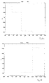
- Such height contours are shown by way of example in FIGS. 3a and 3b for data from the laser scanners 14 and 16, respectively, the origin of the coordinate system being chosen at any but fixed point.
- an x coordinate is calculated for each data point, which results from the time t i (14) or t i (16) or the corresponding time stamps of the scanning multiplied by the conveying speed of the conveyor belt 10 and the position of the scanning plane or Indicates the capture level at the time of capture.
- the total scan is successively based on the row of data points the previous scan of the laser scanner 14 in its original Order built up. At the beginning there is the total scan So only from the series of previously recorded data points in your original order.
- a subsequent step S16 the z coordinates of the data points the total scan then filtering with a median filter subject to three consecutive values become.
- Az coordinate a middle of three in the row of data points the total scan of successive data points is replaced by the z coordinate of the three data points, which are neither the smallest is still the largest of the three z coordinates.
- the result of Filtering is shown by way of example in FIG. 5. The solid line connects the filtered data points, while the individual points the unfiltered Show data points.
- a next step S18 the position of flanks which are essentially perpendicular to the carrier plane, ie which enclose an angle with the Z axis within a predetermined small angular range, is determined in the current total scan.
- differences in the z coordinates of successive filtered data points of the total scan referred to as height differences, are calculated and assigned to the data points.
- a subsequent step S20 the length and exact location are then of the edges found in the previous step is determined by the position of end points of the flanks is determined. For every found The following procedure is carried out on the flank (see FIG. 8):
- the mean value of the y coordinates becomes the y coordinate of the end points of the flank of all data points found.
- the search interval 38 indicated by horizontal lines Width lies in the middle of which the determined provisional value for z coordinate lies.
- the width of the search interval 38 in Dependence on the spatial resolution of the laser scanner 14 and 16 and the expected ranges of dimensions of the objects 20, 20 'and 20 "selected.
- the set of data points found then corresponds to one of the Flank orthogonal surface of the object.
- the x coordinate is the x coordinate of the end points of the flank of the data point defining the preliminary position of the edge used.
- an edge direction is assigned to an end point of a flank, referred to in the example as "left" and "right” edge direction becomes.
- This direction of the edge corresponds to the direction in which one is towards the flank orthogonal surface of the object in the corresponding End point connects to the flank. To do this, it is checked whether within of the search interval for the z direction, more data points are found, whose y coordinate has a smaller value than the y coordinate of the end point, or more data points, whose y coordinate has a larger value. In the first case, the end point is called the edge direction "left", otherwise "right” assigned.
- the result of the edge determination are thus calculated end points with newly determined x, y and z coordinates and assigned edge directions. These end points are represented in FIG. 8 by circles 34 and 34 '.
- the objects are essentially horizontal, i.e. in the X-Y plane Play edges or in individual cases a corner of the object.
- a subsequent step S22 the data on the Flanks, i.e. their end points and the edge directions assigned to them, in the current total scan and a given one Number of previous total scans for the level of the conveyor belt 10 parallel edges determined, the following as horizontal edges be designated. These horizontal edges give in a certain Meaning a floor plan of the captured objects again.
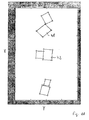
- Fig. 9 Projections of found end points of flanks on the X-Y plane are shown.
- the end point is searched for in the edge buffer, which is the largest Has the value of the x coordinate, that is the latest end point. With appropriate This is the arrangement of the end points in the edge buffer last end point.
- This path is the difference between the maximum x coordinates of the current one Endpoints and the x coordinate in the edge buffer with the largest The value of the x coordinate can be determined.
- This catch area corresponds in the X-Y plane like a triangle opening in the X direction.
- one becomes approximate slope of the edge in the X-Y plane is determined by a Sum of all differences of the y-coordinates of successive end points in the edge buffer by the sum of all differences of the x coordinates successive end points in the edge buffer divided becomes.
- a catch area is again in defines y-direction, the center of which is the expected value of the y-coordinate forms and the total width of which is twice that of the conveyor belt 10 path covered during a sampling period.
- the end point is placed in the edge buffer added.
- edge buffer is checked how many total scans no new End point has been included in the edge buffer, i.e. about which Distance in the X direction no end point was found. were over a predetermined number of total scans which correspond to a predetermined depending on the resolution of the laser scanner 14 and 16, the conveyor speed and an expected range of dimensions of objects 20, 20 'and 20 "selected route , no endpoints were found, it is assumed that the Edge is complete. The edge buffer is then closed and at the further edge search is no longer used.
- edge buffer less than a given one, depending of the resolving power and the expected range of dimensions the number of endpoints selected for the objects, five in the example, the preliminary edge and the edge buffer are discarded.
- the end points in the edge buffer from one through it regression line checks whether the constructed edge as Is to look straight. If this is not the case, the edge and the Edge buffer discarded.
- a start and an end point of the now complete Edge calculated by ending the end point in the edge buffer with the smallest value of the x coordinate on the regression line through the Endpoints in the edge buffer in a direction orthogonal to that Regression line is projected.
- the projected points are considered the end points of the edge, which is also the mean of the z coordinates of the end points as the z coordinate and the direction of the end points as the direction is assigned.
- End points of the current scan can be remaining as not assigned. It is then believed that this Endpoints each belong to a new edge and they are each new edge buffers opened.
- FIG. 10 The result of the edge formation based on FIG. 9 is shown in FIG. 10.
- step S24 the object detection is based on the previously performed as a fully identified horizontal edge.
- angles are first calculated that the horizontal found Include edges with the X axis.
- a first horizontal edge is determined from the set horizontal edges as the current edge. For the current edge then further edges in the predetermined amount of the horizontal Edges searched that are parallel to the current horizontal edge run, for which the previously determined angle with the X axis is used becomes. Parallelism is recognized when the angles are less than one differentiate the predetermined maximum value, in the example of about 2 °.
- edges that meet this criterion then become the edges selected whose z-coordinate is less than a predetermined maximum small z tolerance from the z coordinate of the current horizontal edge deviates and which one to the direction of the current horizontal Edge is assigned in the opposite direction.
- the edge is selected as the edge associated with the current edge, starting from the current edge in the direction indicated by the the direction assigned to the current edge is given. That means for example, that a current edge with direction "right” only one Edge with direction "left” is assigned, its end points in the y direction to the right of the end points of the current edge, i.e. larger y values exhibit. If several edges also meet this criterion, the Edge with the smallest distance selected.
- Edges can be calculated multiple times. Should be looking after an edge, an edge with a distance below a distance limit, which among other things by the minimum size of the finding objects and is less than 2 mm in the example, are found, this edge is deleted as redundant and further Procedure no longer used.
- the horizontal current edge and the associated parallel horizontal Edges are then marked as belonging to an object and made out the set of horizontal edges.
- the quantity of the determined horizontal edges orthogonal to the current horizontal edge Edges determined. It is checked for each of the edges in the set whether a deviation between their angle with the X axis and the angle the current horizontal edge and the X-axis modulo 180 ° within a predetermined error range of about 3 ° in the example. Is this the case, the horizontal edge is considered to be the current horizontal Edge viewed orthogonally.
- edges are then selected from the orthogonal edges, whose z coordinate is less than a predetermined maximum small Amount deviates from the z coordinate of the current horizontal edge.
- the next respective distances of the end points of the orthogonal horizontal edges from the endpoints of the current horizontal Edge and the end points of the parallel horizontal edge are these smaller than one depending on the minimum dimensions the object's predetermined error value, here about 50 mm, becomes one Orthogonal horizontal edge recognized as belonging to the object and off the set of horizontal edges.
- the object is only recognized as a new object if it is compared with already recognized objects has shown that it does not match them.
- the volume of the object or the object represented by it is then obtained by multiplying the base area by the Distance of the horizontal edges from the conveyor belt 10.
- the remaining set of horizontal edges then becomes one new current horizontal edge selected and the object determination repeated.
- the result of the object formation is shown in FIG. 11.
- the location data and the calculated volumes of the objects found on the corresponding Interface of the evaluation device 18 output and the other New data is read in via the input interfaces Evaluation were recorded during a new scan.
Landscapes
- Physics & Mathematics (AREA)
- General Physics & Mathematics (AREA)
- Length Measuring Devices With Unspecified Measuring Means (AREA)
- Length Measuring Devices By Optical Means (AREA)
- Control Of Conveyors (AREA)
- Container, Conveyance, Adherence, Positioning, Of Wafer (AREA)
- Die Bonding (AREA)
Abstract
Description
- Fig. 1
- eine schematische perspektivische Ansicht eines Förderbands mit Gegenständen und einer Vorrichtung zur Erfassung der Gegenstände,
- Fig. 2
- ein Ablaufdiagramm, in dem die Hauptschritte eines von der Vorrichtung in Fig. 1 verwendeten Verfahrens veranschaulicht sind,
- Fig. 3a,b
- zwei schematische Diagramme, in denen die Lage von von jeweils einem der Laserscanner in Fig. 1 erfassten Gegenstandspunkten in einer Y-Z-Ebene veranschaulicht sind,
- Fig. 4
- ein schematisches Diagramm, in dem die Daten in Fig. 3a, b nach einer Zusammenführung veranschaulicht sind,
- Fig. 5
- ein schematisches Diagramm, in dem die Daten aus Fig. 4 nach einer Filterung gezeigt sind,
- Fig. 6
- ein schematisches Diagramm, in dem den Datenpunkten in Fig. 5 zugeordnete Höhendifferenzen als Funktion der y-Koordinate der Datenpunkte aufgetragen sind,
- Fig. 7
- das schematisches Diagramm der Fig. 5, in dem die vorläufigen Lagen von Flanken definierenden Datenpunkten eingezeichnet sind,
- Fig. 8
- das schematische Diagramm der Fig. 5, in dem Suchbereiche zur Berechnung von Endpunkten einer Flanke eingezeichnet sind,
- Fig. 9
- ein schematisches Diagramm, in dem Projektionen von Endpunkten von gefundenen Flanken in die X-Y-Ebene dargestellt sind,
- Fig. 10
- das schematische Diagramm der Fig. 9 nach Ersetzung der Projektionen der Endpunkte durch horizontale Kanten, und
- Fig. 11
- das schematische Diagramm der Fig. 10 nach Konstruktion von Objekten.
- 10
- Förderband
- 12
- Brücke
- 14
- Laserscanner
- 16
- Laserscanner
- 18
- Auswerteeinrichtung
- 20, 20', 20"
- Gegenstände
- 22
- Strahlungsbündel
- 24
- Erfassungsbereich
- 26
- Abtastebene
- 28
- Bereich
- 30
- Erfassungsbereich
- 32, 32', 32"
- definierende Datenpunkte
- 34, 34'
- Endpunkte
- 36
- Suchintervall
- 38
- Suchintervall
- 40, 40'
- Kanten
- 42
- Objekt
- 44, 44'
- Kanten
- 46, 46'
- Kanten
- 48
- Objekt
- r
- Abstand
- ϕ
- Winkel
- F
- Förderrichtung
Claims (25)
- Verfahren zum Auffinden von Gegenständen (20, 20', 20") mit einer Standfläche eines vorgegebenen Flächentyps, einer zu der Standfläche im Wesentlichen parallelen Deckfläche und einer oder mehreren zu der Standfläche im Wesentlichen orthogonal verlaufenden Seitenflächen, insbesondere von quaderförmigen Gegenständen (20, 20', 20"), auf einer Trägerebene (10) auf der Basis von Daten, die durch eine in einer zu der Trägerebene (10) parallelen Förderrichtung (F) verlaufende Relativbewegung zwischen einer Abtastebene (26), die einen vorgegebenen Winkel mit der Trägerebene (10) einschließt, und den Gegenständen (20, 20', 20") und durch wiederholte Durchführung einer Gesamtabtastung der Lage von Punkten (28) auf den Gegenständen (20, 20', 20") innerhalb eines Erfassungsbereichs (24, 30) in der Abtastebene (26) erhalten wurden und die Informationen über die Lage der erfassten Gegenstandspunkte (28) in der Abtastebene (26) enthalten, sowie auf der Basis von Informationen, aus denen die Relativlage von Abtastebene (26) und Gegenständen (20, 20', 20") in Förderrichtung (F) während einer Gesamtabtastung ableitbar ist, bei dem wiederholt die Schritte ausgeführt werden: Einlesen der Daten über die Lage der Gegenstandspunkte (28) auf den Gegenständen (20, 20', 20") in der Abtastebene (26) und Erfassung von Informationen über die Relativlage von Abtastebene (26) und Gegenständen (20, 20', 20") in Förderrichtung (F) für eine aktuelle Gesamtabtastung,
Ermittlung von Lagen und Ausdehnungen von Flanken der Gegenstände, die mit der Trägerebene (10) im Wesentlichen einen rechten Winkel bilden, aus den Daten der aktuellen Gesamtabtastung, Ermittlung von Lagen und Längen von zu der Trägerebene (10) im Wesentlichen parallelen Kanten (40, 40', 44, 44', 46, 46') der Gegenstände (20, 20', 20") auf der Basis der Lagen und Ausdehnungen der Flanken sowie der Informationen über die Relativlage von Abtastebene (26) und Gegenständen (20, 20', 20") in Förderrichtung (F) in der aktuellen Gesamtabtastung und vorhergehenden Gesamtabtastungen, und
Bestimmung von Gegenständen (20, 20', 20") entsprechenden Objekten (42, 48) aus den Lagen und Längen der zu der Trägerebene (10) parallelen Kanten (40, 40', 44, 44', 46, 46'). - Verfahren nach Anspruch 1,
dadurch gekennzeichnet, dass Daten verwendet werden, die unter Verwendung einer zu der Trägerebene (10) orthogonalen Abtastebene (26) erhalten wurden. - Verfahren nach Anspruch 1 oder 2,
dadurch gekennzeichnet, dass vor der Bestimmung der Flanken die Daten in Bezug auf eine Richtung orthogonal zu der Trägerebene einer räumlichen Filterung unterzogen werden. - Verfahren nach einem der vorhergehenden Ansprüche,
dadurch gekennzeichnet, dass zur Erkennung der Flanken jeweils Beträge von Abständen von aufeinanderfolgenden Datenpunkten in einer Richtung orthogonal zu der Trägerebene (10) verwendet werden. - Verfahren nach einem der vorhergehenden Ansprüche,
dadurch gekennzeichnet, dass Lagen von Endpunkten (34, 34') der Flanken jeweils in einer Richtung parallel zu einer Schnittgeraden von Trägerebene (10) und Abtastebene (26) durch Mittelung entsprechender Daten von der Flanke zugeordneten Datenpunkten erhalten werden. - Verfahren nach einem der vorhergehenden Ansprüche,
dadurch gekennzeichnet, dass einem Endpunkt (34, 34') einer Flanke ein Abstand von der Trägerebene (10) oder ein Wert einer Koordinate in einer Richtung orthogonal zu der Trägerebene (10) zugeordnet wird, der durch Mittelung entsprechender Daten von Datenpunkten einer sich an die Flanke an dem Endpunkt (34, 34') anschließenden, zu der Flanke im Wesentlichen orthogonale Fläche eines erfassten Gegenstands (20, 20', 20") erhalten werden. - Verfahren nach einem der vorhergehenden Ansprüche,
dadurch gekennzeichnet, dass einem Endpunkt (34, 34') einer Flanke eine Richtung zugeordnet wird, die angibt, in welcher Richtung sich eine sich an die Flanke anschließende, zu dieser im Wesentlichen orthogonale Fläche eines erfassten Gegenstands (20, 20', 20") erstreckt. - Verfahren nach einem der vorhergehenden Ansprüche,
dadurch gekennzeichnet, dass die Lage von Endpunkten (34, 34') der Flanken einer Gesamtabtastung in der Förderrichtung (F) der Gegenstände auf der Basis der Bewegungsgeschwindigkeit zwischen der Abtastebene (26) und den Gegenständen (20, 20', 20") und dem zeitlichen Abstand der Gesamtabtastung von der aktuellen Gesamtabtastung bestimmt wird. - Verfahren nach einem der vorhergehenden Ansprüche,
dadurch gekennzeichnet, dass bei der Bestimmung der zu der Trägerebene (10) parallelen Kanten (40, 40', 44, 44', 46, 46') die Lagen von Endpunkten (34, 34') der Flanken und die den Endpunkten (34, 34') zugeordneten Richtungen verwendet werden. - Verfahren nach einem der vorhergehenden Ansprüche,
dadurch gekennzeichnet, dass es zur Auffindung von quaderförmigen Gegenständen (20, 20', 20") verwendet wird, und
dass ein neues Objekt (42, 48) nur dann erzeugt wird, wenn zwei zu der Trägerebene (10) im Wesentlichen parallele Kanten (40, 40', 44, 44', 46, 46') aufgefunden werden, die in etwa den gleichen Abstand von der Trägerebene (10) aufweisen und einen Winkel einschließen, dessen Betrag kleiner als ein vorgegebener Grenzwinkel ist. - Verfahren nach Anspruch 10,
dadurch gekennzeichnet, dass es zur Auffindung von quaderförmigen Gegenständen (20, 20', 20") verwendet wird, und
dass ein neues Objekt (42, 48) nur dann erzeugt wird, wenn den Endpunkten (34, 34'), die der einen zu der Trägerebene (10) parallelen Kante zugrunde liegen, eine andere Richtung zugeordnet ist, als den Endpunkten (34, 34'), die der anderen zu der Trägerebene (10) parallelen Kante zugrunde liegen. - Verfahren nach einem der vorhergehenden Ansprüche,
dadurch gekennzeichnet, dass das Volumen wenigstens eines Objekts (42, 48) auf der Basis einer Grundfläche, die durch zu der Trägerebene (10) parallele Kanten (40, 40', 44, 44', 46, 46') des Objekts (42, 48) gegeben ist, und des Abstandes der zu der Trägerebene (10) parallelen Kanten (40, 40', 44, 44', 46, 46') von der Trägerebene (10) berechnet wird. - Verfahren zur Erfassung von Gegenständen (20, 20', 20") mit einer Standfläche eines vorgegebenen Flächentyps, einer zu der Standfläche im Wesentlichen parallelen Deckfläche und einer oder mehreren zu der Standfläche im Wesentlichen orthogonal verlaufenden Seitenflächen, insbesondere von quaderförmigen Gegenständen (20, 20', 20"), auf einer Trägerebene (10), bei dem
eine Abtastebene (26), die im Wesentlichen einen vorgegebenen Winkel mit der Trägerebene (10) einschließt, und die Gegenstände in einer zu der Trägerebene (10) parallelen Förderrichtung (F) relativ zueinander bewegt werden,
dabei wiederholt eine Gesamtabtastung eines Erfassungsbereichs (24, 30) in der Abtastebene (26) durchgeführt wird, bei der Daten über die Lage von Gegenstandspunkten (28) auf den Gegenständen (20, 20', 20") in der Abtastebene (26) sowie Informationen, aus denen die Relativlage von Abtastebene (26) und Gegenständen (20, 20', 20") in Förderrichtung (F) während einer Gesamtabtastung ableitbar ist, erfasst werden, und
das Verfahren nach einem der Ansprüche 1 bis 12 auf der Basis der gewonnenen Daten durchgeführt wird. - Verfahren nach Anspruch 13,
dadurch gekennzeichnet, dass die Abtastebene (26) im Wesentlichen orthogonal zu der Trägerebene (10) ausgerichtet ist. - Verfahren nach Anspruch 13 oder 14,
dadurch gekennzeichnet, dass die Daten über die Lage von Gegenstandspunkten (28) mittels einer Lasermesseinrichtung (14, 16) erfasst werden, die einen flächigen Erfassungsbereich (24, 30) aufweist. - Verfahren nach einem der Ansprüche 13 bis 15,
dass eine Lasermesseinrichtung (14, 16) verwendet wird, die wenigstens einen Laserscanner, vorzugsweise einen Radialscanner (14, 16), umfasst. - Verfahren nach einem der Ansprüche 13 bis 16,
dadurch gekennzeichnet, dass wenigstens zwei, in Förderrichtung (F) der Gegenstände und oberhalb der Trägerebene (10) angeordnete Laserscanner, insbesondere Radialscanner (14, 16), verwendet werden, deren Erfassungsbereiche (24, 30) sich überlappen. - Verfahren nach einem der Ansprüche 13 bis 17,
dadurch gekennzeichnet, dass bei ortsfest angeordneter Abtastebene (26) die Gegenstände (20, 20', 20") bewegt werden. - Vorrichtung zur Erfassung von mit einer Standfläche eines vorgegebenen Flächentyps, einer zu der Standfläche im Wesentlichen parallelen Deckfläche und einer oder mehreren zu der Standfläche im Wesentlichen orthogonal verlaufenden Seitenflächen, insbesondere von quaderförmigen Gegenständen (20, 20', 20"), auf einer Trägerebene (10) mit mindestens einem Sensor (14, 16) für elektromagnetische Strahlung, mit dem bei wiederholten Gesamtabtastungen Daten in Bezug auf die Lage von Punkten auf den Gegenständen
(20, 20', 20") in einem Erfassungsbereich (24, 30) in einer Abtastebene (26) des Sensors (14, 16) erfassbar sind,
einer Einrichtung (10), mit der die Gegenstände (20, 20', 20") und der Sensor (14, 16) in einer zu der Trägerebene (10) parallelen Förderrichtung (F) relativ zueinander bewegbar sind,
wobei die Abtastebene (26) des Sensors (14, 16) einen vorgegebenen Winkel mit der Trägerebene (10) einschließt ist, und
mit einer Datenverarbeitungseinrichtung (18), die zur Durchführung des Verfahrens nach einem der Ansprüche 1 bis 12 ausgebildet ist. - Vorrichtung nach Anspruch 19,
dadurch gekennzeichnet, dass die Abtastebene (26) im Wesentlichen orthogonal zu der Trägerebene (10) ausgerichtet ist. - Vorrichtung nach Anspruch 19 oder 20,
dadurch gekennzeichnet, dass der Sensor (14, 16) ein Laserscanner, insbesondere ein Radialscanner, ist. - Vorrichtung nach Anspruch 21,
dadurch gekennzeichnet, dass zwei Laserscanner (14, 16) vorgesehen sind, deren Abtastebenen (26) in einem vorgegebenen Winkel zu der Trägerebene (10) geneigt sind und in einem vorgegebenen Abstand von dieser entfernt und zu beiden Seiten einer möglichen Bewegungsbahn der Gegenstände (20, 20', 20") angeordnet sind. - Vorrichtung nach einem der Ansprüche 19 bis 22,
dadurch gekennzeichnet, dass die Einrichtung (10) zur Relativbewegung eine Fördereinrichtung (10) für die Gegenstände (20, 20', 20") ist. - Computerprogramm mit Programmcode-Mitteln, um die Verfahren nach einem der Ansprüche 1 bis 12 durchzuführen, wenn das Programm auf einem Computer ausgeführt wird.
- Computerprogrammprodukt mit Programmcode-Mitteln, die auf einem computerlesbaren Datenträger gespeichert sind, um das Verfahren nach einem der Ansprüche 1 bis 12 durchzuführen, wenn das Computerprogrammprodukt auf einem Computer ausgeführt wird.
Applications Claiming Priority (2)
| Application Number | Priority Date | Filing Date | Title |
|---|---|---|---|
| DE10226663 | 2002-06-14 | ||
| DE10226663A DE10226663A1 (de) | 2002-06-14 | 2002-06-14 | Verfahren zum Auffinden von Gegenständen auf einer Trägerebene |
Publications (2)
| Publication Number | Publication Date |
|---|---|
| EP1371940A1 true EP1371940A1 (de) | 2003-12-17 |
| EP1371940B1 EP1371940B1 (de) | 2005-10-26 |
Family
ID=29557836
Family Applications (1)
| Application Number | Title | Priority Date | Filing Date |
|---|---|---|---|
| EP03011367A Expired - Lifetime EP1371940B1 (de) | 2002-06-14 | 2003-05-19 | Verfahren zum Auffinden von Gegenständen auf einer Trägerebene |
Country Status (6)
| Country | Link |
|---|---|
| US (1) | US6847859B2 (de) |
| EP (1) | EP1371940B1 (de) |
| AT (1) | ATE308026T1 (de) |
| DE (2) | DE10226663A1 (de) |
| DK (1) | DK1371940T3 (de) |
| ES (1) | ES2250782T3 (de) |
Cited By (2)
| Publication number | Priority date | Publication date | Assignee | Title |
|---|---|---|---|---|
| WO2008022977A1 (de) * | 2006-08-23 | 2008-02-28 | Kratzmaier Konstruktionen Gmbh | Be- und entladen von fluggepäckstücken |
| EP1945416A4 (de) * | 2005-10-18 | 2011-02-16 | Binar Aktiebolag | Verfahren und anordnung zur suche und entnahme von objekten auf einem träger |
Families Citing this family (22)
| Publication number | Priority date | Publication date | Assignee | Title |
|---|---|---|---|---|
| DE10252901A1 (de) * | 2002-11-12 | 2004-05-27 | Siemens Ag | Verfahren und System zum Materialtransport |
| DE10336493A1 (de) * | 2003-08-08 | 2005-03-03 | Byk-Gardner Gmbh | Vorrichtung und Verfahren zur Bestimmung von Oberflächeneigenschaften |
| JP4064361B2 (ja) * | 2004-03-15 | 2008-03-19 | 川崎重工業株式会社 | 搬送装置の搬送位置の位置情報取得方法 |
| DE102005043223B4 (de) * | 2005-09-09 | 2008-05-21 | Rattunde & Co Gmbh | Messstation für eine Rohrschneidemaschine |
| DE102005054658A1 (de) * | 2005-11-16 | 2007-05-24 | Sick Ag | Verfahren zur automatischen Paramentierung von Meßsystemen |
| ES2348858T3 (es) | 2006-04-27 | 2010-12-03 | Sick Ag | Procedimiento y dispositivo de escaneado. |
| US8467898B2 (en) * | 2007-03-08 | 2013-06-18 | Smv S.R.L. | Method and a device for recognizing, collecting and repositioning objects |
| US20090095047A1 (en) * | 2007-10-16 | 2009-04-16 | Mehul Patel | Dimensioning and barcode reading system |
| US9201163B2 (en) * | 2013-06-07 | 2015-12-01 | Intelligrated Headquarters, Llc | Dual laser article detection system |
| CN205274562U (zh) * | 2016-01-04 | 2016-06-01 | 合肥鑫晟光电科技有限公司 | 一种传送装置 |
| EP3203180B1 (de) * | 2016-02-04 | 2018-12-05 | Mettler-Toledo GmbH | Vorrichtung und verfahren zur dimensionierung eines objekts, das von einem fahrzeug getragen wird, das sich in einem messfeld bewegt |
| DE102016124400A1 (de) * | 2016-12-14 | 2018-06-14 | Krones Ag | Verfahren und Vorrichtung zum Erfassen von Störungen beim Objekttransport |
| US10656276B2 (en) * | 2017-07-29 | 2020-05-19 | Verizon Patent And Licensing Inc. | Systems and methods for inward-looking depth scanning of a scan zone |
| CN107348616A (zh) * | 2017-08-22 | 2017-11-17 | 武汉维码科技有限公司 | 一种三维双足扫描仪 |
| LU100782B1 (en) * | 2018-04-27 | 2019-10-28 | Soremartec Sa | System for conveying products in succession along an industrial line |
| CN108629325B (zh) * | 2018-05-11 | 2021-06-22 | 北京旷视科技有限公司 | 物品位置的确定方法、装置及系统 |
| CN108981842B (zh) * | 2018-08-17 | 2019-12-24 | 湖北凯瑞知行智能装备有限公司 | 基于激光线性光源辅助的胶带物料堆形体积计算及偏载和堵料识别方法 |
| CN109230351B (zh) * | 2018-08-30 | 2020-06-16 | 精英数智科技股份有限公司 | 一种皮带输送机运行异常的识别方法 |
| US10625952B1 (en) * | 2019-10-18 | 2020-04-21 | Grey Orange Pte. Ltd. | Induction station for conveying packages in storage facility |
| DE102020211394A1 (de) | 2020-09-10 | 2022-03-10 | Volkswagen Aktiengesellschaft | Vorrichtung und Verfahren zur Positionsbestimmung eines Werkstücks |
| US11995879B2 (en) | 2021-07-29 | 2024-05-28 | Datalogic Usa, Inc. | Image processing for separation of adjacent objects |
| CN115475267B (zh) * | 2022-09-19 | 2023-12-01 | 上海莱陆科技有限公司 | 一种物表消毒设备的智能控制系统 |
Citations (5)
| Publication number | Priority date | Publication date | Assignee | Title |
|---|---|---|---|---|
| EP0374799A2 (de) * | 1988-12-22 | 1990-06-27 | Kabushiki Kaisha Toshiba | Gerät zum Detektieren einer Anzahl Packungen in einem Bündel |
| EP0501639A2 (de) * | 1991-02-28 | 1992-09-02 | Kirby Lester, Inc. | Gerät und Verfahren zum Zählen von Gegenständen |
| US5412420A (en) * | 1992-10-26 | 1995-05-02 | Pheno Imaging, Inc. | Three-dimensional phenotypic measuring system for animals |
| EP0690287A2 (de) * | 1994-07-01 | 1996-01-03 | Siemens Aktiengesellschaft | Verfahren zum Vermessen von quaderförmigen Gegenständen und Einrichtung zur Durchführung des Verfahrens |
| EP0851208A1 (de) * | 1996-12-31 | 1998-07-01 | Datalogic S.P.A. | Verfahren zur Volumenmessung eines Gegenstandes mittels eines Laserabtasters und Apparat zum Ausführen dieses Verfahrens |
Family Cites Families (10)
| Publication number | Priority date | Publication date | Assignee | Title |
|---|---|---|---|---|
| US5501571A (en) * | 1993-01-21 | 1996-03-26 | International Business Machines Corporation | Automated palletizing system |
| JP2692603B2 (ja) * | 1994-07-13 | 1997-12-17 | 村田機械株式会社 | 三次元計測方法 |
| US5661561A (en) * | 1995-06-02 | 1997-08-26 | Accu-Sort Systems, Inc. | Dimensioning system |
| US5699161A (en) * | 1995-07-26 | 1997-12-16 | Psc, Inc. | Method and apparatus for measuring dimensions of objects on a conveyor |
| US6554189B1 (en) * | 1996-10-07 | 2003-04-29 | Metrologic Instruments, Inc. | Automated system and method for identifying and measuring packages transported through a laser scanning tunnel |
| US6064759A (en) * | 1996-11-08 | 2000-05-16 | Buckley; B. Shawn | Computer aided inspection machine |
| ATE247273T1 (de) | 1996-12-31 | 2003-08-15 | Datalogic Spa | Verfahren und apparat zur volumenmessung eines gegenstandes mittels eines laserabtasters |
| ATE268464T1 (de) * | 1996-12-31 | 2004-06-15 | Datalogic Spa | Verfahren und apparat zur volumenmessung eines gegenstandes |
| DE19741731A1 (de) | 1997-09-22 | 1999-04-01 | Sick Ag | Vorrichtung zur optischen Abtastung von Oberflächen |
| DE19741730B4 (de) | 1997-09-22 | 2006-02-02 | Sick Ag | Verfahren zur Ermittlung der Oberflächenkontur von Meßobjekten |
-
2002
- 2002-06-14 DE DE10226663A patent/DE10226663A1/de not_active Withdrawn
- 2002-09-17 US US10/245,599 patent/US6847859B2/en not_active Expired - Lifetime
-
2003
- 2003-05-19 AT AT03011367T patent/ATE308026T1/de active
- 2003-05-19 DE DE50301458T patent/DE50301458D1/de not_active Expired - Lifetime
- 2003-05-19 ES ES03011367T patent/ES2250782T3/es not_active Expired - Lifetime
- 2003-05-19 DK DK03011367T patent/DK1371940T3/da active
- 2003-05-19 EP EP03011367A patent/EP1371940B1/de not_active Expired - Lifetime
Patent Citations (5)
| Publication number | Priority date | Publication date | Assignee | Title |
|---|---|---|---|---|
| EP0374799A2 (de) * | 1988-12-22 | 1990-06-27 | Kabushiki Kaisha Toshiba | Gerät zum Detektieren einer Anzahl Packungen in einem Bündel |
| EP0501639A2 (de) * | 1991-02-28 | 1992-09-02 | Kirby Lester, Inc. | Gerät und Verfahren zum Zählen von Gegenständen |
| US5412420A (en) * | 1992-10-26 | 1995-05-02 | Pheno Imaging, Inc. | Three-dimensional phenotypic measuring system for animals |
| EP0690287A2 (de) * | 1994-07-01 | 1996-01-03 | Siemens Aktiengesellschaft | Verfahren zum Vermessen von quaderförmigen Gegenständen und Einrichtung zur Durchführung des Verfahrens |
| EP0851208A1 (de) * | 1996-12-31 | 1998-07-01 | Datalogic S.P.A. | Verfahren zur Volumenmessung eines Gegenstandes mittels eines Laserabtasters und Apparat zum Ausführen dieses Verfahrens |
Cited By (2)
| Publication number | Priority date | Publication date | Assignee | Title |
|---|---|---|---|---|
| EP1945416A4 (de) * | 2005-10-18 | 2011-02-16 | Binar Aktiebolag | Verfahren und anordnung zur suche und entnahme von objekten auf einem träger |
| WO2008022977A1 (de) * | 2006-08-23 | 2008-02-28 | Kratzmaier Konstruktionen Gmbh | Be- und entladen von fluggepäckstücken |
Also Published As
| Publication number | Publication date |
|---|---|
| DK1371940T3 (da) | 2005-12-05 |
| US6847859B2 (en) | 2005-01-25 |
| ES2250782T3 (es) | 2006-04-16 |
| ATE308026T1 (de) | 2005-11-15 |
| DE50301458D1 (de) | 2005-12-01 |
| DE10226663A1 (de) | 2003-12-24 |
| US20030233166A1 (en) | 2003-12-18 |
| EP1371940B1 (de) | 2005-10-26 |
Similar Documents
| Publication | Publication Date | Title |
|---|---|---|
| EP1371940B1 (de) | Verfahren zum Auffinden von Gegenständen auf einer Trägerebene | |
| DE3854348T2 (de) | Verfahren und Vorrichtung zum Messen der Form einer dreidimensional gekrümmten Oberfläche. | |
| DE69625423T2 (de) | Vorrichtung zur Erkennung eines Objektes, in welchem die Position eines ebenen Objektes mit Hilfe einer Houghtransformation geschätzt wird | |
| EP2417561B1 (de) | Zweidimensionaler symbolcode und verfahren zum lesen des symbolcodes | |
| DE69306399T2 (de) | Validierung der optischen Entfernungsmessung einer Zieloberfläche in einer gestörten Umgebung | |
| DE69723213T2 (de) | System zum Messen des Spiels und der Koplanarität zweier nebeneinander liegender Objekte | |
| WO2004055548A1 (de) | Verfahren zur erkennung und verfolgung von objekten | |
| EP2439487A1 (de) | Volumenmessvorrichtung für bewegte Objekte | |
| DE19805794A1 (de) | Schnelle planare Segmentierung von Entfernungsdaten für mobile Roboter | |
| DE102016116572A1 (de) | Ausrichtung von Punktwolken zur Modellierung von Innenräumen | |
| DE102020120887B4 (de) | Verfahren zum erfassen einer einhängeposition eines auflagestegs und flachbettwerkzeugmaschine | |
| EP1788347B1 (de) | Verfahren zur automatischen Parametrierung von Messsystemen | |
| DE102018123393A1 (de) | Erkennung von Parkflächen | |
| DE102015121673A1 (de) | Formermittlungsverfahren | |
| EP1098268A2 (de) | Verfahren zur dreidimensionalen optischen Vermessung von Objektoberflächen | |
| DE69326920T2 (de) | Verfahren zum prüfen von artikeln | |
| DE19632058C1 (de) | Optoelektronisch erfaßbares Identifizierungs- oder Zielelement sowie Verfahren zu seiner Erfassung | |
| WO2024208566A1 (de) | Verfahren zur ermittlung von mindestens einem freiheitsgrad einer kamera, computerprogramm, maschinenlesbares speichermedium und elektronische steuereinheit oder automatisierungsanordnung | |
| DE102008020579A1 (de) | Verfahren zur automatischen Objektlageerkennung und Bewegung einer Vorrichtung relativ zu einem Objekt | |
| DE202014101714U1 (de) | Codelesesystem zum Lesen von Codes | |
| EP3985608B1 (de) | Computer-implementiertes verfahren zur erstellung von mehrdimensionalen gegenstands-datenstrukturen | |
| DE102021100138B4 (de) | Bilddatenprozessor, Sensoranordnung und computerimplementiertes Verfahren | |
| EP4368945B1 (de) | Sensoranordnung | |
| WO2019048205A1 (de) | Multikamerasystem für ein fahrzeug | |
| EP0508339B1 (de) | Messsystem zur berührungslosen Erfassung der Kontur von Langgegenständen mit diffus reflektierender Oberfläche |
Legal Events
| Date | Code | Title | Description |
|---|---|---|---|
| PUAI | Public reference made under article 153(3) epc to a published international application that has entered the european phase |
Free format text: ORIGINAL CODE: 0009012 |
|
| AK | Designated contracting states |
Kind code of ref document: A1 Designated state(s): AT BE BG CH CY CZ DE DK EE ES FI FR GB GR HU IE IT LI LU MC NL PT RO SE SI SK TR |
|
| AX | Request for extension of the european patent |
Extension state: AL LT LV MK |
|
| 17P | Request for examination filed |
Effective date: 20040205 |
|
| AKX | Designation fees paid |
Designated state(s): AT BE BG CH CY CZ DE DK EE ES FI FR GB GR HU IE IT LI LU MC NL PT RO SE SI SK TR |
|
| GRAP | Despatch of communication of intention to grant a patent |
Free format text: ORIGINAL CODE: EPIDOSNIGR1 |
|
| GRAS | Grant fee paid |
Free format text: ORIGINAL CODE: EPIDOSNIGR3 |
|
| GRAA | (expected) grant |
Free format text: ORIGINAL CODE: 0009210 |
|
| AK | Designated contracting states |
Kind code of ref document: B1 Designated state(s): AT BE BG CH CY CZ DE DK EE ES FI FR GB GR HU IE IT LI LU MC NL PT RO SE SI SK TR |
|
| PG25 | Lapsed in a contracting state [announced via postgrant information from national office to epo] |
Ref country code: IE Free format text: LAPSE BECAUSE OF FAILURE TO SUBMIT A TRANSLATION OF THE DESCRIPTION OR TO PAY THE FEE WITHIN THE PRESCRIBED TIME-LIMIT Effective date: 20051026 Ref country code: RO Free format text: LAPSE BECAUSE OF FAILURE TO SUBMIT A TRANSLATION OF THE DESCRIPTION OR TO PAY THE FEE WITHIN THE PRESCRIBED TIME-LIMIT Effective date: 20051026 Ref country code: SI Free format text: LAPSE BECAUSE OF FAILURE TO SUBMIT A TRANSLATION OF THE DESCRIPTION OR TO PAY THE FEE WITHIN THE PRESCRIBED TIME-LIMIT Effective date: 20051026 |
|
| REG | Reference to a national code |
Ref country code: GB Ref legal event code: FG4D Free format text: NOT ENGLISH |
|
| REG | Reference to a national code |
Ref country code: CH Ref legal event code: EP |
|
| REG | Reference to a national code |
Ref country code: IE Ref legal event code: FG4D Free format text: LANGUAGE OF EP DOCUMENT: GERMAN |
|
| REF | Corresponds to: |
Ref document number: 50301458 Country of ref document: DE Date of ref document: 20051201 Kind code of ref document: P |
|
| REG | Reference to a national code |
Ref country code: DK Ref legal event code: T3 |
|
| GBT | Gb: translation of ep patent filed (gb section 77(6)(a)/1977) |
Effective date: 20051214 |
|
| PG25 | Lapsed in a contracting state [announced via postgrant information from national office to epo] |
Ref country code: GR Free format text: LAPSE BECAUSE OF FAILURE TO SUBMIT A TRANSLATION OF THE DESCRIPTION OR TO PAY THE FEE WITHIN THE PRESCRIBED TIME-LIMIT Effective date: 20060126 Ref country code: BG Free format text: LAPSE BECAUSE OF FAILURE TO SUBMIT A TRANSLATION OF THE DESCRIPTION OR TO PAY THE FEE WITHIN THE PRESCRIBED TIME-LIMIT Effective date: 20060126 |
|
| REG | Reference to a national code |
Ref country code: HU Ref legal event code: AG4A Ref document number: E000136 Country of ref document: HU |
|
| REG | Reference to a national code |
Ref country code: SE Ref legal event code: TRGR |
|
| REG | Reference to a national code |
Ref country code: ES Ref legal event code: FG2A Ref document number: 2250782 Country of ref document: ES Kind code of ref document: T3 |
|
| REG | Reference to a national code |
Ref country code: IE Ref legal event code: FD4D |
|
| PG25 | Lapsed in a contracting state [announced via postgrant information from national office to epo] |
Ref country code: BE Free format text: LAPSE BECAUSE OF NON-PAYMENT OF DUE FEES Effective date: 20060531 Ref country code: MC Free format text: LAPSE BECAUSE OF NON-PAYMENT OF DUE FEES Effective date: 20060531 |
|
| ET | Fr: translation filed | ||
| PLBE | No opposition filed within time limit |
Free format text: ORIGINAL CODE: 0009261 |
|
| STAA | Information on the status of an ep patent application or granted ep patent |
Free format text: STATUS: NO OPPOSITION FILED WITHIN TIME LIMIT |
|
| 26N | No opposition filed |
Effective date: 20060727 |
|
| BERE | Be: lapsed |
Owner name: SICK A.G. Effective date: 20060531 |
|
| PG25 | Lapsed in a contracting state [announced via postgrant information from national office to epo] |
Ref country code: EE Free format text: LAPSE BECAUSE OF FAILURE TO SUBMIT A TRANSLATION OF THE DESCRIPTION OR TO PAY THE FEE WITHIN THE PRESCRIBED TIME-LIMIT Effective date: 20051026 |
|
| PG25 | Lapsed in a contracting state [announced via postgrant information from national office to epo] |
Ref country code: LU Free format text: LAPSE BECAUSE OF NON-PAYMENT OF DUE FEES Effective date: 20060519 Ref country code: TR Free format text: LAPSE BECAUSE OF FAILURE TO SUBMIT A TRANSLATION OF THE DESCRIPTION OR TO PAY THE FEE WITHIN THE PRESCRIBED TIME-LIMIT Effective date: 20051026 |
|
| PG25 | Lapsed in a contracting state [announced via postgrant information from national office to epo] |
Ref country code: CY Free format text: LAPSE BECAUSE OF FAILURE TO SUBMIT A TRANSLATION OF THE DESCRIPTION OR TO PAY THE FEE WITHIN THE PRESCRIBED TIME-LIMIT Effective date: 20051026 |
|
| PGFP | Annual fee paid to national office [announced via postgrant information from national office to epo] |
Ref country code: PT Payment date: 20110505 Year of fee payment: 9 Ref country code: CZ Payment date: 20110506 Year of fee payment: 9 |
|
| PGFP | Annual fee paid to national office [announced via postgrant information from national office to epo] |
Ref country code: FI Payment date: 20110520 Year of fee payment: 9 Ref country code: SK Payment date: 20110512 Year of fee payment: 9 Ref country code: HU Payment date: 20110512 Year of fee payment: 9 |
|
| REG | Reference to a national code |
Ref country code: PT Ref legal event code: MM4A Free format text: LAPSE DUE TO NON-PAYMENT OF FEES Effective date: 20121119 |
|
| PG25 | Lapsed in a contracting state [announced via postgrant information from national office to epo] |
Ref country code: SK Free format text: LAPSE BECAUSE OF NON-PAYMENT OF DUE FEES Effective date: 20120519 Ref country code: CZ Free format text: LAPSE BECAUSE OF NON-PAYMENT OF DUE FEES Effective date: 20120519 Ref country code: HU Free format text: LAPSE BECAUSE OF NON-PAYMENT OF DUE FEES Effective date: 20120520 Ref country code: FI Free format text: LAPSE BECAUSE OF NON-PAYMENT OF DUE FEES Effective date: 20120519 |
|
| REG | Reference to a national code |
Ref country code: SK Ref legal event code: MM4A Ref document number: E 290 Country of ref document: SK Effective date: 20120519 |
|
| PG25 | Lapsed in a contracting state [announced via postgrant information from national office to epo] |
Ref country code: PT Free format text: LAPSE BECAUSE OF NON-PAYMENT OF DUE FEES Effective date: 20121119 |
|
| PGFP | Annual fee paid to national office [announced via postgrant information from national office to epo] |
Ref country code: GB Payment date: 20140520 Year of fee payment: 12 |
|
| PGFP | Annual fee paid to national office [announced via postgrant information from national office to epo] |
Ref country code: NL Payment date: 20140520 Year of fee payment: 12 Ref country code: FR Payment date: 20140516 Year of fee payment: 12 Ref country code: AT Payment date: 20140519 Year of fee payment: 12 Ref country code: ES Payment date: 20140521 Year of fee payment: 12 Ref country code: CH Payment date: 20140522 Year of fee payment: 12 Ref country code: SE Payment date: 20140520 Year of fee payment: 12 |
|
| PGFP | Annual fee paid to national office [announced via postgrant information from national office to epo] |
Ref country code: DK Payment date: 20140521 Year of fee payment: 12 |
|
| REG | Reference to a national code |
Ref country code: DK Ref legal event code: EBP Effective date: 20150531 |
|
| REG | Reference to a national code |
Ref country code: CH Ref legal event code: PL |
|
| REG | Reference to a national code |
Ref country code: AT Ref legal event code: MM01 Ref document number: 308026 Country of ref document: AT Kind code of ref document: T Effective date: 20150519 |
|
| GBPC | Gb: european patent ceased through non-payment of renewal fee |
Effective date: 20150519 |
|
| PG25 | Lapsed in a contracting state [announced via postgrant information from national office to epo] |
Ref country code: LI Free format text: LAPSE BECAUSE OF NON-PAYMENT OF DUE FEES Effective date: 20150531 Ref country code: CH Free format text: LAPSE BECAUSE OF NON-PAYMENT OF DUE FEES Effective date: 20150531 |
|
| REG | Reference to a national code |
Ref country code: NL Ref legal event code: MM Effective date: 20150601 |
|
| REG | Reference to a national code |
Ref country code: FR Ref legal event code: ST Effective date: 20160129 |
|
| PG25 | Lapsed in a contracting state [announced via postgrant information from national office to epo] |
Ref country code: AT Free format text: LAPSE BECAUSE OF NON-PAYMENT OF DUE FEES Effective date: 20150519 Ref country code: SE Free format text: LAPSE BECAUSE OF NON-PAYMENT OF DUE FEES Effective date: 20150520 |
|
| PG25 | Lapsed in a contracting state [announced via postgrant information from national office to epo] |
Ref country code: NL Free format text: LAPSE BECAUSE OF NON-PAYMENT OF DUE FEES Effective date: 20150601 Ref country code: DK Free format text: LAPSE BECAUSE OF NON-PAYMENT OF DUE FEES Effective date: 20150531 Ref country code: GB Free format text: LAPSE BECAUSE OF NON-PAYMENT OF DUE FEES Effective date: 20150519 |
|
| PG25 | Lapsed in a contracting state [announced via postgrant information from national office to epo] |
Ref country code: FR Free format text: LAPSE BECAUSE OF NON-PAYMENT OF DUE FEES Effective date: 20150601 |
|
| REG | Reference to a national code |
Ref country code: ES Ref legal event code: FD2A Effective date: 20160701 |
|
| PG25 | Lapsed in a contracting state [announced via postgrant information from national office to epo] |
Ref country code: ES Free format text: LAPSE BECAUSE OF NON-PAYMENT OF DUE FEES Effective date: 20150520 |
|
| PGFP | Annual fee paid to national office [announced via postgrant information from national office to epo] |
Ref country code: DE Payment date: 20180524 Year of fee payment: 16 |
|
| PGFP | Annual fee paid to national office [announced via postgrant information from national office to epo] |
Ref country code: IT Payment date: 20180518 Year of fee payment: 16 |
|
| REG | Reference to a national code |
Ref country code: DE Ref legal event code: R119 Ref document number: 50301458 Country of ref document: DE |
|
| PG25 | Lapsed in a contracting state [announced via postgrant information from national office to epo] |
Ref country code: DE Free format text: LAPSE BECAUSE OF NON-PAYMENT OF DUE FEES Effective date: 20191203 Ref country code: IT Free format text: LAPSE BECAUSE OF NON-PAYMENT OF DUE FEES Effective date: 20190519 |