EP1371867A1 - Mitnehmerscheibe für Lamellenkupplungssysteme - Google Patents
Mitnehmerscheibe für Lamellenkupplungssysteme Download PDFInfo
- Publication number
- EP1371867A1 EP1371867A1 EP02013205A EP02013205A EP1371867A1 EP 1371867 A1 EP1371867 A1 EP 1371867A1 EP 02013205 A EP02013205 A EP 02013205A EP 02013205 A EP02013205 A EP 02013205A EP 1371867 A1 EP1371867 A1 EP 1371867A1
- Authority
- EP
- European Patent Office
- Prior art keywords
- tooth
- driving plate
- teeth
- plate
- driving
- Prior art date
- Legal status (The legal status is an assumption and is not a legal conclusion. Google has not performed a legal analysis and makes no representation as to the accuracy of the status listed.)
- Granted
Links
- 230000036316 preload Effects 0.000 claims description 8
- 238000003780 insertion Methods 0.000 claims description 6
- 230000037431 insertion Effects 0.000 claims description 6
- 230000002093 peripheral effect Effects 0.000 abstract description 3
- 238000010008 shearing Methods 0.000 abstract 1
- 239000002184 metal Substances 0.000 description 3
- 238000002485 combustion reaction Methods 0.000 description 2
- 230000000694 effects Effects 0.000 description 2
- 230000005284 excitation Effects 0.000 description 2
- 238000011161 development Methods 0.000 description 1
- 230000018109 developmental process Effects 0.000 description 1
- 238000006073 displacement reaction Methods 0.000 description 1
- 230000008030 elimination Effects 0.000 description 1
- 238000003379 elimination reaction Methods 0.000 description 1
- 230000006870 function Effects 0.000 description 1
- 238000004519 manufacturing process Methods 0.000 description 1
- 239000000725 suspension Substances 0.000 description 1
Images

Classifications
-
- F—MECHANICAL ENGINEERING; LIGHTING; HEATING; WEAPONS; BLASTING
- F16—ENGINEERING ELEMENTS AND UNITS; GENERAL MEASURES FOR PRODUCING AND MAINTAINING EFFECTIVE FUNCTIONING OF MACHINES OR INSTALLATIONS; THERMAL INSULATION IN GENERAL
- F16D—COUPLINGS FOR TRANSMITTING ROTATION; CLUTCHES; BRAKES
- F16D13/00—Friction clutches
- F16D13/58—Details
- F16D13/60—Clutching elements
- F16D13/64—Clutch-plates; Clutch-lamellae
- F16D13/68—Attachments of plates or lamellae to their supports
- F16D13/683—Attachments of plates or lamellae to their supports for clutches with multiple lamellae
-
- F—MECHANICAL ENGINEERING; LIGHTING; HEATING; WEAPONS; BLASTING
- F16—ENGINEERING ELEMENTS AND UNITS; GENERAL MEASURES FOR PRODUCING AND MAINTAINING EFFECTIVE FUNCTIONING OF MACHINES OR INSTALLATIONS; THERMAL INSULATION IN GENERAL
- F16D—COUPLINGS FOR TRANSMITTING ROTATION; CLUTCHES; BRAKES
- F16D13/00—Friction clutches
- F16D13/58—Details
- F16D13/60—Clutching elements
- F16D13/64—Clutch-plates; Clutch-lamellae
- F16D13/648—Clutch-plates; Clutch-lamellae for clutches with multiple lamellae
-
- Y—GENERAL TAGGING OF NEW TECHNOLOGICAL DEVELOPMENTS; GENERAL TAGGING OF CROSS-SECTIONAL TECHNOLOGIES SPANNING OVER SEVERAL SECTIONS OF THE IPC; TECHNICAL SUBJECTS COVERED BY FORMER USPC CROSS-REFERENCE ART COLLECTIONS [XRACs] AND DIGESTS
- Y10—TECHNICAL SUBJECTS COVERED BY FORMER USPC
- Y10T—TECHNICAL SUBJECTS COVERED BY FORMER US CLASSIFICATION
- Y10T74/00—Machine element or mechanism
- Y10T74/19—Gearing
- Y10T74/19623—Backlash take-up
Definitions
- the invention relates to a drive plate for multi-plate clutch systems according to the preamble of claims 1 and 11.
- a drive plate has one External teeth on.
- This external gearing which in technical language also called splines is in an internal toothing of the clutch housing used. Due to the existing backlash of the gearing it can be caused by vibration excitation, for example by the Combustion engine come to rattling noises. These rattling noises arise especially when the engine is idling due to the flank change Gearing within the gear play.
- the excitation to vibrate takes place due to the rotational irregularity of the internal combustion engine. In particular in diesel engines there was an increased tendency to vibrate observed, which causes the aforementioned rattling noise.
- the invention is based on the object of a drive plate to develop and develop a known type in such a way that such Rattling no longer occurs or at least clearly in volume is reduced.
- the invention relates generally to a drive plate for multi-plate clutch systems in a known manner, which one for insertion into a Internal teeth of a clutch housing provided external teeth and which have a plurality at substantially the same distance arranged to each other on the outer periphery of the drive plate Has teeth.
- the essential idea of the invention is that To significantly reduce backlash of the drive plate in the clutch housing.
- the invention provides that at least one tooth in Circumferential direction is arranged offset. In addition to preventing rattling noises is also achieved that signs of wear are avoided and that the gearing strikes.
- the at least one tooth is advantageously in the direction of one on the drive plate attacking thrust offset.
- the at least a tooth is offset by at least a maximum torsional backlash is arranged. This measure is the minimum requirement for the possibility for the complete elimination of rattling noises.
- the at least one tooth in Is arranged circumferentially resiliently.
- An elastic, springy arrangement enables the external toothing to be clamped in a simple manner the drive plate with the internal toothing of the clutch housing.
- the resilient arrangement by means of essentially radially extending at least one Incisions separating the tooth from the adjacent teeth in the drive plate is realized.
- This variant has the advantage of being easy to manufacture in the form of a sheet metal part. The intensity of the resilient effect of a such staggered tooth can be easily through the Depth of the separating incisions can be selected.
- the elastically resilient arrangement Preload between the external teeth and the internal teeth is trained. Specifically, the transfer of at least exceeds one tooth the value of the maximum backlash.
- the preload is advantageously selected so that it is an idling alternating torque can support. With the help of this variant, you can any rattling noises are completely suppressed when idling.
- An assembly aid of the aforementioned type can be carried out in a particularly simple manner thereby realize that a substantially in the radial direction within of the at least one tooth arranged engagement opening and a substantially in the radial direction within one adjacent to the at least one tooth Tooth-arranged engagement opening are provided, in which the Tips of pliers or the like can be used and with the help of at least one tooth against the adjacent spaced apart Tooth can be pressed.
- the drive plate is usually in the form of a sheet metal part, is the resilient effect of one in the manner described above and Limited staggered tooth.
- a spring device may be provided.
- the spring device can for example be designed as a spiral spring, leaf spring or the like.
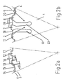
- FIGS 1 and 2a + b show a drive plate for multi-plate clutch systems known per se Kind, which in accordance with the invention to reduce rattling noises is trained.
- the essentially rotationally symmetrical drive plate 1 is present Case formed as a sheet metal part. It has external teeth 5 which are a plurality of at substantially the same distance x from one another teeth arranged on the outer periphery 21, of which exemplary eight in the drawing figures 1 and 2 by the reference numerals 7, 8, 9, 10, 11, 12, 13 and 14 are marked.
- the external or spline 5 of the driving plate 1 sits for the drive connection of the multi-plate clutch system in the internal toothing 6 of the clutch housing 4 of the multi-plate clutch system.
- the teeth 7, 8, 9, 10, 11, 12, 13, 14 engage with radial backlash ⁇ y 1 + ⁇ y 2 in the spaces between adjacent teeth 15, 16, 17, 18, 19, 20 of the internal teeth 6 of the clutch housing 4 Multi-plate clutch system. A section of such an intervention is shown in detail in FIG. 2a.
- At least one tooth in the circumferential direction is staggered.
- the embodiment according to the figures 1 and 2b has exactly one such tooth, which in the corresponding Figures is identified by the reference numeral 7.
- the transfer opposite the adjacent teeth 8 and 11 have an amount y.
- the distance this offset tooth 7 to the adjacent teeth 8 and 11 is due to whose x + y or x-y.
- the drive plate 1 is now inserted into the clutch housing 4 such that the offset tooth 7 is arranged offset in the direction of the thrust force acting on the drive plate 1.
- the offset y of the tooth 7 is chosen so that it exceeds the maximum backlash ⁇ y 1 + ⁇ y 2 .
- the offset tooth 7 is arranged to be elastically resilient in the circumferential direction.
- the resilient arrangement is realized by radially running incisions 22 and 23 separating the tooth 7 from the adjacent teeth 8 and 11.
- the preload is preferably chosen to be large enough to support the idling alternating torque.
- the offset y of the tooth 7 in the direction of the thrust force acting on the drive plate 1 causes all other teeth to bear against the tensile flank in preloaded operation. In driving mode (overrun), the offset teeth can make contact with the thrust flank due to the elastic design if the thrust torque is greater than the thrust torque portion in idle mode.
- an assembly aid is provided.
- This assembly aid exists in the present Embodiment according to Figures 1 and 2b from a radial direction arranged within the tooth 7 engagement opening 2 and another also in the radial direction to the adjacent tooth 8 arranged engagement opening 3.
- the two ends of one can in these engagement openings 2,3 Pliers or the like are inserted.
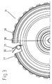
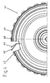
- FIGS. 3 and 4 show further variants of an embodiment according to the invention Driving plate 31, 41.
- the embodiment variant according to FIG. 3 is also based on a drive plate 31 in a known manner with an external toothing, which a A plurality of at substantially the same distance from each other on their outer circumference arranged teeth, three of which are exemplary the reference numerals 37, 38 and 39 are identified.
- a spiral spring 32, 33 is used instead of one of these teeth.
- the spring force of this spiral spring 32, 33 acts on the outer circumferential side in the circumferential direction.
- the outer peripheral side of this coil spring can now be in the space engage adjacent teeth on the internal teeth of the clutch housing and a bracing of the drive plate 31 with respect to the clutch housing cause in the circumferential direction.
- the coil spring 32, 33 in Figure 3 both in the relieved and in the tensioned State shown.
- a leaf spring can also be used.
- the corresponding parts of one such drive plate 41 are in the drawing figure 4 by the reference numerals 47, 48 and 49 (exemplary teeth) and 42 and 43 (leaf spring in the relaxed state or leaf spring in the tensioned state).
Landscapes
- Engineering & Computer Science (AREA)
- General Engineering & Computer Science (AREA)
- Mechanical Engineering (AREA)
- Mechanical Operated Clutches (AREA)
Abstract
Description
- Figur 1
- eine perspektivische Darstellung eines ersten Ausführungsbeispiels einer erfindungsgemäßen außenverzahnten Mitnehmerscheibe
- Figur 2
- eine Draufsicht auf die in einer Innenverzahnung eines Kupplungsgehäuses sitzenden erfindungsgemäßen außenverzahnten Mitnehmerscheibe gemäß Figur 1
- Figur 3
- ein zweites Ausführungsbeispiel einer erfindungsgemäßen außenverzahnten Mitnehmerscheibe in Draufsicht
- Figur 4
- ein drittes Ausführungsbeispiel einer erfindungsgemäßen außenver-zahnten Mitnehmescheibe in Draufsicht.
- 1
- Mitnehmerscheibe
- 2
- Eingriffsöffhung
- 3
- Eingriffsöffnung
- 4
- Kupplungsgehäuse
- 5
- Außenverzahnung
- 6
- Innenverzahnung
- 7
- Zahn
- 8
- Zahn
- 9
- Zahn
- 10
- Zahn
- 11
- Zahn
- 12
- Zahn
- 13
- Zahn
- 14
- Zahn
- 15
- Zahn
- 16
- Zahn
- 17
- Zahn
- 18
- Zahn
- 19
- Zahn
- 20
- Zahn
- 21
- Außenumfang
- 22
- Einschnitt
- 23
- Einschnitt
- 24
- Zahnflanke
- 31
- Mitnehmerscheibe
- 32
- Spiralfeder (unverspannter Zustand)
- 33
- Spiralfeder (verspannter Zustand)
- 37
- Zahn
- 38
- Zahn
- 39
- Zahn
- 41
- Mitnehmerscheibe
- 42
- Blattfeder (unverspannter Zustand)
- 43
- Blattfeder (verspannter Zustand)
- 47
- Zahn
- 48
- Zahn
- 49
- Zahn
- Δy1
- Distanz
- Δy2
- Distanz
- Δy1 + Δy2
- Flankenspiel
- x
- Distanz
- y
- Distanz
Claims (13)
- Mitnehmerscheibe (1) für Lamellenkupplungssysteme mit einer zum Einsetzen in eine Innenverzahnung (6) eines Kupplungsgehäuses (4) vorgesehenen Außenverzahnung (5), welche eine Mehrzahl von in im Wesentlichen gleichen Abstand (x) zueinander an dem Außenumfang (21) der Mitnehmerscheibe (1) angeordneten Zähne (7, 8, 9, 10, 11, 12, 13, 14) umfasst,
dadurch gekennzeichnet,dass wenigstens ein Zahn(7)in Umfangsrichtung versetzt (xxy) angeordnet ist. - Mitnehmerscheibe (1) nach Anspruch 1,
dadurch gekennzeichnet, dass der wenigstens eine Zahn (7) in Richtung einer an der Mitnehmerscheibe (1) angreifenden Schubkraft versetzt (y) angeordnet ist. - Mitnehmerscheibe (1) nach Anspruch 1 oder 2,
dadurch gekennzeichnet, dass der wenigstens eine Zahn (7) mindestens um ein maximales Verdrehflankenspiel (Δy1 + Δy2) versetzt (y) angeordnet ist. - Mitnehmerscheibe (1) nach einem der vorangegangenen Ansprüche,
dadurch gekennzeichnet, dass der wenigstens eine Zahn (7) in Umfangsrichtung elastisch fe- dernd angeordnet ist. - Mitnehmerscheibe (1) nach Anspruch 4,
dadurch gekennzeichnet, dass die elastisch federnde Anordnung mittels im Wesentlichen radial verlaufender den wenigstens einen Zahn (7) von dem benachbarten Zähnen (8, 11) trennender Einschnitte (22, 23) in der Mitnehmerscheibe (1) realisiert ist. - Mitnehmerscheibe (1) nach Anspruch 4 oder 5,
dadurch gekennzeichnet,dass die elastisch federnde Anordnung eine Vorspannung zwischen der Außenverzahnung (5) und der Innenverzahnung (6) hervorrufbar ausgebildet ist. - Mitnehmerscheibe (1) nach Anspruch 6,
dadurch gekennzeichnet, dass die Vorspannung ein Leerlaufwechselmoment abstützbar ausgelegt ist. - Mitnehmerscheibe (1) nach einem der Ansprüche 4 bis 7,
dadurch gekennzeichnet, dass die elastisch federnde Anordnung im Normalbetrieb ein Anliegen der jeweiligen Schubflanken der Zähne (15, 16, 17, 18, 19, 20) der Außenverzahnung (5) an den ensprechenden Schubflanken (24) der Zähne (7, 8, 9, 10, 11, 12, 13, 14) der Innenverzahnung (6) ermöglichbar ausgestaltet ist, falls das Schubmoment größer als das Schubmomentanteil im Leerlaufbetrieb ist. - Mitnehmerscheibe (1) nach einem der vorangegangenen Ansprüche,
dadurch gekennzeichnet, dass eine Montagehilfe (2,3) vorgesehen ist, welche ein Einsetzen der Außenverzahnung (5) der Mitnehmerscheibe (1) in die Innenverzahnung (6) des Kupplungsgehäuses (4) erleichtert. - Mitnehmerscheibe (1) nach Anspruch 9,
dadurch gekennzeichnet, dass die Montagehilfe eine im Wesentlichen in radialer Richtung innerhalb des wenigstens einen Zahns (7) angeordnete Eingriffs-öffnung (2) und eine im Wesentlichen in radialer Richtung innerhalb eines zu dem wenigstens einen Zahn (7) benachbarten Zahns (8) angeordnete Eingriffsöffnung (3) umfasst. - Mitnehmerscheibe (31, 41) für Lamellenkupplungssysteme mit einer zum Einsetzen in eine Innenverzahnung eines Kupplungsgehäuses vorgesehenen Außenverzahnung, welche eine Mehrzahl von in im Wesentlichen gleichem Abstand zueinander an dem Außenumfang an der Mitnehmerscheibe 31,41) angeordnete Zähne (37, 38, 39, 47, 48, 49) umfasst,
dadurch gekennzeichnet, dass anstelle von wenigstens einem der Zähne eine in Umfangsrichtung wirkende Federeinrichtung (32, 42; 33, 43) eingesetzt ist. - Mitnehmerscheibe (31, 41) nach Anspruch 11,
dadurch gekennzeichnet, dass die Fe-dereinrichtung eine Spiralfeder (32, 33), eine Blattfeder (42, 43) oder dergleichen ist. - Mitnehmerscheibe (31, 41) nach Anspruch 11 oder 12,
dadurch gekennzeichnet, dass die Fe- dereinrichtung außenumfangsseitig einen Zahn trägt.
Priority Applications (5)
| Application Number | Priority Date | Filing Date | Title |
|---|---|---|---|
| DE50213480T DE50213480D1 (de) | 2002-06-15 | 2002-06-15 | Mitnehmerscheibe für Lamellenkupplungssysteme |
| EP02013205A EP1371867B1 (de) | 2002-06-15 | 2002-06-15 | Mitnehmerscheibe für Lamellenkupplungssysteme |
| JP2003161899A JP2004069052A (ja) | 2002-06-15 | 2003-06-06 | マルチディスク・クラッチ装置用駆動ディスク |
| KR10-2003-0037911A KR20030096059A (ko) | 2002-06-15 | 2003-06-12 | 플레이트 클러치 시스템용 도그 플레이트 |
| US10/462,140 US6915892B2 (en) | 2002-06-15 | 2003-06-16 | Driving plate for multi-plate clutch system |
Applications Claiming Priority (1)
| Application Number | Priority Date | Filing Date | Title |
|---|---|---|---|
| EP02013205A EP1371867B1 (de) | 2002-06-15 | 2002-06-15 | Mitnehmerscheibe für Lamellenkupplungssysteme |
Publications (2)
| Publication Number | Publication Date |
|---|---|
| EP1371867A1 true EP1371867A1 (de) | 2003-12-17 |
| EP1371867B1 EP1371867B1 (de) | 2009-04-22 |
Family
ID=29558339
Family Applications (1)
| Application Number | Title | Priority Date | Filing Date |
|---|---|---|---|
| EP02013205A Expired - Lifetime EP1371867B1 (de) | 2002-06-15 | 2002-06-15 | Mitnehmerscheibe für Lamellenkupplungssysteme |
Country Status (5)
| Country | Link |
|---|---|
| US (1) | US6915892B2 (de) |
| EP (1) | EP1371867B1 (de) |
| JP (1) | JP2004069052A (de) |
| KR (1) | KR20030096059A (de) |
| DE (1) | DE50213480D1 (de) |
Cited By (8)
| Publication number | Priority date | Publication date | Assignee | Title |
|---|---|---|---|---|
| EP1589244A1 (de) * | 2004-04-21 | 2005-10-26 | BorgWarner Inc. | Mitnehmereinheit mit axial vorgespannter Mitnehmerscheibe |
| EP2014943A1 (de) * | 2007-07-10 | 2009-01-14 | Volkswagen Aktiengesellschaft | Kupplung, vzw. Doppelkupplung für ein Kraftfahrzeug |
| EP1657472A3 (de) * | 2004-11-13 | 2009-02-18 | LuK Lamellen und Kupplungsbau Beteiligungs KG | Axiale Steckverbindungsanordnung |
| FR2922619A1 (fr) * | 2007-10-17 | 2009-04-24 | Valeo Embrayages | Dispositif d'accouplement hydrocinetique comportant un embrayage de verrouillage multi-disques equipe de moyens elastiques de precontrainte circonferentielle |
| EP2246584A1 (de) * | 2009-04-27 | 2010-11-03 | Hoerbiger Antriebstechnik GmbH | Kupplung |
| WO2011076175A1 (de) * | 2009-12-21 | 2011-06-30 | Schaeffler Technologies Gmbh & Co. Kg | Vorrichtung mit einer steckverbindung |
| WO2017202409A1 (de) * | 2016-05-27 | 2017-11-30 | Schaeffler Technologies AG & Co. KG | Reibungskupplung |
| DE102016202179B4 (de) * | 2015-02-12 | 2024-03-14 | Schaeffler Technologies AG & Co. KG | Kupplungseinrichtung |
Families Citing this family (5)
| Publication number | Priority date | Publication date | Assignee | Title |
|---|---|---|---|---|
| FR2881196B1 (fr) * | 2005-01-27 | 2007-03-16 | Renault Sas | Systeme d'embrayage humide multiple comprenant un flasque d'entrainement a languettes de centrage |
| US8272115B2 (en) * | 2005-04-27 | 2012-09-25 | Leif Lewis | Multi-plate clutch and method |
| EP1899617B1 (de) * | 2005-06-28 | 2019-02-13 | Schaeffler Technologies AG & Co. KG | Kupplungssystem |
| WO2008046379A1 (de) * | 2006-10-21 | 2008-04-24 | Luk Lamellen Und Kupplungsbau Beteiligungs Kg | Kupplungsaggregat |
| EP1983207B1 (de) * | 2007-04-16 | 2012-06-20 | Schaeffler Technologies AG & Co. KG | Mitnehmereinheit für eine Kupplungsanordnung, insbesondere eine nasslaufende Doppelkupplungsanordnung |
Citations (3)
| Publication number | Priority date | Publication date | Assignee | Title |
|---|---|---|---|---|
| US3803872A (en) * | 1972-03-28 | 1974-04-16 | Renk Ag Zahnraeder | Toothed coupling for rotatable members |
| US6210280B1 (en) * | 1995-07-24 | 2001-04-03 | Exedy Corporation | Damper disc assembly having non-rotatable spring seats |
| US6397997B2 (en) * | 1999-12-06 | 2002-06-04 | Honda Giken Kogyo Kabushiki Kaisha | Friction engaging device |
Family Cites Families (16)
| Publication number | Priority date | Publication date | Assignee | Title |
|---|---|---|---|---|
| US3245508A (en) * | 1966-04-12 | Damper | ||
| US1518604A (en) * | 1920-03-31 | 1924-12-09 | Locomobile Co America | Friction clutch |
| US1467732A (en) * | 1921-07-13 | 1923-09-11 | Harold H Emmons | Clutch disk |
| US2968381A (en) * | 1957-09-27 | 1961-01-17 | Gen Motors Corp | Friction plate |
| US4679679A (en) * | 1985-07-11 | 1987-07-14 | Borg-Warner Automotive, Inc. | Clutch driven plate assembly with anti-backlash damping |
| DE3726641C1 (de) * | 1987-08-11 | 1988-12-29 | Viscodrive Gmbh | Fluessigkeitsreibungskupplung |
| DE3927584C1 (de) * | 1989-08-22 | 1990-04-26 | Viscodrive Gmbh, 5204 Lohmar, De | |
| JP3336540B2 (ja) * | 1992-03-24 | 2002-10-21 | 本田技研工業株式会社 | 動力伝達装置の防振機構 |
| GB9303487D0 (en) * | 1993-02-22 | 1993-04-07 | Yang Tai Her | Structure and device for extinguishing flexible gear lash |
| JP3436590B2 (ja) * | 1994-07-28 | 2003-08-11 | ジヤトコ株式会社 | 締結装置 |
| JP3537597B2 (ja) * | 1996-07-05 | 2004-06-14 | ジヤトコ株式会社 | 動力伝達部のスプライン結合構造 |
| KR19980034276U (ko) * | 1996-12-10 | 1998-09-15 | 박병재 | 디젤엔진용 클러치 디스크 앗세이의 프리 댐퍼구조 |
| JP3991391B2 (ja) * | 1997-05-30 | 2007-10-17 | アイシン・エィ・ダブリュ株式会社 | 多板クラッチ及びそのクラッチドラムの成形方法並びに成形装置 |
| US5979627A (en) * | 1997-12-10 | 1999-11-09 | Means Industries, Inc. | Damper assembly |
| JP2001227561A (ja) * | 2000-02-15 | 2001-08-24 | Valeo Unisia Transmission Kk | クラッチ装置 |
| DE10202386A1 (de) * | 2001-02-19 | 2002-08-22 | Heidelberger Druckmasch Ag | Lamellenkupplung |
-
2002
- 2002-06-15 DE DE50213480T patent/DE50213480D1/de not_active Expired - Lifetime
- 2002-06-15 EP EP02013205A patent/EP1371867B1/de not_active Expired - Lifetime
-
2003
- 2003-06-06 JP JP2003161899A patent/JP2004069052A/ja active Pending
- 2003-06-12 KR KR10-2003-0037911A patent/KR20030096059A/ko not_active Ceased
- 2003-06-16 US US10/462,140 patent/US6915892B2/en not_active Expired - Fee Related
Patent Citations (3)
| Publication number | Priority date | Publication date | Assignee | Title |
|---|---|---|---|---|
| US3803872A (en) * | 1972-03-28 | 1974-04-16 | Renk Ag Zahnraeder | Toothed coupling for rotatable members |
| US6210280B1 (en) * | 1995-07-24 | 2001-04-03 | Exedy Corporation | Damper disc assembly having non-rotatable spring seats |
| US6397997B2 (en) * | 1999-12-06 | 2002-06-04 | Honda Giken Kogyo Kabushiki Kaisha | Friction engaging device |
Cited By (12)
| Publication number | Priority date | Publication date | Assignee | Title |
|---|---|---|---|---|
| EP1589244A1 (de) * | 2004-04-21 | 2005-10-26 | BorgWarner Inc. | Mitnehmereinheit mit axial vorgespannter Mitnehmerscheibe |
| EP1657472A3 (de) * | 2004-11-13 | 2009-02-18 | LuK Lamellen und Kupplungsbau Beteiligungs KG | Axiale Steckverbindungsanordnung |
| EP2014943A1 (de) * | 2007-07-10 | 2009-01-14 | Volkswagen Aktiengesellschaft | Kupplung, vzw. Doppelkupplung für ein Kraftfahrzeug |
| FR2922619A1 (fr) * | 2007-10-17 | 2009-04-24 | Valeo Embrayages | Dispositif d'accouplement hydrocinetique comportant un embrayage de verrouillage multi-disques equipe de moyens elastiques de precontrainte circonferentielle |
| WO2009053656A3 (fr) * | 2007-10-17 | 2009-07-02 | Valeo Embrayages | Dispositif d'accouplement hydrocinetique comportant un embrayage de verrouillage equipe de moyens elastiques de precontrainte circonferentielle |
| US8479902B2 (en) | 2007-10-17 | 2013-07-09 | Valeo Embrayages | Hydrokinetic coupling device comprising lock-up clutch equipped with elastic means of circumferential preload |
| US8857588B2 (en) | 2007-10-17 | 2014-10-14 | Valeo Embrayages | Hydrokinetic coupling device comprising lock-up clutch equipped with elastic means of circumferential preload |
| DE112008002772B4 (de) * | 2007-10-17 | 2019-08-14 | Valeo Embrayages | Hydrodynamische Kupplungsvorrichtung mit einer mit elastischen Vorspannmitteln ausgestatteten Überbrückungskupplung |
| EP2246584A1 (de) * | 2009-04-27 | 2010-11-03 | Hoerbiger Antriebstechnik GmbH | Kupplung |
| WO2011076175A1 (de) * | 2009-12-21 | 2011-06-30 | Schaeffler Technologies Gmbh & Co. Kg | Vorrichtung mit einer steckverbindung |
| DE102016202179B4 (de) * | 2015-02-12 | 2024-03-14 | Schaeffler Technologies AG & Co. KG | Kupplungseinrichtung |
| WO2017202409A1 (de) * | 2016-05-27 | 2017-11-30 | Schaeffler Technologies AG & Co. KG | Reibungskupplung |
Also Published As
| Publication number | Publication date |
|---|---|
| JP2004069052A (ja) | 2004-03-04 |
| DE50213480D1 (de) | 2009-06-04 |
| US6915892B2 (en) | 2005-07-12 |
| US20040055842A1 (en) | 2004-03-25 |
| EP1371867B1 (de) | 2009-04-22 |
| KR20030096059A (ko) | 2003-12-24 |
Similar Documents
| Publication | Publication Date | Title |
|---|---|---|
| EP1382872B1 (de) | Mitnehmereinheit für Lamellenkupplungssysteme | |
| EP1983207B1 (de) | Mitnehmereinheit für eine Kupplungsanordnung, insbesondere eine nasslaufende Doppelkupplungsanordnung | |
| EP2097657B1 (de) | Torsionsschwingungsdämpfer mit mehrteiligem primärelement | |
| EP1371867B1 (de) | Mitnehmerscheibe für Lamellenkupplungssysteme | |
| DE102008063662A1 (de) | Lamelle für eine reibschlüssig arbeitende Einrichtung und reibschlüssig arbeitende Einrichtung mit einer solchen Lamelle | |
| DE69703930T2 (de) | Ein gerät zur isolation von drehmomentschwingungen | |
| DE112013003280B4 (de) | Nachgiebige Getriebeanordnung mit variabler Federkraft | |
| EP2012044A1 (de) | Mechanischer Torsionsschwingungsdämpfer | |
| DE102006010270B4 (de) | Zahnradanordnung | |
| DE112007000558T5 (de) | Drehmomentbegrenzer | |
| DE10118233A1 (de) | Getriebe mit rasselfreier Verbindung zwischen Kupplungskorb und Mitnehmerscheibe | |
| EP1353086B1 (de) | Torsionsschwingungsdämpfer sowie Versteifungselement für einen solchen | |
| DE19727680B4 (de) | Schwungmassenvorrichtung mit einer Verliersicherung | |
| DE102011079603A1 (de) | Kupplungsscheibe für eine Reibungskupplung | |
| EP0666430A1 (de) | Wellenkupplung | |
| DE102014212844A1 (de) | Welle-Nabe-Verbindung zur Drehmomentübertragung in einem Antriebsstrang eines Kraftfahrzeugs, Verfahren zur Montage einer derartigen Welle-Nabe-Verbindung sowie Verfahren zum Betrieb eines Antriebsstrangs mit einer deartigen Welle-Nabe-Verbindung | |
| EP1589244B1 (de) | Mitnehmereinheit mit axial vorgespannter Mitnehmerscheibe | |
| EP2100053A1 (de) | Torsionsschwingungsdämpfer mit endschuhen und antriebsstrang mit einem solchen torsionsschwingungsdämpfer | |
| DE602006000393T2 (de) | Reibungskupplung, insbesondere für Kraftfahrzeug, mit verbesserten Federscheiben | |
| DE102010055192A1 (de) | Verbrennungsmotor mit Führung zum Abstecken der Nockenwelle sowie Verschlusselement | |
| DE102007015104A1 (de) | Kopplungseinrichtung und Kupplungsanordnung mit einer solchen Kopplungseinrichtung | |
| DE102010062325A1 (de) | Riemenantrieb mit Torsionsdämpfer | |
| DE102006055220B4 (de) | Kraftübertragungsaggregat mit zwei drehbaren Bauteilen | |
| DE102021213313A1 (de) | Welle-Nabe-Verbindung | |
| DE102016208120A1 (de) | Reibscheibe für einen Kupplungsscheibendämpfer |
Legal Events
| Date | Code | Title | Description |
|---|---|---|---|
| PUAI | Public reference made under article 153(3) epc to a published international application that has entered the european phase |
Free format text: ORIGINAL CODE: 0009012 |
|
| AK | Designated contracting states |
Kind code of ref document: A1 Designated state(s): AT BE CH CY DE DK ES FI FR GB GR IE IT LI LU MC NL PT SE TR |
|
| AX | Request for extension of the european patent |
Extension state: AL LT LV MK RO SI |
|
| 17P | Request for examination filed |
Effective date: 20040206 |
|
| AKX | Designation fees paid |
Designated state(s): DE FR GB IT |
|
| RAP1 | Party data changed (applicant data changed or rights of an application transferred) |
Owner name: BORGWARNER INC. |
|
| 17Q | First examination report despatched |
Effective date: 20070223 |
|
| GRAP | Despatch of communication of intention to grant a patent |
Free format text: ORIGINAL CODE: EPIDOSNIGR1 |
|
| GRAS | Grant fee paid |
Free format text: ORIGINAL CODE: EPIDOSNIGR3 |
|
| GRAA | (expected) grant |
Free format text: ORIGINAL CODE: 0009210 |
|
| AK | Designated contracting states |
Kind code of ref document: B1 Designated state(s): DE FR GB IT |
|
| REG | Reference to a national code |
Ref country code: GB Ref legal event code: FG4D Free format text: NOT ENGLISH |
|
| REF | Corresponds to: |
Ref document number: 50213480 Country of ref document: DE Date of ref document: 20090604 Kind code of ref document: P |
|
| PLBE | No opposition filed within time limit |
Free format text: ORIGINAL CODE: 0009261 |
|
| STAA | Information on the status of an ep patent application or granted ep patent |
Free format text: STATUS: NO OPPOSITION FILED WITHIN TIME LIMIT |
|
| GBPC | Gb: european patent ceased through non-payment of renewal fee |
Effective date: 20090722 |
|
| REG | Reference to a national code |
Ref country code: FR Ref legal event code: ST Effective date: 20100226 |
|
| 26N | No opposition filed |
Effective date: 20100125 |
|
| PG25 | Lapsed in a contracting state [announced via postgrant information from national office to epo] |
Ref country code: FR Free format text: LAPSE BECAUSE OF NON-PAYMENT OF DUE FEES Effective date: 20090630 |
|
| PG25 | Lapsed in a contracting state [announced via postgrant information from national office to epo] |
Ref country code: GB Free format text: LAPSE BECAUSE OF NON-PAYMENT OF DUE FEES Effective date: 20090722 |
|
| PG25 | Lapsed in a contracting state [announced via postgrant information from national office to epo] |
Ref country code: IT Free format text: LAPSE BECAUSE OF FAILURE TO SUBMIT A TRANSLATION OF THE DESCRIPTION OR TO PAY THE FEE WITHIN THE PRESCRIBED TIME-LIMIT Effective date: 20090422 |
|
| PGFP | Annual fee paid to national office [announced via postgrant information from national office to epo] |
Ref country code: DE Payment date: 20190515 Year of fee payment: 18 |
|
| REG | Reference to a national code |
Ref country code: DE Ref legal event code: R119 Ref document number: 50213480 Country of ref document: DE |
|
| PG25 | Lapsed in a contracting state [announced via postgrant information from national office to epo] |
Ref country code: DE Free format text: LAPSE BECAUSE OF NON-PAYMENT OF DUE FEES Effective date: 20210101 |