EP1371777A2 - Befeuchtungseinrichtung - Google Patents
Befeuchtungseinrichtung Download PDFInfo
- Publication number
- EP1371777A2 EP1371777A2 EP03010144A EP03010144A EP1371777A2 EP 1371777 A2 EP1371777 A2 EP 1371777A2 EP 03010144 A EP03010144 A EP 03010144A EP 03010144 A EP03010144 A EP 03010144A EP 1371777 A2 EP1371777 A2 EP 1371777A2
- Authority
- EP
- European Patent Office
- Prior art keywords
- water
- roller
- humidification device
- discharge pipe
- roll
- Prior art date
- Legal status (The legal status is an assumption and is not a legal conclusion. Google has not performed a legal analysis and makes no representation as to the accuracy of the status listed.)
- Withdrawn
Links
- XLYOFNOQVPJJNP-UHFFFAOYSA-N water Substances O XLYOFNOQVPJJNP-UHFFFAOYSA-N 0.000 claims abstract description 92
- 239000007921 spray Substances 0.000 claims abstract description 19
- 239000002184 metal Substances 0.000 claims abstract description 5
- 239000000463 material Substances 0.000 claims description 35
- 239000011248 coating agent Substances 0.000 claims description 22
- 238000000576 coating method Methods 0.000 claims description 22
- 239000011111 cardboard Substances 0.000 claims description 3
- 239000011087 paperboard Substances 0.000 claims description 3
- 238000000034 method Methods 0.000 abstract description 2
- 238000009736 wetting Methods 0.000 abstract 1
- 239000000123 paper Substances 0.000 description 32
- 238000005507 spraying Methods 0.000 description 4
- 238000009825 accumulation Methods 0.000 description 2
- 238000003490 calendering Methods 0.000 description 2
- 238000009434 installation Methods 0.000 description 2
- 238000009833 condensation Methods 0.000 description 1
- 230000005494 condensation Effects 0.000 description 1
- 238000010276 construction Methods 0.000 description 1
- 230000000694 effects Effects 0.000 description 1
- 239000008141 laxative Substances 0.000 description 1
- 230000002475 laxative effect Effects 0.000 description 1
- 238000012423 maintenance Methods 0.000 description 1
- 230000000149 penetrating effect Effects 0.000 description 1
- 239000002352 surface water Substances 0.000 description 1
Images


Classifications
-
- D—TEXTILES; PAPER
- D21—PAPER-MAKING; PRODUCTION OF CELLULOSE
- D21G—CALENDERS; ACCESSORIES FOR PAPER-MAKING MACHINES
- D21G1/00—Calenders; Smoothing apparatus
- D21G1/0073—Accessories for calenders
- D21G1/0093—Web conditioning devices
-
- D—TEXTILES; PAPER
- D21—PAPER-MAKING; PRODUCTION OF CELLULOSE
- D21G—CALENDERS; ACCESSORIES FOR PAPER-MAKING MACHINES
- D21G7/00—Damping devices
Definitions
- the present invention relates to a device for moistening a moving material web, in particular paper or cardboard web.
- the most important satin conditions include pressure and temperature also the moistening of the paper web. This is especially true for the concept of a so-called "Janus” calender.
- the required moisture of the paper is in two stages generated.
- the paper web is moistened directly after the dryer section of the paper machine with a nozzle humidifier, if the calender is arranged offline.
- the setting of the residual moisture the paper web in the dryer section of the paper machine takes place in the case an online calender.
- humidification takes place in the Calender using a steam dehumidifier, both offline and online can happen.
- a humidification device is known from DE-AS 1 295 993, which is formed by a stationary deflecting beam over which the paper web Steam can be applied and steam outlet openings accordingly is provided.
- the aim of the invention is to provide an improved moistening device to create the type mentioned, in which the aforementioned disadvantages are eliminated.
- the roller is preferably designed at the same time as a guide roller.
- porous outer coating is preferably a highly porous coating provided over which at least essentially the entire touched Material surface is moistened evenly.
- the porous outer coating can in particular consist of hydrophilic material.
- the humidifier can in particular can also be used where there is only a relatively small installation space is available. It is therefore also problem-free, for example Can be used within a multi-roll calender.
- the Dampening roller according to the invention at the same time the function of a conventional one Take over guide roller.
- a conventional paper guide roller can be installed instead of one conventional paper guide roller can be installed.
- Dampening roller is among others also ensured that primarily only the Web surface or the web only moistened to a limited depth becomes. This can, for example, increase the risk of being completely damp Paper web can be encountered in the satin.
- the invention Dampening roller is not only for example in a multi-roller calender, but can basically be used at any point on a web guide, the dampening roller according to the invention in each case in particular can be used instead of a conventional guide roller.
- the dampening roller according to the invention can therefore primarily be used instead a conventional web or paper guide roller are installed, wherein attention should be paid to a sufficiently large wrap angle should.
- the pressure with which the inside of the roll shell is exposed to water is preferably chosen so that the water due to this Pressure is at least partially pressed into the roll shell.
- the roller jacket only over part of its inner circumference, i.e. about one correspondingly limited angular range, exposed to water.
- the roller shell can in particular be a perforated tubular Include support body to which the porous outer coating is applied is.
- the perforated tubular support body can for example be made of Metal.
- the porous outer coating can especially a highly porous, especially hydrophilic coating act.
- Such a, in particular two-part construction of the roll shell is especially useful to support satin.
- an appropriate e.g. metal pipe becomes the required Stability of the roll shell guaranteed.
- On the outside of the tube can then the particularly highly porous coating of hydrophilic Material are applied.
- porous or highly porous coating is therefore excluded, that when moistening the perforation pattern of the support tube on the Material web is transferred, which become visible in the satined product would. Due to the porous or highly porous coating according to the invention So it is guaranteed that the promoted to the outside Water distributed as evenly as possible and at least the majority of the Material surface is wetted with water.
- the application device preferably comprises several across the roll width distributed, separately controllable order zones. It can different order zones each have at least one separately controllable Be assigned water valve through which water can be fed to a nozzle is.
- a spray device is provided.
- This spray device preferably comprises several, distributed over the roll width, separated controllable spray zones.
- the different application or spray zones can at least a separately controllable water valve can be assigned, via which one Nozzle or spray nozzle water can be supplied.
- valves distributed over the width of the roller this can in particular Moisture cross profile and thus the gloss and / or smoothness profile of each Paper web can be influenced in the desired manner.
- the water supply is preferably carried out via an inside the roller arranged fixed water pressure pipe.
- Such a fixed water pressure pipe can, for example Water valves distributed over the roller width are supplied. about the preferably individually controllable valves can then the water applied to the inner surface of the roll shell via a nozzle or sprayed. Because of the distribution of water in the coat unlike e.g. with a nozzle moistener, none at this point placed greater demands on the drop quality after the nozzles become.
- a fixed discharge pipe is advantageously located inside the roller arranged over which excess water can be removed. You can in particular, means can also be provided to remove the excess Attributed water to the water cycle.
- a creator is expediently assigned to the discharge pipe, via which the downward water is fed to the discharge pipe.
- the creator is preferably on the inside of the roll shell.
- the drain pipe can expediently have a slope.
- the outside diameter is of the discharge pipe is smaller than the inside diameter of the Roll shell.
- a respective nozzle can advantageously in the Area arranged between the discharge pipe and the roll shell and via a radial line passing through the jacket of the discharge pipe be connected to the water pressure pipe.
- Excess water can thus be removed, for example, that it is due to one lying against the inside of the roll shell Creator is guided into a second fixed tube, which in particular can serve the return of water.
- the laxative or return pipe installed in particular with a certain slope become.
- the internal water supply or spraying are set so that most of the water directly when it hits the inside of the jacket picked up by the roller jacket and onto the material web, e.g. Paper web, is transferred. A so-called "throwing out" of water in the area of the roller surface not touched by the material web is therefore excluded.
- such an embodiment is particularly advantageous in which the outer diameter of the discharge pipe at least approximately the same size as that
- the inside diameter of the roll shell and the discharge pipe is one over part of its scope, i.e. over a limited angular range, has extending recess, through which the inside water can be applied to the roll shell.
- the roller can only be driven via the material web or with be provided with a separate drive.
- the roller shell can be at least essentially radial its inner surface impinging water jet or with an oblique its inner surface hitting or approximately tangential to it Water jet can be acted upon.
- the coefficient of friction ranges between the roller surface and the paper web not for an exclusive Drive over the material web, so can the inner surface so that the water is roughly tangential strikes the inner surface of the roller. In this way, the impact or Impulse of the impinging water used to drive the roller become.
- the moistening device formed by a dampening roller can advantageously instead of a conventional guide roller within the Material web guidance can be used.
- the dampening roller can be used instead of a conventional one Guide roller can be used in a multi-roll calender. It is in particular use following between a thermo roll and a counter roll formed nip conceivable. In certain cases it is also advantageous if such a one is provided behind a "hot" nip Dampening roller in combination with one before entering it Nip provided steam humidifier is used.
- Figure 1 shows a schematic representation of a first embodiment a device 10 of a moving material web 12, which is can in particular be a paper or cardboard web.
- the running direction the material web 12 is indicated in FIG. 1 by arrows L.
- the moistening device 10 comprises a rotatable material web 12 roller 14 leading along a defined wrapping area, simultaneously in the manner described in more detail below serves as a guide roller and dampening roller.
- the roller 14 has a water-permeable, a porous outer coating 16 having jacket 18, in particular a perforated may include tubular support body 20 on which a highly porous outer coating 16 applied in particular from hydrophilic material is.
- the inside of the roll shell 18 is by means of an application device 22 can be acted upon with water, for example here by a spray device is formed.
- the pressure with which the inside of the roll shell 18 with water is sprayed is expediently chosen so that the water as a result of this pressure is at least partially pressed into the roller jacket 18. Due to the rotation of the roller 14, the water is supported by the centrifugal force through the jacket 18 on its outer surface promoted. On this outer surface of the jacket 18 is at the same time the material web 12 out, which is thus in with the escaping water Contact comes.
- the roller 14 can be used instead of a conventional paper guide roller be installed, with a sufficiently large wrap angle to watch out for. In the present case, this is the wrap angle for example approximately 180 °.
- the perforated tubular support body 20 can be made of metal, for example consist.
- roller jacket 18 is only over part of its inner circumference, i.e. only limited Changing area, supplied with water.
- the spraying device 22 can have several, distributed over the roll width, comprise separately controllable spray zones.
- the different Spray zones each have at least one separately controllable water valve be assigned, via which a respective spray nozzle 24 water is feedable. With the help of the valves distributed over the roller width the moisture cross profile and thus the gloss and / or smoothness profile of the Material web 12 are influenced.
- the water supply takes place via a arranged in the interior of the roller 14 fixed water pressure pipe 26.
- a fixed discharge pipe 28 may be arranged over the excess water can be removed.
- it can also Coils can be provided around the discharged via this discharge pipe 28 excess water can be attributed to the water cycle.
- the discharge pipe 28 is adjacent to the inside of the roll shell 18 Creator 30 assigned through which the excess water to the Drain pipe 28 is fed.
- the discharge pipe 28 can have a certain slope.
- the fixed water pressure pipe 26 arranged within the fixed discharge pipe 28 his.
- the outside diameter of the discharge pipe 28 significantly smaller than the inside diameter of the roll shell 14.
- the illustrated embodiment is the relevant diameter of the Drain pipe 28 about half the size of the diameter in question Roll jacket 14.
- a respective spray or water nozzle 24 is in the area between the discharge pipe 28 and the roller jacket 18 arranged and via a radial line 32 passing through the jacket of the discharge pipe 28 connected to the water pressure pipe 26.
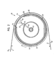
- the outer diameter of the The discharge pipe 28 is approximately the same size as the inside diameter of the Roller jacket 18.
- the discharge pipe 28 has one over part of its scope, i.e. over a limited angular range, extending recess 34 through which the inside of the Roll shell 18 by means of the spray device 22 with water is acted upon.
- the fixed discharge pipe 28 leaves only one relatively narrow angular range for the inner spraying of the roll shell 18 free.
- this embodiment can at least in accordance with FIG Again have essentially the same structure as that of Figure 1. Corresponding parts are assigned the same reference numerals.
- the roller 14 can only be driven via the material web 12 or be provided with a separate drive.
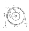
- the spray or water nozzles 24 are arranged in the interior of the roller 14 in such a way that the roller jacket 18 can be acted upon by a water jet 36 ′ which strikes its inner surface obliquely or is approximately tangential to it. In this way, the impact or impulse of the water striking the inner surface of the roll shell 18 can be used to drive the roll 14.
- this embodiment can at least essentially have the same structure as the embodiment according to FIG. 1 or the embodiment according to FIG. 2.
- Corresponding parts are assigned the same reference numerals. While the discharge pipe 28 and the scoop 30 are designed in FIG. 3 as in the embodiment according to FIG. 1, such a design of the discharge pipe 28 and scoop 30 as is shown in FIG. 2 is also conceivable.
- dampening roller 14 can be used instead of one conventional guide roller within the material or paper web guide be provided.
- FIG. 4 schematically shows a multi-roll calender 38, in which the humidifier instead of a conventional guide roller 10 forming dampening roller 14 is used.
- the multi-roll calender comprises 38 two elastic rollers 40, 42 and one arranged between them Thermo roll 44, so that two so-called “hot” nips 46, 48 result.
- the one that forms the moistening device 10 Dampening roller 14 following that between the elastic roller 40 and the first "hot” nip 46 formed by the thermal roller 44.
- this can be after the first "Hot" nip 46 provided moistening device 10 or dampening roller 14 in particular in combination with a before entering the first "hot” nip 46 provided steam humidifier 50 can be used.
- the steam humidifier 50 is in contact with the thermal roller 44 coming side of the paper web 12 arranged.
- the material web 12 is viewed in the web running direction L before the first "hot” nip 46 and after the second "hot” nip 48, respectively guided over a conventional guide roller or paper guide roller 52.
- the dampening roller 14 can in particular be designed again as this e.g. has been described with reference to Figures 1 to 3.
Landscapes
- Paper (AREA)
- Registering, Tensioning, Guiding Webs, And Rollers Therefor (AREA)
- Rotary Presses (AREA)
Abstract
Description
Sowohl die Befeuchtung der Bahn mittels eines Düsenfeuchters als auch die Aufrechterhaltung einer Restfeuchte nach der Papiermaschine bringt jeweils den Nachteil mit sich, dass die Feuchte über die gesamte Papierdicke gleich ist. Zwar wird mittels eines Düsenfeuchters das Wasser nur auf die Oberfläche aufgebracht, während der Lagerung des auf einen Tambour aufgerollten fertigen Wickels durchdringt das Wasser jedoch alle Schichten des Papiers. Eine solche Durchfeuchtung der Bahn fördert wieder die Schwarzsatinage.
- Figur 1
- eine schematische Darstellung einer ersten Ausführungsform einer durch eine Feuchtewalze gebildeten Befeuchtungseinrichtung, bei der der Wasserstrahl zumindest im Wesentlichen radial auf die Innenfläche des Walzenmantels auftrifft,
- Figur 2
- eine schematische Darstellung einer weiteren Ausführungsform der durch eine Feuchtewalze gebildeten Befeuchtungseinrichtung mit einer zumindest im wesentlichen radialen Beaufschlagung der Innenfläche des Walzenmantels, wobei in diesem Fall jedoch ein Abführrohr vorgesehen ist, dessen Außendurchmesser zumindest annähernd gleich groß ist wie der Innendurchmesser des Walzenmantels,
- Figur 3
- eine schematische Darstellung einer weiteren Ausführungsform der durch eine Feuchtewalze gebildeten Befeuchtungseinrichtung, bei der die Innenfläche des Walzenmantels mit einem schräg auftreffenden Wasserstrahl beaufschlagt wird, und
- Figur 4
- eine schematische Darstellung eines Mehrwalzenkalanders, in dem anstelle einer herkömmlichen Leitwalze eine Feuchtewalze eingesetzt ist.
Im übrigen kann diese Ausführungsform zumindest im wesentlichen wieder den gleichen Aufbau wie die Ausführung gemäß Figur 1 oder die Ausführung gemäß Figur 2 besitzen. Einander entsprechenden Teilen sind gleiche Bezugszeichen zugeordnet. Während in der Figur 3 das Abführrohr 28 sowie der Schöpfer 30 so wie bei der Ausführungsform gemäß Figur 1 ausgeführt sind, ist grundsätzlich beispielsweise auch wieder eine solche Ausführung des Abführrohres 28 sowie des Schöpfers 30 denkbar, wie sie in der Figur 2 wiedergegeben ist.
- 10
- Befeuchtungseinrichtung
- 12
- Materialbahn
- 14
- Walze, Feuchtewalze
- 16
- hochporöse äußere Beschichtung
- 18
- Walzenmantel
- 20
- perforierter rohrförmiger Tragkörper
- 22
- Auftragseinrichtung, Sprüheinrichtung
- 24
- Sprühdüse
- 26
- feststehendes Wasserdruckrohr
- 28
- feststehendes Abführrohr
- 30
- Schöpfer
- 32
- Leitung
- 34
- Aussparung
- 36
- Wasserstrahl
- 36'
- Wasserstrahl
- 38
- Mehrwalzenkalander
- 40
- elastische Walze
- 42
- elastische Walze
- 44
- Thermowalze
- 46
- "heißer" Nip
- 48
- "heißer" Nip
- 50
- Dampffeuchter
- 52
- Leitwalze, Papierleitwalze
- L
- Bahnlaufrichtung
Claims (30)
- Einrichtung zur Befeuchtung (10) einer bewegten Materialbahn (12), insbesondere Papier- oder Kartonbahn,
gekennzeichnet durch
eine drehbare, die Materialbahn (12) entlang eines definierten Umschlingungsbereiches führende Walze (14) mit einem wasserdurchlässigen, eine poröse äußere Beschichtung (16) aufweisenden Mantel (18), dessen Innenseite mittels einer Auftragseinrichtung (22) mit Wasser beaufschlagbar ist und über dessen poröse äußere Beschichtung (16) die Materialbahn (12) mit aus dem Walzenmantel (18) austretendem Wasser befeuchtet wird. - Befeuchtungseinrichtung nach Anspruch 1,
dadurch gekennzeichnet, dass die Walze (14) gleichzeitig als Leitwalze ausgeführt ist. - Befeuchtungseinrichtung nach Anspruch 1 oder 2,
dadurch gekennzeichnet, dass eine hochporöse Beschichtung (16) vorgesehen ist, über die zumindest im Wesentlichen die gesamte berührte Materialbahnoberfläche gleichmäßig befeuchtet wird. - Befeuchtungseinrichtung nach einem der vorhergehenden Ansprüche,
dadurch gekennzeichnet, dass die poröse äußere Beschichtung (16) aus hydrophilem Material besteht. - Befeuchtungseinrichtung nach einem der vorhergehenden Ansprüche,
dadurch gekennzeichnet, dass der Druck, mit dem die Innenseite des Walzenmantels (18) mit Wasser beaufschlagt wird, so gewählt ist, dass das Wasser infolge dieses Drucks zumindest teilweise in den Walzenmantel (18) gedrückt wird. - Befeuchtungseinrichtung nach einem der vorhergehenden Ansprüche,
dadurch gekennzeichnet, dass der Walzenmantel (18) lediglich über einen Teil seines Innenumfangs mit Wasser beaufschlagt wird. - Befeuchtungseinrichtung nach einem der vorhergehenden Ansprüche,
dadurch gekennzeichnet, dass der Walzenmantel (18) einen perforierten rohrförmigen Tragkörper (20) umfasst, auf dem die poröse äußere Beschichtung aufgebracht ist. - Befeuchtungseinrichtung nach Anspruch 7,
dadurch gekennzeichnet, dass der perforierte rohrförmige Tragkörper (20) aus Metall besteht. - Befeuchtungseinrichtung nach einem der vorhergehenden Ansprüche,
dadurch gekennzeichnet, dass die Auftragseinrichtung (22) mehrere über die Walzenbreite verteilte, getrennt ansteuerbare Auftragszonen umfasst. - Befeuchtungseinrichtung nach einem der vorhergehenden Ansprüche,
dadurch gekennzeichnet, dass die Auftragseinrichtung (22) durch eine Sprüheinrichtung gebildet ist. - Befeuchtungseinrichtung nach Anspruch 10,
dadurch gekennzeichnet, dass die Sprüheinrichtung (22) mehrere über die Walzenbreite verteilte, getrennt ansteuerbare Sprühzonen umfasst. - Befeuchtungseinrichtung nach einem der Ansprüche 9 bis 11,
dadurch gekennzeichnet, dass den verschiedenen Auftragszonen jeweils wenigstens ein getrennt ansteuerbares Wasserventil zugeordnet ist, über das einer Düse (24) Wasser zuführbar ist. - Befeuchtungseinrichtung nach einem der vorhergehenden Ansprüche,
dadurch gekennzeichnet, dass die Wasserversorgung über ein im Innern der Walze (14) angeordnetes feststehendes Wasserdruckrohr (26) erfolgt. - Befeuchtungseinrichtung nach einem der vorhergehenden Ansprüche,
dadurch gekennzeichnet, dass im Innern der Walze ein feststehendes Abführrohr (28) angeordnet ist, über das überschüssiges Wassers abführbar ist. - Befeuchtungseinrichtung nach einem der vorhergehenden Ansprüche,
dadurch gekennzeichnet, dass Mittel vorgesehen sind, um das abgeführte überschüssige Wasser in den Wasserkreislauf zurückzuführen. - Befeuchtungseinrichtung nach Anspruch 14 oder 15,
dadurch gekennzeichnet, dass dem Abführrohr (28) ein Schöpfer (30) zugeordnet ist und das überschüssiges Wasser dem Abführrohr (28) über diesen Schöpfer (30) zugeleitet wird. - Befeuchtungseinrichtung nach Anspruch 16,
dadurch gekennzeichnet, dass der Schöpfer (30) an der Innenseite des Walzenmantels anliegt. - Befeuchtungseinrichtung nach einem der vorhergehenden Ansprüche,
dadurch gekennzeichnet, dass das Abführrohr (28) ein Gefälle aufweist. - Befeuchtungseinrichtung nach einem der vorhergehenden Ansprüche,
dadurch gekennzeichnet, dass Wasserdruckrohr (26) innerhalb des Abführrohres (28) angeordnet ist. - Befeuchtungseinrichtung nach einem der vorhergehenden Ansprüche,
dadurch gekennzeichnet, dass der Außendurchmesser des Abführrohres (28) kleiner ist als der Innendurchmesser des Walzenmantels (14). - Befeuchtungseinrichtung nach Anspruch 20,
dadurch gekennzeichnet, dass eine jeweilige Düse (24) in dem Bereich zwischen dem Abführrohr (28) und dem Walzenmantel (18) angeordnet und über eine den Mantel des Abführrohres (28) durchsetzende radiale Leitung (32) mit dem Wasserdruckrohr (26) verbunden ist. - Befeuchtungseinrichtung nach einem der Ansprüche 1 bis 19,
dadurch gekennzeichnet, dass der Außendurchmesser des Abführrohres (28) zumindest annähernd gleich groß wie der Innendurchmesser des Walzenmantels (18) ist und das Abführrohr (28) eine sich über einen Teil seines Umfangs erstreckende Aussparung (34) besitzt, durch die hindurch die Innenseite des Walzenmantels (18) mit Wasser beaufschlagbar ist. - Befeuchtungseinrichtung nach einem der vorhergehenden Ansprüche,
dadurch gekennzeichnet, dass die Walze (14) ausschließlich über die Materialbahn (12) antreibbar ist. - Befeuchtungseinrichtung nach einem der Ansprüche 1 bis 22,
dadurch gekennzeichnet, dass der Walze (14) ein gesonderter Antrieb (12) zugeordnet ist. - Befeuchtungseinrichtung nach einem der vorhergehenden Ansprüche,
dadurch gekennzeichnet, dass der Walzenmantel (18) mit einem zumindest im Wesentlichen radial auf seine Innenfläche auftreffenden Wasserstrahl (36) beaufschlagbar ist. - Befeuchtungseinrichtung nach einem der Ansprüche 1 bis 24,
dadurch gekennzeichnet, dass der Walzenmantel (18) mit einem schräg auf seine Innenfläche auftreffenden oder zu dieser annähernd tangentialen Wasserstrahl (36') beaufschlagbar ist. - Verwendung einer Befeuchtungseinrichtung (10) nach einem der vorhergehenden Ansprüche anstelle einer herkömmlichen Leitwalze innerhalb der Materialbahnführung.
- Verwendung nach Anspruch 27,
dadurch gekennzeichnet, dass die Befeuchtungseinrichtung (10) anstelle einer herkömmlichen Leitwalze in einem Mehrwalzenkalander (38) eingesetzt wird. - Verwendung nach Anspruch 28,
dadurch gekennzeichnet, dass die Befeuchtungseinrichtung (10) im Anschluss an einen zwischen einer Thermowalze (44) und einer Gegenwalze (40) gebildeten Nip (46) eingesetzt wird. - Verwendung nach Anspruch 29,
dadurch gekennzeichnet, dass die hinter dem Nip (46) vorgesehene Befeuchtungseinrichtung (10) in Kombination mit einem vor dem Einlauf in den Nip (46) vorgesehenen Dampffeuchter (50) eingesetzt wird.
Applications Claiming Priority (2)
| Application Number | Priority Date | Filing Date | Title |
|---|---|---|---|
| DE10221849 | 2002-05-16 | ||
| DE2002121849 DE10221849A1 (de) | 2002-05-16 | 2002-05-16 | Befeuchtungseinrichtung |
Publications (2)
| Publication Number | Publication Date |
|---|---|
| EP1371777A2 true EP1371777A2 (de) | 2003-12-17 |
| EP1371777A3 EP1371777A3 (de) | 2004-05-19 |
Family
ID=29285479
Family Applications (1)
| Application Number | Title | Priority Date | Filing Date |
|---|---|---|---|
| EP03010144A Withdrawn EP1371777A3 (de) | 2002-05-16 | 2003-05-05 | Befeuchtungseinrichtung |
Country Status (2)
| Country | Link |
|---|---|
| EP (1) | EP1371777A3 (de) |
| DE (1) | DE10221849A1 (de) |
Families Citing this family (2)
| Publication number | Priority date | Publication date | Assignee | Title |
|---|---|---|---|---|
| DE10354581C5 (de) * | 2003-11-21 | 2011-08-11 | Voith Patent GmbH, 89522 | Breitnip-Kalanderanordnung |
| DE102007006685A1 (de) | 2007-02-10 | 2008-08-14 | Voith Patent Gmbh | Bahnbefeuchtung |
Citations (1)
| Publication number | Priority date | Publication date | Assignee | Title |
|---|---|---|---|---|
| DE1295993B (de) | 1965-05-10 | 1969-05-22 | Kleinewefers Soehne J | Dampfbefeuchtungseinrichtung fuer Warenbahnen, insbesondere fuer Papierbahnen |
Family Cites Families (2)
| Publication number | Priority date | Publication date | Assignee | Title |
|---|---|---|---|---|
| GB349693A (en) * | 1930-03-24 | 1931-06-04 | Hubert Auer | Improvements in and relating to moistening apparatus |
| US2241554A (en) * | 1937-12-23 | 1941-05-13 | Int Paper Co | Apparatus for manufacturing paper |
-
2002
- 2002-05-16 DE DE2002121849 patent/DE10221849A1/de not_active Withdrawn
-
2003
- 2003-05-05 EP EP03010144A patent/EP1371777A3/de not_active Withdrawn
Patent Citations (1)
| Publication number | Priority date | Publication date | Assignee | Title |
|---|---|---|---|---|
| DE1295993B (de) | 1965-05-10 | 1969-05-22 | Kleinewefers Soehne J | Dampfbefeuchtungseinrichtung fuer Warenbahnen, insbesondere fuer Papierbahnen |
Also Published As
| Publication number | Publication date |
|---|---|
| DE10221849A1 (de) | 2003-11-27 |
| EP1371777A3 (de) | 2004-05-19 |
Similar Documents
| Publication | Publication Date | Title |
|---|---|---|
| DE19883031B4 (de) | Verfahren und Trocknerpartie zum Trocknen einer Papierbahn | |
| DE69716634T2 (de) | Verfahren zur trocknung von papier und trockenpartie einer papiermaschine | |
| EP0928845A2 (de) | Vorrichtung zum direkten oder indirekten Auftragen eines flüssigen oder pastösen Auftragsmediums auf eine laufende Materialbahn, insbesondere aus Papier oder Karton | |
| DE102011017672A1 (de) | Verfahren und Anlage zur Behandlung einer Faserbahn | |
| DE102007009702A1 (de) | Verfahren zur Herstellung einer beschichteten Faserstoffbahn, insbesondere aus Papier oder Karton | |
| DE60107080T2 (de) | Verfahren zum kalandern einer pappebahn | |
| EP0763626A2 (de) | Dampfblaskasten und Verfahren zum zonenweisen Temperieren einer laufenden Papierbahn | |
| DE202013011389U1 (de) | Herstelllinie für das Herstellen von Faserbahnen | |
| DE19634448A1 (de) | Verfahren und Vorrichtung zum Auftragen eines flüssigen oder pastösen Mediums auf eine laufende Materialbahn | |
| DE19901400A1 (de) | Trocknungs- und Glättungseinheit für Faserstoffbahnen | |
| DE4343173A1 (de) | Kalander und nachgeschaltete Wickelvorrichtung | |
| DE10221849A1 (de) | Befeuchtungseinrichtung | |
| WO2025180849A1 (de) | Auftragswerk | |
| EP2295632B1 (de) | Kalander | |
| EP2119827B1 (de) | Verfahren zum Satinieren einer Faserstoffbahn und Kalanderanordnung | |
| EP1571257B1 (de) | Verfahren und Vorrichtung zum Behandeln einer Bahn aus Papier oder Karton | |
| AT506528B1 (de) | Verfahren und anordnung zur herstellung von mehrschichtig gestrichenem papier | |
| EP1527232B1 (de) | Trockenpartie | |
| EP1674615B1 (de) | Verfahren und Anordnung zur Glättung einer beidseitig gestrichenen Faserstoffbahn | |
| EP1335066A1 (de) | Verfahren und Vorrichtung zur Herstellung und Behandlung einer Materialbahn | |
| EP1357225B1 (de) | Verfahren zum Behandeln einer Materialbahn und Kalander | |
| DE69018135T2 (de) | Befeuchtungsvorrichtung für bandförmiges Material, insbesondere Papier. | |
| EP1424440B1 (de) | Bahnbehandlungsvorrichtung mit Befeuchtungseinrichtung | |
| DE10052187A1 (de) | Verfahren zum Glätten einer Materialbahn sowie Kalander zur Durchführung des Verfahrens | |
| DE4334143C1 (de) | Pressenpartie einer Papiermaschine mit geschlossener Bahnführung |
Legal Events
| Date | Code | Title | Description |
|---|---|---|---|
| PUAI | Public reference made under article 153(3) epc to a published international application that has entered the european phase |
Free format text: ORIGINAL CODE: 0009012 |
|
| AK | Designated contracting states |
Kind code of ref document: A2 Designated state(s): AT BE BG CH CY CZ DE DK EE ES FI FR GB GR HU IE IT LI LU MC NL PT RO SE SI SK TR |
|
| AX | Request for extension of the european patent |
Extension state: AL LT LV MK |
|
| PUAL | Search report despatched |
Free format text: ORIGINAL CODE: 0009013 |
|
| AK | Designated contracting states |
Kind code of ref document: A3 Designated state(s): AT BE BG CH CY CZ DE DK EE ES FI FR GB GR HU IE IT LI LU MC NL PT RO SE SI SK TR |
|
| AX | Request for extension of the european patent |
Extension state: AL LT LV MK |
|
| 17P | Request for examination filed |
Effective date: 20040622 |
|
| AKX | Designation fees paid |
Designated state(s): DE FI SE |
|
| RAP1 | Party data changed (applicant data changed or rights of an application transferred) |
Owner name: VOITH PATENT GMBH |
|
| GRAP | Despatch of communication of intention to grant a patent |
Free format text: ORIGINAL CODE: EPIDOSNIGR1 |
|
| STAA | Information on the status of an ep patent application or granted ep patent |
Free format text: STATUS: THE APPLICATION IS DEEMED TO BE WITHDRAWN |
|
| 18D | Application deemed to be withdrawn |
Effective date: 20061201 |