EP1371531A2 - Sicherheitsgurteinrichtung - Google Patents
Sicherheitsgurteinrichtung Download PDFInfo
- Publication number
- EP1371531A2 EP1371531A2 EP03012752A EP03012752A EP1371531A2 EP 1371531 A2 EP1371531 A2 EP 1371531A2 EP 03012752 A EP03012752 A EP 03012752A EP 03012752 A EP03012752 A EP 03012752A EP 1371531 A2 EP1371531 A2 EP 1371531A2
- Authority
- EP
- European Patent Office
- Prior art keywords
- seat belt
- belt device
- interior wall
- webbing
- interior
- Prior art date
- Legal status (The legal status is an assumption and is not a legal conclusion. Google has not performed a legal analysis and makes no representation as to the accuracy of the status listed.)
- Granted
Links
- 238000003780 insertion Methods 0.000 claims abstract description 13
- 230000037431 insertion Effects 0.000 claims abstract description 13
- 239000011324 bead Substances 0.000 claims description 7
- 238000002347 injection Methods 0.000 claims description 5
- 239000007924 injection Substances 0.000 claims description 5
- 239000002991 molded plastic Substances 0.000 claims description 5
- 239000004033 plastic Substances 0.000 claims description 4
- 239000006223 plastic coating Substances 0.000 description 3
- 238000004519 manufacturing process Methods 0.000 description 2
- 238000010304 firing Methods 0.000 description 1
- 239000002184 metal Substances 0.000 description 1
Images




Classifications
-
- B—PERFORMING OPERATIONS; TRANSPORTING
- B60—VEHICLES IN GENERAL
- B60R—VEHICLES, VEHICLE FITTINGS, OR VEHICLE PARTS, NOT OTHERWISE PROVIDED FOR
- B60R22/00—Safety belts or body harnesses in vehicles
- B60R22/02—Semi-passive restraint systems, e.g. systems applied or removed automatically but not both ; Manual restraint systems
- B60R22/023—Three-point seat belt systems comprising two side lower and one side upper anchoring devices
-
- B—PERFORMING OPERATIONS; TRANSPORTING
- B60—VEHICLES IN GENERAL
- B60R—VEHICLES, VEHICLE FITTINGS, OR VEHICLE PARTS, NOT OTHERWISE PROVIDED FOR
- B60R22/00—Safety belts or body harnesses in vehicles
- B60R22/02—Semi-passive restraint systems, e.g. systems applied or removed automatically but not both ; Manual restraint systems
- B60R2022/021—Means for holding the tongue or buckle in a non-use position, e.g. for easy access by the user
Definitions
- the invention relates to a seat belt device for a motor vehicle, with a webbing that has a free end in the lower interior the motor vehicle is attached and in the unused state along an interior wall, especially in a column area extends approximately vertically into the upper interior area and there over a Deflection fitting to a webbing retractor exciting the webbing is performed, being in the area between the attachment in the lower interior area and the deflection fitting a plate-like lock tongue greater width than the width of the webbing arranged on the webbing which is connectable with a buckle.
- the tensioned webbing stops the outer seats of the motor vehicle, the lock tongue in a position a comfortable grasping of the lock tongue by the passenger to put on of the webbing and connecting the tongue with the buckle.
- This position of the tongue when the seat belt device is not in use is usually in the top half between the fastening in the lower interior area and the deflection fitting on the pillars of the body.
- the webbing can be used the lock tongue swing freely, causing striking the interior wall and to create annoying rattling and striking noises leads.
- Folding seat backrests can damage the belt if a re-erection of the folded backrest jams or even squeezing the webbing on the locking mechanism the seat back leads. At least it happens when the folded up Seat back to catch the webbing on the locking mechanism.
- the object of the invention is therefore a seat belt device at the beginning to create the type mentioned, by the annoying rattling and striking noises be avoided.
- a holding pocket is arranged on the interior wall, which has two approximately vertically extending guide grooves facing one another with their slot openings, the distance between the slot openings from each other corresponding approximately to the width of the webbing and forming the lock tongue from their insertion openings upper ends can be inserted into the guide grooves until they abut against a stop.
- the buckle is held in the holding pocket when the seat belt device is not in use and, especially when the motor vehicle is in motion, can no longer generate rattling and striking noises. This is particularly reliably prevented if the lock tongue is held in the holding pocket without play.
- the lock tongue at its upper end area is transverse to the longitudinal extent of the webbing extending, continuous slot about have the same length as the width of the webbing through which Webbing is guided.
- lock tongue can always be in when it is inserted into the holding pocket a position on the webbing to be pushed in which both the Attachment in the lower interior area leading part of the webbing as also the part of the webbing leading to the deflection fitting through the Belt retractor is tensioned and no noise due to striking the interior wall can produce.
- the distance between the groove bases of the guide grooves about the width of the lock tongue correspond.
- the stop for engaging the lock tongue can be reduced the groove width at the opposite ends of the insertion openings Guide grooves are formed.
- the action of the lock tongue is largely point-like and thus particularly safe if at least one of the groove walls of a guide groove provided with a bead protruding toward the other groove wall , preferably the bead near the insertion opening of the guide groove is trained.
- the holding bag is in an approximately convex shape in the interior of the motor vehicle projecting region of the interior wall, this leads in particular safely to an attachment of the webbing above and below the Holding pocket.
- the holding bag can be attached to the interior wall as a separate component be, the holding bag is easy to manufacture if it is a plastic part is in particular an injection molded plastic part.
- the holding bag can be an integral, particularly space-saving and assembly-saving Be part of the interior wall, which is also easy to manufacture is when the interior wall is a plastic part, in particular an injection molded plastic part is.
- the holding bag can protrude from the contour of the interior wall be arranged.
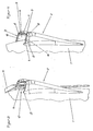
- the seat belt devices shown in the figures are on the Interior wall 1 of a motor vehicle, preferably in the area of one of the Pillars of the body arranged.
- the seat belt device has one Holding bag 2, which is in an approximately spherical, at least from the top below, the area is convex in the interior of the motor vehicle the interior wall 1 is arranged.
- Both the holding bag 2 and the Interior wall 1 are formed as an injection molded plastic part, in which Figures 1 to 6 and 8 to 9 holding bag 2 and interior wall 1 as an integral Component are formed and the holding pocket 2 raised from the contour the interior wall 1 protrudes into the interior.
- FIG. 7 there are holding pocket 2 and interior wall 1 from several assembled parts.
- the holding bag 2 is arranged sunk into the contour of the interior wall 1.
- the holding pocket 2 has two approximately vertically extending guide grooves 3 with mutually facing groove openings 4.
- the guide grooves 3 are open at their upper end and form insertion openings 5. At the lower The guide grooves 3 are closed at the ends by stop walls 6.
- the webbing 11 has one free end in the lower interior area attached in a manner not shown and extends in the unused Condition over the holding bag 2 in the upper interior area, where it is in also not shown way to a deflection fitting Belt retractor is guided.
- the tongue 10 consists of a in the direction of extension of the webbing 11 slightly S-shaped plate-like tongue part 12 made of metal, the one at its upper end a transversely to the longitudinal extension of the Webbing 11 extending, continuous slot 13 of the same length as the width of the webbing 11 has.
- the entire upper end area including the slot walls is with a plastic coating 14th Mistake.
- the tongue part 12 has a through opening 15 with which the Lock tongue 10 in the used state of the seat belt device in one Belt buckle, not shown, can be locked.
- the webbing 11 is coming from the upper interior area Side of the interior introduced into the slot 13 and extends the side of the tongue part 12 facing away from the interior further to the lower Indoors.
- the Lock tongue 10 Since the webbing retractor tensioned the webbing 11 and the Lock tongue 10 is slidably disposed on the webbing, the Lock tongue 10 inserted into the holding pocket 2 in the storage position and the webbing 11 with its areas above and below the lock tongue with slight pre-tension on the interior wall 1 kept in contact so that neither the tongue 10 nor the webbing 11 on the interior wall 1 excited by vibrations during driving of the motor vehicle can strike.
- the lock tongue of the beads 9 can still be in the holding pocket be resiliently urged against the groove walls 8.
Landscapes
- Engineering & Computer Science (AREA)
- Mechanical Engineering (AREA)
- Automotive Seat Belt Assembly (AREA)
Abstract
Description
Durch diese Ausbildung wird im unbenutzten Zustand der Sicherheitsgurteinrichtung die Schlosszunge in der Haltetasche gehalten und kann insbesondere im Fahrbetrieb des Kraftfahrzeugs keine Klapper- und Anschlaggeräusche mehr erzeugen. Dies wird besonders sicher verhindert, wenn die Schlosszunge spielfrei in der Haltetasche gehalten wird.
- Figur 1
- eine perspektivischen Ansicht eines ersten Ausführungsbeispiels einer Sicherheitsgurteinrichtung
- Figur 2
- eine Vorderansicht der Sicherheitsgurteinrichtung nach Figur 1
- Figur 3
- eine perspektivische Seitenansicht der Sicherheitsgurteinrichtung nach Figur 1
- Figur 4
- eine perspektivische Seitenansicht der Haltetasche der Sicherheitsgurteinrichtung nach Figur 1
- Figur 5
- einen Schnitt entlang der Linie II - II in Figur 2
- Figur 6
- einen Schnitt entlang der Linie VI - VI in Figur 2
- Figur 7
- einen Querschnitt eines zweiten Ausführungsbeispiels einer Sicherheitsgurteinrichtung
- Figur 8
- einen Schnitt entlang der Linie VIII - VIII in Figur 2
- Figur 9
- einen Schnitt entlang der Linie IX - IX in Figur 2.
In die Haltetasche 2 ist im unbenutztem Zustand der Sicherheitsgurteinrichtung eine an einem Gurtband 11 angeordnete Schlosszunge 10 einführbar und wird dort klapperfrei gehalten.
- 1
- Innenraumwand
- 2
- Haltetasche
- 3
- Führungsnut
- 4
- Nutöffnung
- 5
- Einführöffnung
- 6
- Anschlagwand
- 7
- Nutwand
- 8
- Nutwand
- 9
- Wulst
- 10
- Schlosszunge
- 11
- Gurtband
- 12
- Zungenteil
- 13
- Schlitz
- 14
- Kunststoffbeschichtung
- 15
- Öffnung
- 16
- Nutgrund
Claims (16)
- Sicherheitsgurteinrichtung für ein Kraftfahrzeug, mit einem Gurtband, das mit einem freien Ende im unteren Innenraumbereich des Kraftfahrzeugs befestigt ist und sich im unbenutzten Zustand entlang einer Innenraumwand, insbesondere in einem Säulenbereich etwa senkrecht in den oberen Innenraumbereich erstreckt und dort über einen Umlenkbeschlag zu einem das Gurtband spannenden Gurtbandaufroller geführt ist, wobei im Bereich zwischen der Befestigung im unteren Innenraumbereich und dem Umlenkbeschlag eine plattenartige Schlosszunge größerer Breite als der Breite des Gurtbandes an dem Gurtband angeordnet ist, die mit einem Gurtschloss verbindbar ist, dadurch gekennzeichnet, dass an der Innenraumwand (1) eine Haltetasche (2) angeordnet ist, die zwei etwa senkrecht sich erstreckende, mit ihren Nutöffnungen (4) einander zugewandte Führungsnuten (3) aufweist, wobei der Abstand der Nutöffnungen (4) voneinander etwa der Breite des Gurtbandes (11) entspricht und die Schlosszunge (10) von deren Einführöffnungen (5) bildenden oberen Enden her bis zur Anlage an einem Anschlag in die Führungsnuten (3) einführbar ist.
- Sicherheitsgurteinrichtung nach Anspruch 1, dadurch gekennzeichnet, dass die Schlosszunge (10) an ihrem oberen Endbereich einen sich quer zur Längserstreckung des Gurtbandes (11) erstreckenden, durchgehenden Schlitz (13) etwa gleicher Länge wie der Breite des Gurtbandes (11) aufweist, durch den das Gurtband (11) verschiebbar geführt ist.
- Sicherheitsgurteinrichtung nach Anspruch 2, dadurch gekennzeichnet, dass bei in die Haltetasche (2) eingeführter Schlosszunge (10) das Gurtband (11) oberhalb des Schlitzes (13) innenraumseitig der Schlosszunge (10) zum Umlenkbeschlag und unterhalb des Schlitzes (13) innenraumabgewandt der Schlosszunge (10) zum unteren Innenraumbereich geführt ist.
- Sicherheitsgurteinrichtung nach einem der vorhergehenden Ansprüche, dadurch gekennzeichnet, dass der Abstand zwischen den Nutgründen (16) der Führungsnuten (3) etwa der Breite der Schlosszunge (10) entspricht.
- Sicherheitsgurteinrichtung nach einem der vorhergehenden Ansprüche, dadurch gekennzeichnet, dass der Anschlag zur Anlage der Schlosszunge durch eine Verringerung der Nutbreite an den den Einführöffnungen entgegengesetzten Enden der Führungsnuten gebildet ist.
- Sicherheitsgurteinrichtung nach einem der Ansprüche 1 bis 4, dadurch gekennzeichnet, dass der Anschlag zur Anlage der Schlosszunge (10) durch die die unteren Enden der Führungsnuten (3) ganz oder teilweise verschießenden Anschlagwände (6) gebildet ist.
- Sicherheitsgurteinrichtung nach einem der vorhergehenden Ansprüche, dadurch gekennzeichnet, dass die von der Innenraumwand (1) beabstandeten Nutwände (7) der Führungsnuten (3) zumindest in ihren den Einführöffnungen (5) näheren Bereichen etwa senkrecht zur Innenraumwand (1) elastisch federnd ausgebildet sind.
- Sicherheitsgurteinrichtung nach Anspruch 7, dadurch gekennzeichnet, dass zumindest eine der Nutwände (7) einer Führungsnut (3) mit einem zu der anderen Nutwand (8) hin hervorstehenden Wulst (9) versehen ist.
- Sicherheitsgurteinrichtung nach Anspruch 8, dadurch gekennzeichnet, dass der Wulst (9) nahe der Einführöffnung (5) der Führungsnut (3) ausgebildet ist.
- Sicherheitsgurteinrichtung nach einem der vorhergehenden Ansprüche, dadurch gekennzeichnet, dass die Haltetasche (2) in einem etwa konvex von einem oberen zu einem unteren Bereich des Innenraums sich erstreckenden, in den Innenraum des Kraftfahrzeugs ragenden Bereich der Innenraumwand (1) angeordnet ist.
- Sicherheitsgurtanordnung nach einem der vorhergehenden Ansprüche, dadurch gekennzeichnet, dass die Haltetasche als separates Bauteil auf der Innenraumwand befestigt ist.
- Sicherheitsgurteinrichtung nach Anspruch 11, dadurch gekennzeichnet, dass die Haltetasche ein Kunststoffteil, insbesondere ein Spritzguss-Kunststoffteil ist.
- Sicherheitsgurtanordnung nach einem der Ansprüche 1 bis 10, dadurch gekennzeichnet, dass die Haltetasche (2) ein integrales Bauteil der Innenraumwand (1) ist.
- Sicherheitsgurteinrichtung nach einem der vorhergehenden Ansprüche, dadurch gekennzeichnet, dass die Innenraumwand (1) ein Kunststoffteil, insbesondere ein Spritzguss-Kunststoffteil ist.
- Sicherheitsgurteinrichtung nach einem der vorhergehenden Ansprüche, dadurch gekennzeichnet, dass die Haltetasche (2) erhaben von der Kontur der Innenraumwand (1) hervorstehend angeordnet ist.
- Sicherheitsgurteinrichtung nach einem der Ansprüche 1 bis 14, dadurch gekennzeichnet, dass die Haltetasche (2) in die Kontur der Innenraumwand (1) versenkt, insbesondere vollständig versenkt angeordnet ist.
Applications Claiming Priority (2)
| Application Number | Priority Date | Filing Date | Title |
|---|---|---|---|
| DE10226052 | 2002-06-12 | ||
| DE2002126052 DE10226052A1 (de) | 2002-06-12 | 2002-06-12 | Sicherheitsgurteinrichtung |
Publications (3)
| Publication Number | Publication Date |
|---|---|
| EP1371531A2 true EP1371531A2 (de) | 2003-12-17 |
| EP1371531A3 EP1371531A3 (de) | 2004-12-15 |
| EP1371531B1 EP1371531B1 (de) | 2007-10-17 |
Family
ID=29557778
Family Applications (1)
| Application Number | Title | Priority Date | Filing Date |
|---|---|---|---|
| EP20030012752 Expired - Lifetime EP1371531B1 (de) | 2002-06-12 | 2003-06-05 | Sicherheitsgurteinrichtung |
Country Status (3)
| Country | Link |
|---|---|
| EP (1) | EP1371531B1 (de) |
| DE (2) | DE10226052A1 (de) |
| ES (1) | ES2294217T3 (de) |
Cited By (7)
| Publication number | Priority date | Publication date | Assignee | Title |
|---|---|---|---|---|
| EP2072350A1 (de) * | 2007-12-17 | 2009-06-24 | Skoda Auto A.S. | Klinkehalter eines Sicherheitsgurts |
| JP2014019324A (ja) * | 2012-07-19 | 2014-02-03 | Mitsubishi Automob Eng Co Ltd | 車両用シートベルト装置 |
| JP2014168988A (ja) * | 2013-03-01 | 2014-09-18 | Toyota Auto Body Co Ltd | シートベルト保持用ベゼル、シートベルト用ガイドユニット及びシートベルト装置 |
| JP2014184791A (ja) * | 2013-03-22 | 2014-10-02 | Suzuki Motor Corp | シートベルトのタング保持構造 |
| US20190023221A1 (en) * | 2017-07-20 | 2019-01-24 | Toyota Motor Engineering & Manufacturing North America, Inc. | Vehicles including pillar garnish assemblies with seat belt latch-receiving structures |
| US20190217811A1 (en) * | 2018-01-12 | 2019-07-18 | Ford Global Technologies, Llc | Seat belt having embedded pocket for storing connector tongue |
| US11999314B1 (en) * | 2023-01-13 | 2024-06-04 | Honda Motor Co., Ltd. | Seat belt structure for a vehicle |
Families Citing this family (2)
| Publication number | Priority date | Publication date | Assignee | Title |
|---|---|---|---|---|
| DE102014017516B4 (de) | 2014-11-27 | 2018-01-11 | Audi Ag | Sicherheitsgurt für ein Kraftfahrzeug |
| DE102016202710B4 (de) * | 2016-02-22 | 2022-07-28 | Volkswagen Aktiengesellschaft | Innenraumverkleidung für ein Fahrzeug und Fahrzeug mit derselben |
Family Cites Families (4)
| Publication number | Priority date | Publication date | Assignee | Title |
|---|---|---|---|---|
| FR2232210A5 (en) * | 1973-05-29 | 1974-12-27 | Caron Georges | Method of assembling seats using several blocks - uses complementary male and female elements at edges of blocks |
| US3941419A (en) * | 1974-11-21 | 1976-03-02 | General Motors Corporation | Buckle component for a vehicle occupant restraint belt system |
| JPS558583Y2 (de) * | 1975-09-08 | 1980-02-26 | ||
| DE19642689C1 (de) * | 1996-10-16 | 1997-11-27 | Daimler Benz Ag | Sicherheitsgurt für Fahrzeugsitze |
-
2002
- 2002-06-12 DE DE2002126052 patent/DE10226052A1/de not_active Withdrawn
-
2003
- 2003-06-05 EP EP20030012752 patent/EP1371531B1/de not_active Expired - Lifetime
- 2003-06-05 DE DE50308390T patent/DE50308390D1/de not_active Expired - Lifetime
- 2003-06-05 ES ES03012752T patent/ES2294217T3/es not_active Expired - Lifetime
Cited By (7)
| Publication number | Priority date | Publication date | Assignee | Title |
|---|---|---|---|---|
| EP2072350A1 (de) * | 2007-12-17 | 2009-06-24 | Skoda Auto A.S. | Klinkehalter eines Sicherheitsgurts |
| JP2014019324A (ja) * | 2012-07-19 | 2014-02-03 | Mitsubishi Automob Eng Co Ltd | 車両用シートベルト装置 |
| JP2014168988A (ja) * | 2013-03-01 | 2014-09-18 | Toyota Auto Body Co Ltd | シートベルト保持用ベゼル、シートベルト用ガイドユニット及びシートベルト装置 |
| JP2014184791A (ja) * | 2013-03-22 | 2014-10-02 | Suzuki Motor Corp | シートベルトのタング保持構造 |
| US20190023221A1 (en) * | 2017-07-20 | 2019-01-24 | Toyota Motor Engineering & Manufacturing North America, Inc. | Vehicles including pillar garnish assemblies with seat belt latch-receiving structures |
| US20190217811A1 (en) * | 2018-01-12 | 2019-07-18 | Ford Global Technologies, Llc | Seat belt having embedded pocket for storing connector tongue |
| US11999314B1 (en) * | 2023-01-13 | 2024-06-04 | Honda Motor Co., Ltd. | Seat belt structure for a vehicle |
Also Published As
| Publication number | Publication date |
|---|---|
| DE10226052A1 (de) | 2003-12-24 |
| EP1371531B1 (de) | 2007-10-17 |
| ES2294217T3 (es) | 2008-04-01 |
| DE50308390D1 (de) | 2007-11-29 |
| EP1371531A3 (de) | 2004-12-15 |
Similar Documents
| Publication | Publication Date | Title |
|---|---|---|
| DE19717666B4 (de) | Gurtintegralsitz eines Kraftfahrzeugs mit einer Rückenlehne, einer Kopfstütze und einer Gurtführungseinrichtung | |
| DE4129312C2 (de) | Schultergurteinstellvorrichtung | |
| EP0158990B1 (de) | Kraftfahrzeugsitz | |
| DE2316353A1 (de) | Verschlussteil fuer kraftfahrzeug-sicherheitsgurt | |
| DE10100805A1 (de) | Fahrzeugsitzaufbau | |
| DE112012002030T5 (de) | Insassenrückhaltesystem | |
| DE3425669A1 (de) | Verriegelungsvorrichtung fuer eine hintersitz-rueckenlehne | |
| DE3636912C2 (de) | Rückenlehne für einen Fahrzeugsitz | |
| EP0903268A1 (de) | Kopf-Seitengassack-Rückhaltesystem für Fahrzeuginsassen | |
| DE202017103693U1 (de) | Innenüberbrückungsnothandgriff zur Türfreigabe | |
| EP0609890A1 (de) | Kindersicherheitssitz für Fahrzeuge | |
| DE3336952A1 (de) | Druckknopfschloss, insbesondere fuer verschlussklappen von handschuhfaechern in kraftfahrzeugen | |
| EP1371531A2 (de) | Sicherheitsgurteinrichtung | |
| DE1505481B2 (de) | Fahrzeugsitz | |
| DE3151019C2 (de) | Vorrichtung zum Befestigen des oberen Umlenkbeschlages für einen Dreipunktsicherheitsgurt an der Karosserie eines Kraftfahrzeuges | |
| EP1274612B1 (de) | Befestigungsanordnung für sicherheitsgurtaufroller mit verstärkungsplatte | |
| EP0482168B1 (de) | Schocksicherer sicherheitsgurtverschluss | |
| DE3012754C2 (de) | Vorrichtung zum Verbinden des Schultergurtbandes eines Sicherheitsgurtes mit einem Träger, insbesondere einem Tür- oder Fensterholm eines Kraftfahrzeuges | |
| DE19944478A1 (de) | Gurtschloßanordnung für ein Insassenrückhaltesystem | |
| EP3401160B1 (de) | Gurtspanner | |
| DE102022114415A1 (de) | Messer | |
| DE112006001537T5 (de) | Zungenverriegelnde lösbare Verankerung | |
| DE8327221U1 (de) | Gurtschloß für ein Sicherheitsgurtsystem | |
| DE3421564A1 (de) | Verriegelungsvorrichtung fuer das sitzteil eines hintersitzes | |
| DE69816466T2 (de) | Sitzgurtschnalle |
Legal Events
| Date | Code | Title | Description |
|---|---|---|---|
| PUAI | Public reference made under article 153(3) epc to a published international application that has entered the european phase |
Free format text: ORIGINAL CODE: 0009012 |
|
| AK | Designated contracting states |
Kind code of ref document: A2 Designated state(s): AT BE BG CH CY CZ DE DK EE ES FI FR GB GR HU IE IT LI LU MC NL PT RO SE SI SK TR |
|
| AX | Request for extension of the european patent |
Extension state: AL LT LV MK |
|
| PUAL | Search report despatched |
Free format text: ORIGINAL CODE: 0009013 |
|
| AK | Designated contracting states |
Kind code of ref document: A3 Designated state(s): AT BE BG CH CY CZ DE DK EE ES FI FR GB GR HU IE IT LI LU MC NL PT RO SE SI SK TR |
|
| AX | Request for extension of the european patent |
Extension state: AL LT LV MK |
|
| 17P | Request for examination filed |
Effective date: 20050225 |
|
| AKX | Designation fees paid |
Designated state(s): DE ES FR GB |
|
| 17Q | First examination report despatched |
Effective date: 20061013 |
|
| GRAP | Despatch of communication of intention to grant a patent |
Free format text: ORIGINAL CODE: EPIDOSNIGR1 |
|
| GRAS | Grant fee paid |
Free format text: ORIGINAL CODE: EPIDOSNIGR3 |
|
| GRAA | (expected) grant |
Free format text: ORIGINAL CODE: 0009210 |
|
| AK | Designated contracting states |
Kind code of ref document: B1 Designated state(s): DE ES FR GB |
|
| REG | Reference to a national code |
Ref country code: GB Ref legal event code: FG4D Free format text: NOT ENGLISH |
|
| GBT | Gb: translation of ep patent filed (gb section 77(6)(a)/1977) |
Effective date: 20071017 |
|
| REF | Corresponds to: |
Ref document number: 50308390 Country of ref document: DE Date of ref document: 20071129 Kind code of ref document: P |
|
| ET | Fr: translation filed | ||
| REG | Reference to a national code |
Ref country code: ES Ref legal event code: FG2A Ref document number: 2294217 Country of ref document: ES Kind code of ref document: T3 |
|
| PLBE | No opposition filed within time limit |
Free format text: ORIGINAL CODE: 0009261 |
|
| STAA | Information on the status of an ep patent application or granted ep patent |
Free format text: STATUS: NO OPPOSITION FILED WITHIN TIME LIMIT |
|
| 26N | No opposition filed |
Effective date: 20080718 |
|
| REG | Reference to a national code |
Ref country code: GB Ref legal event code: 732E Free format text: REGISTERED BETWEEN 20090219 AND 20090225 |
|
| REG | Reference to a national code |
Ref country code: GB Ref legal event code: 732E Free format text: REGISTERED BETWEEN 20090305 AND 20090311 |
|
| REG | Reference to a national code |
Ref country code: GB Ref legal event code: 732E Free format text: REGISTERED BETWEEN 20091029 AND 20091104 |
|
| REG | Reference to a national code |
Ref country code: GB Ref legal event code: 732E Free format text: REGISTERED BETWEEN 20091105 AND 20091111 |
|
| REG | Reference to a national code |
Ref country code: DE Ref legal event code: R081 Ref document number: 50308390 Country of ref document: DE Owner name: GM GLOBAL TECHNOLOGY OPERATIONS LLC (N. D. GES, US Free format text: FORMER OWNER: GM GLOBAL TECHNOLOGY OPERATIONS, INC., DETROIT, MICH., US Effective date: 20110323 |
|
| PGFP | Annual fee paid to national office [announced via postgrant information from national office to epo] |
Ref country code: ES Payment date: 20120726 Year of fee payment: 10 |
|
| PGFP | Annual fee paid to national office [announced via postgrant information from national office to epo] |
Ref country code: DE Payment date: 20130529 Year of fee payment: 11 Ref country code: GB Payment date: 20130605 Year of fee payment: 11 |
|
| PGFP | Annual fee paid to national office [announced via postgrant information from national office to epo] |
Ref country code: FR Payment date: 20130624 Year of fee payment: 11 |
|
| REG | Reference to a national code |
Ref country code: DE Ref legal event code: R119 Ref document number: 50308390 Country of ref document: DE |
|
| GBPC | Gb: european patent ceased through non-payment of renewal fee |
Effective date: 20140605 |
|
| REG | Reference to a national code |
Ref country code: DE Ref legal event code: R119 Ref document number: 50308390 Country of ref document: DE Effective date: 20150101 |
|
| REG | Reference to a national code |
Ref country code: FR Ref legal event code: ST Effective date: 20150227 |
|
| PG25 | Lapsed in a contracting state [announced via postgrant information from national office to epo] |
Ref country code: DE Free format text: LAPSE BECAUSE OF NON-PAYMENT OF DUE FEES Effective date: 20150101 |
|
| PG25 | Lapsed in a contracting state [announced via postgrant information from national office to epo] |
Ref country code: GB Free format text: LAPSE BECAUSE OF NON-PAYMENT OF DUE FEES Effective date: 20140605 Ref country code: FR Free format text: LAPSE BECAUSE OF NON-PAYMENT OF DUE FEES Effective date: 20140630 |
|
| REG | Reference to a national code |
Ref country code: ES Ref legal event code: FD2A Effective date: 20150724 |
|
| PG25 | Lapsed in a contracting state [announced via postgrant information from national office to epo] |
Ref country code: ES Free format text: LAPSE BECAUSE OF NON-PAYMENT OF DUE FEES Effective date: 20140606 |