EP1369752A2 - Bilderzeugungsgerät mit einer Reinigungsklinge - Google Patents
Bilderzeugungsgerät mit einer Reinigungsklinge Download PDFInfo
- Publication number
- EP1369752A2 EP1369752A2 EP03012161A EP03012161A EP1369752A2 EP 1369752 A2 EP1369752 A2 EP 1369752A2 EP 03012161 A EP03012161 A EP 03012161A EP 03012161 A EP03012161 A EP 03012161A EP 1369752 A2 EP1369752 A2 EP 1369752A2
- Authority
- EP
- European Patent Office
- Prior art keywords
- image carrier
- image
- cleaning
- cleaning blade
- drum
- Prior art date
- Legal status (The legal status is an assumption and is not a legal conclusion. Google has not performed a legal analysis and makes no representation as to the accuracy of the status listed.)
- Granted
Links
Images


Classifications
-
- G—PHYSICS
- G03—PHOTOGRAPHY; CINEMATOGRAPHY; ANALOGOUS TECHNIQUES USING WAVES OTHER THAN OPTICAL WAVES; ELECTROGRAPHY; HOLOGRAPHY
- G03G—ELECTROGRAPHY; ELECTROPHOTOGRAPHY; MAGNETOGRAPHY
- G03G21/00—Arrangements not provided for by groups G03G13/00 - G03G19/00, e.g. cleaning, elimination of residual charge
- G03G21/0005—Arrangements not provided for by groups G03G13/00 - G03G19/00, e.g. cleaning, elimination of residual charge for removing solid developer or debris from the electrographic recording medium
- G03G21/0011—Arrangements not provided for by groups G03G13/00 - G03G19/00, e.g. cleaning, elimination of residual charge for removing solid developer or debris from the electrographic recording medium using a blade; Details of cleaning blades, e.g. blade shape, layer forming
-
- G—PHYSICS
- G03—PHOTOGRAPHY; CINEMATOGRAPHY; ANALOGOUS TECHNIQUES USING WAVES OTHER THAN OPTICAL WAVES; ELECTROGRAPHY; HOLOGRAPHY
- G03G—ELECTROGRAPHY; ELECTROPHOTOGRAPHY; MAGNETOGRAPHY
- G03G2221/00—Processes not provided for by group G03G2215/00, e.g. cleaning or residual charge elimination
- G03G2221/0026—Cleaning of foreign matter, e.g. paper powder, from imaging member
- G03G2221/0068—Cleaning mechanism
- G03G2221/0089—Mechanical
Definitions
- the present invention relates to an image forming apparatus for forming a toner image on an image carrier with an electrophotographic process and transferring the toner image to a sheet or recording medium either directly or via an intermediate image transfer body. Also, the present invention relates to a developing device included in an image forming apparatus and using a plurality of developing rollers arranged side by side in the direction of rotation of an image carrier and operable with a two-ingredient type developer, i.e., a toner and carrier mixture, and a cleaning device also included in the image forming apparatus for removing residual toner and impurities left on the image carrier with a cleaning blade.
- a developing device included in an image forming apparatus and using a plurality of developing rollers arranged side by side in the direction of rotation of an image carrier and operable with a two-ingredient type developer, i.e., a toner and carrier mixture
- a cleaning device also included in the image forming apparatus for removing residual toner and impurities left on the image carrier with a
- Toner with a small grain size enhances image quality, but is defectively charged due to an increase in the carrier coating ratio of the toner, as known in the art.
- another problem with toner having a small grain size is that the carrier easily deposits on the image carrier.
- Japanese Patent Laid-Open Publication No. 6-51628 and Japanese Patent No. 2,930,812 each define a specific linear velocity of an image carrier and that of a developing roller by using a magnet roller whose magnetic force is weak.
- developing ability available with the above documents is short because use is made of only one developing roller.
- the flux density of a main pole for development included in a developing roller may be increased, as proposed in the past.
- This scheme is directed mainly toward a developing device of the type using a single developing roller. If such a scheme is applied to a developing device of the type using a plurality of developing rollers, then it effects the flow of a developer between the developing rollers and causes an excessive amount of developer to be conveyed, resulting in overflow and other troubles.
- the intense magnetic force of the main pole intensifies even a magnetic force at the rear of the main pole, preventing the developer from parting from the downstream developing roller. Consequently, the developer moves in accordance with the rotation of the downstream developing roller and again reaches the upstream developing roller. This is also apt to bring about the smearing of an image and the overflow of the developer. It is therefore difficult to obviate carrier deposition on the image carrier by intensifying the magnetic force.
- a cylindrical magnet roller by combining magnets each forming a particular pole and used a rare earth magnet for one of the magnets forming the main pole.
- the rare earth magnet with an intense magnetic force caused a developer to follow the rotation of a developing roller and overflow.
- Japanese Patent No. 2,545,601 and Japanese Patent Laid-Open Publication No. 2000-81789 each also propose a cylindrical magnet roller in which a rare earth magnet is buried at the main pole for development.
- the rare earth magnet is 1.15 mm long or thick in the radial direction of the roller and 5 mm long or wide in the circumferential direction of the roller.
- the length in the radial direction is small, the length in the circumferential direction is great and causes the intense magnetic force to effect the other poles, again resulting in the problem stated above.
- Laid-Open Publication No. 2000-81789 although the rare earth magnet is as short or thin as 3 mm in the radial direction of the roller, it is as long or wide as 4 mm in the circumferential direction of the roller, also resulting in the above problem.
- the pressure of the cleaning blade acting on the image carrier may be lowered or canceled while the image carrier may be moved in the reverse direction, as proposed in, e.g., Japanese Patent Laid-Open Publication Nos. 2000-155514 (column "0030, FIG. 5) and 05-119687 (column "0011", FIG. 1). Further, the image carrier may be again moved in the forward direction after the reverse movement and then stopped, as taught in, e.g., Japanese Patent Laid-Open Publication No. 07-175394. In any case, the reverse rotation of the image carrier is used to cancel pressure acting on the toner and impurities caught by the edge of the cleaning blade, thereby promoting the removal.
- the cleaning device taught in, e.g., Laid-Open Publication No. 05-119687 mentioned earlier includes a seal positioned at the inlet of the cleaning device where toner is apt to drop and smear surrounding.
- this type of cleaning device when the image carrier is moved in the reverse direction, it is possible to efficiently remove the impurities caught by the edge of the cleaning blade by increasing the amount of reverse movement in both of the configuration of Laid-Open Publication No. 2000-155514 lacking a seal and the configuration of Laid-Open Publication No. 05-119687 including a seal.
- the portion of the image carrier facing the cleaning device is sometimes moved over the inlet of the cleaning device with the result that the toner deposited on part of the image carrier moved over the inlet drops due to gravity or friction acting between it and the seal.
- the toner thus dropped from the image carrier accumulates on such members and therefore smears sheets or renders the output of the image density sensor erroneous.
- the toner deposited on the peeler varies frictional resistance between the peeler and a sheet to thereby bring about defective sheet separation or smears the sheet.
- the toner deposited on the image density sensor makes the output of the sensor differ from the actual image density.
- toner deposits more on the portion of the image carrier facing the cleaning member than on the other portion of the drum. Therefore, when the portion facing the cleaning member moves over the inlet of the cleaning device, a large amount of toner drops and makes the above problem more serious.
- the toner left on the image carrier can be removed more easily if the surface of the image carrier has a smaller coefficient of friction. Stated another way, the removal efficiency decreases with an increase in the coefficient of friction. Particularly, we experimentally found that cleaning ability was lowered when the coefficient of friction was 0.2 or below, as described in copending U.S. Patent Application Serial No. 10/418,111 filed on April 18, 2003.
- the coefficient of friction has influence on friction energy acting between the cleaning blade and the image carrier. If friction energy is high, then toner is apt to melt and adhere to the image carrier and thereby degrade the removal efficiency of the cleaning blade. This is particularly true when toner with a small grain size is used for enhancing resolution, because such toner has small thermal capacity.
- the toner adhered to the image carrier and unable to be removed brings about filming stated earlier and deteriorates characteristics on the surface of the image carrier throughout the consecutive image forming steps.
- Filming is effected by the hardness of the surface of the image carrier as well. More specifically, when surface hardness is low, the cleaning blade grinds the surface of the image carrier and refreshes it, so that filming occurs little. However, when the image carrier is formed of amorphous silicone (a-Si) implementing a hard surface that wears little or is provided with a surface layer containing inorganic grains, it is difficult for the cleaning blade to grind the surface and therefore obviate filming.
- a-Si amorphous silicone
- the cleaning blade is caused to warp in the opposite direction by the image carrier moving in the reverse direction, allowing the toner and impurities to be released from the edge of the cleaning blade.
- the image carrier is again moved in the forward direction, it is likely that the toner and impurities so released are again caught by the edge of the cleaning blade. It is therefore difficult to fully prevent the cleaning blade from catching the toner and impurities. This is particularly true when the cleaning blade contacts the image carrier at the downstream edge of its end face, as determined by experiments.
- An image forming apparatus including a cleaning device for removing toner, paper dust and other impurities left on an image carrier after image transfer with a cleaning member is disclosed.
- the cleaning member contacts the surface of the image carrier with variable pressure and remains, about the time when the image carrier stops moving after image formation, in contact with the surface with pressure lower than pressure capable of scrapping off the impurities.
- the image carrier is driven in a reverse direction opposite to a forward direction assigned to image formation, stopped, and again moved in the forward direction and then in the reverse direction at least one time.
- the developing device includes two developing rollers 1 and 2 and is therefore superior in developing ability than a developing device including a single developing roller.
- the rotation speed of the rollers 1 and 2 increases to thereby increase a centrifugal force acting on the carrier of a developer, as stated earlier.
- the carrier deposits on an image carrier, not shown, included in the image forming apparatus.
- the flux density of a main magnetic pole for development when the flux density of a main magnetic pole for development is increased, it effects the flow of the developer between the developing rollers 1 and 2 and causes an excessive amount of developer to be conveyed, resulting in the overflow of the developer.
- the flux density of the main pole disposed in the downstream developing roller 2 when the flux density of the main pole disposed in the downstream developing roller 2 is increased, it scoops up the developer even via the gap between the developing rollers 1 and 2. Consequently, an excessive amount of developer deposits on the developing rollers 1 and 2 and brings about various problems including the smearing of an image.
- the intense magnetic force of the main pole intensifies even a magnetic force positioned at the rear of the main pole, preventing the developer from parting from the developing roller 2. Consequently, the developer moves in accordance with the rotation of the developing roller 2, as indicated by an arrow in FIG. 1, and again reaches the upstream developing roller 1. This is also apt to bring about the smearing of an image and the overflow of the developer. It is therefore difficult to obviate carrier deposition on the image carrier by intensifying the magnetic force.
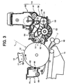
- an image forming apparatus including a developing device and embodying the present invention is shown and implemented as a laser copier by way of example.
- the laser copier includes a casing 10 and a photoconductive drum or image carrier 12 disposed in the casing 10 and rotatable clockwise, as viewed in FIG. 2.
- a charger 13 Arranged around the drum 12 are a charger 13, a developing device 14, an image transferring and sheet conveying device 15, a cleaning device 16, and a quenching lamp or discharging device 17.
- a laser writing unit 18 is positioned in the upper portion of the casing 10 and includes a laser diode or similar light source 20 that emits a laser beam L, a polygonal mirror 21, a motor 22 for driving the polygonal mirror 21, and optics 23 including an f ⁇ lens.
- a fixing device 25 is positioned at the left-hand side of the cleaning device 16 and includes a heat roller 26 accommodating a heater and a press roller 27 pressed against the heat roller 26.
- a scanner or document reading device 30 includes a light source 31, a plurality of mirrors 32, a lens 33, and a CCD (Charge Coupled Device) image sensor or similar image sensor 34.
- CCD Charge Coupled Device
- a duplex copy unit 35 is arranged in the lower portion of the casing 10 and includes a refeed path 37 merging into a path 36, which extends to a position beneath the drum 12.
- a glass platen 40 is mounted on the top of the casing 10.
- An ADF (Automatic Document Feeder) 41 is hinged to the top of the casing 10 in such a manner as to selectively cover or uncover the glass platen 40.
- the casing 10 of the copier is mounted on a table 43 that accommodates a plurality of sheet cassettes 44 stacked one above the other.
- Pickup rollers 45 each are assigned to one of the sheet cassettes 44 and pay out a sheet from the associated sheet cassette toward the path 46.
- a plurality of rollers 47 are arranged on the path 46.
- the operator of the copier stacks desired documents on the ADF 41 or opens the ADF 41 and then lays a desired document on the glass platen 40. Subsequently, when the operator presses a start switch, not shown, the scanner 30 reads a document conveyed to the glass platen by the ADF 41 or a document laid on the glass platen 40 by hand on a pixel basis. At the same time, one of the pickup rollers 45 assigned to designated one of the sheet cassettes 44 is caused to pay out one sheet from the sheet cassette to the path 46. The sheet thus paid out is conveyed by the rollers 47 to a registration roller 48. The registration roller 48 once stops the sheet and then conveys it to the position beneath the drum 12 in synchronism with the rotation of the drum 12.
- the drum 12 starts rotating clockwise, as viewed in FIG. 1.
- the charger 1 uniformly charges the surface of the drum 12 in rotation.
- the laser writing device 18 scans the charged surface of the drum 12 with the laser beam L in accordance with image data output from the scanner 30, thereby forming a latent image representative of the document image on the drum 12.
- the developing device 14 develops the latent image with toner to thereby produce a corresponding toner image.
- the image transferring and sheet conveying device 15 transfers the toner image thus formed on the drum 12 to the sheet reached the position beneath the drum 12.
- the cleaning device 16 removes toner left on the drum 12 after such image transfer.
- the quenching lamp 17 discharges the cleaned surface of the drum 12 for thereby preparing it for the next image forming cycle.
- the sheet, carrying the toner image transferred from the drum 12, is conveyed to the fixing device 25 by the sheet conveying device 15.
- the heat roller 26 and press roller 27 fix the toner image on the sheet with heat and pressure.
- the sheet come out of the fixing device 25 is driven out of the copier to a tray, not shown, mounted on the casing 10 via the outlet path 38.
- the sheet, carrying the toner image on one side thereof, is steered toward the duplex copy unit 35 via a turn path 39 and again conveyed to the position beneath the drum 12. At this position, another toner image formed on the drum 12 is transferred to the other side of the sheet. Subsequently, the sheet or duplex copy may be driven out to the tray mentioned earlier.
- FIG. 3 shows the developing device 14 in detail.
- the developing device 14 is generally made up of a tank 50 and a hopper 60.
- the tank 50 includes a case 59 accommodating a first and a second developing roller 51 and 52, a paddle wheel 53, an agitator 54 implemented as a roller, a screw 55, a separator 56, a doctor blade 57, and a toner content sensor 58.
- a two-ingredient type developer, i.e., a toner and carrier mixture is stored in the case 59.
- the first and second developing rollers 51 and 52 are positioned side by side in the direction of rotation of the drum 12.
- the first developing roller 51 is made up of a hollow, cylindrical sleeve 70 and a multiple-pole magnet roller 71 held stationary within the sleeve 70.
- the magnet roller 71 has five magnets a , b , c , d and e adhered to a single shaft 72, as illustrated.
- the five magnets a through e comprise a sectorial, resin-coupled magnet based on ferrite each and are separate from each other to form five magnetic poles P1 through P5.
- the second developing roller 52 downstream of the first developing roller 51 in the direction of rotation of the drum 12 is made up of a hollow, cylindrical sleeve 74 and a multiple-pole magnet 75 held stationary within the sleeve 74.
- the magnet roller 75 has three first magnets f , g and h adhered to a single shaft 76.
- the magnets f through h comprise a sectorial, resin-coupled magnet based on ferrite each and are separate from each other to form three magnetic poles P1 through P3.
- a second magnet m is buried in the first magnet f , which forms the pole P1, and implemented as an R-Fe-B or similar rare earth magnet.
- the first magnet f has a length or thickness T in the radial direction of the roller 52 and has a length or width W in the circumferential direction of the roller 52 and is tightly fitted in a groove also having a width W and adhered to the walls of the groove.
- the length T is selected to be 3 mm, which is 15 % of the outside diameter L of the sleeve 74, while the length W is selected to be 4 mm that is 20 % of the above outside diameter.
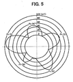
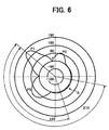
- FIGS. 5 and 6 respectively show the flux density waveform of the first developing roller 51 and the flux density waveform of the second developing roller 52.
- the main poles P1 of the two developing rollers 51 and 52 are positioned in the vicinity of the drum 12.
- the main pole P1 of the second developing roller 52 is implemented as a single pole and has a flux density of 120 mT or above in the radial direction of the sleeve 74, as measured on the surface of the sleeve 74.
- the flux density of the developing roller 52 is selected to be 15 mT or below, as measured on the surface of the sleeve 74 in the radial direction, between a position spaced by 150° downstream from the main pole P1 and a position spaced by 210° downstream from the same.
- a gear-toothed toner replenishing member 61, a regulating plate 62 and an agitator 63 are disposed in the hopper 60.
- the hopper 60 stores fresh toner to be replenished to the case 59.
- the agitator 54 agitates the developer present in the case 59 while charging it by friction.
- the paddle wheel 53 in rotation scatters the developer upward.
- the flux density of the second developing roller 52 as measured on the surface of the sleeve 74 in the radial direction, is 15 mT or below, the developer so scattered upward deposits on the second developing roller 52 little, but deposits on the first developing roller 51.
- the developing roller deposited on the first developing roller 51 is conveyed by the sleeve 70 of the roller 51 while being metered by the doctor blade 57 to form a thin layer.
- the developer on the sleeve 70 rises in the form of brush chains with the result that the toner contained in the developer is transferred to the drum 12, developing a latent image carried on the drum 12.
- the developing device 14 using the two developing rollers 51 and 52 for development, achieves a wider developing zone and therefore higher developing ability than a developing device using a single developing roller, thereby promoting high-speed development.
- the agitator 63 is rotated to agitate the fresh toner while conveying it to the toner replenishing member 61.
- the toner replenishing member 61 in rotation causes the regulating plate 62 to oscillate, thereby replenish the fresh toner from the hopper 60 to the tank 50. This maintains the toner content of the developer substantially constant.
- the toner content sensor 58 mounted on the case 59 senses the toner content of the developer present in the case 59.
- the target toner sensor 58 is set on the basis of the density of a toner pattern or P pattern formed on the drum 12 and measured by a photosensor not shown.
- the toner deposited on the drum 12 is electrostatically transferred to a sheet by the image transferring device 15, about 10 % of the toner is left on the drum 12 as residual toner.
- the cleaning device 16 removes such residual toner from the drum 12 with a cleaning blade 65 and a brush roller 66.
- the toner thus removed from the drum 12 is collected in a tank 67 also included in the cleaning device 16.
- a screw 68 conveys the toner from the tank 67 to one side of the cleaning device 16.
- the residual toner is conveyed to a waste toner tank, not shown, via an outlet, not shown, formed in the cleaning device 16.
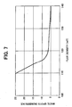
- FIG. 7 shows the results of experiments conducted to determine the mean number of white spots to appear on a sheet of size A4 by varying the flux density of the main pole P1 of the second developing roller 52, as measured on the surface of the sleeve 74 in the radial direction.
- the experiments were conducted by outputting a dot image, which is apt to suffer from carrier deposition, and feeding no current to the image transferring device 15, i.e., in a condition wherein portions where the carrier is deposited easily appear on a sheet as white spots.
- the number of white spots sharply increases as the flux density in the radial direction decreases below 120 mT.
- the number of white spots is only ten or less if the above flux density is 120 mT or above. It was experimentally found that if the number of white spots was ten or less, then defects ascribable to carrier deposition did not appear.
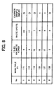
- FIG. 8 shows a relation between the magnetic force of the second developing roller 52, the number of white spots, and the smearing of an image ascribable to carrier drop, as determined by experiments.
- the flux density in the radial direction is 120 mT or above, it is likely that the developer is scooped up via the gap between the first and second developing rollers 51 and 52.
- the flux density, as measured on the surface of the sleeve 74 in the radial direction is selected to be 15 mT or below between the 150° point and the 210° point downstream of the main pole P1, as stated earlier, then the developer easily parts from the developing roller 52 between the above two points. This obviates the overflow of the developer ascribable to excessive scoop-up, a double image and other troubles.
- the main pole P1 of the second developing roller 52 is implemented as three poles including two auxiliary poles, the half-value width of the main pole and therefore the nip for development is reduced, enhancing image equality.
- the three-pole scheme causes the developer to rise even at the auxiliary poles, which do not contribute to development, and is therefore bring about carrier deposition due to the weak magnetic force of the auxiliary poles.
- the main pole is implemented as a single pole, the number of white spots remains ten or less at all times, obviating defects ascribable to carrier deposition.
- the illustrative embodiment realizes a high quality, reliable image forming apparatus.
- the printer generally 100, includes a photoconductive drum or image carrier 101.
- a charger 102 Arranged around the drum 101 are a charger 102, an optical writing unit represented by a light beam 103, a developing device 105 and a cleaning device 106 for executing an image forming process.
- the drum 101 is formed of amorphous silicon (a-Si) implementing high surface hardness and wearing little or is provided with a surface layer containing inorganic grains.
- the drum 101 has a coefficient of friction ⁇ of 0.2 or above, as measured on the surface of the drum 101.
- the charger 102 uniformly charges the surface of the drum 101 being rotated.
- the optical writing unit scans the charged surface of the drum 101 with the light beam 103 in accordance with image data, forming a latent image on the drum 101.
- the developing device 5 develops the latent image with toner for thereby producing a corresponding toner image.
- the toner image is then electrostatically transferred from the drum 101 to a sheet conveyed from a sheet feeding device not shown. Subsequently, the toner image is fixed on the sheet by a fixing device not shown.
- the illustrative embodiment is identical with the previous embodiment.
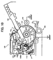
- the cleaning device 106 removes the toner and various impurities left on the drum 101. Subsequently, a quenching lamp, not shown, discharges the surface of the drum 101, as stated previously.
- the cleaning device 106 includes a unit 106A formed with an opening facing the drum 101.
- a cleaning brush 107 and a cleaning blade 108 are disposed in the unit 106A at the upstream side and downstream side, respectively, in the direction of rotation of the drum 101 and constantly held in contact with the drum 101.
- the cleaning blade 108 is formed of polyurethane
- the unit 106A further includes a coil 110, a seal 111, and a vent portion 106B.
- the coil 110 conveys the toner collected from the drum 101 to a pipe 109, so that the toner can be again used as recycled toner.
- the seal or sealing member 111 seals the inlet of the unit 106A located at the upstream side in the direction of rotation of the drum 101.
- An image density sensor 112 is responsive to the density of a toner image.
- a peeler 113 peels off a sheet from the drum 101.
- the cleaning brush 107 is made up of a rotatable roller and fibers implanted in the roller and having loop-like tips.
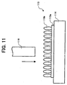
- the contact surface pressure of the cleaning brush 107, contacting the drum 10, is selected to be 50 gf/cm 2 or above. It is to be noted that the contact surface pressure corresponds to a reaction force generated in the cleaning brush 107 when the brush 107 is caused to bite into the drum 102 by a target amount. More specifically, as shown in FIG.
- a brush 115 is made up of a base cloth 115a and fibers 115b implanted in the base cloth 115a and is placed on a flat base 114, and that a rod 116, for example, has a flat surface having a unit area of 1 cm 2 and facing the brush 115 and bites into the brush 115 by a preselected amount of 1.5 mm. Then, the contact surface pressure refers to the resulting reaction force generated in the brush 115.
- the area of the flat surface, facing the brush 115 may be increased, in which case the resulting reaction force will be divided by the area of the flat surface to thereby produce a reaction force for a unit area.
- the drum 101 before the drum 101 starts rotating for repeating image formation after previous image formation or at the start-up of the printer 100, the drum 101 is caused to operate, stop, again operate, and then stop and wait for image formation. Such control over the drum 101 will be described hereinafter.
- the drum 101 Before rotation for image formation, the drum 101 is caused to move in the reverse direction, then move in the forward direction at least one time, and then move in the reverse direction at least one time. Stated another way, the drum 101 is stopped in the reversely moved position before the start of rotation for image formation. For example, after image formation, the drum 101 is caused to perform a sequence of reverse movement, forward movement, reverse movement and stop one time or a plurality of times.
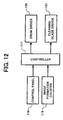
- FIG. 12 shows a control system included in the illustrative embodiment.
- the control system includes a controller 117 for executing the control over the drum 10 described above.
- a control panel 118 and an image formation counter 119 are connected to the input side of the controller 117 while a drum driver 120 and a cleaning blade driver 121 are connected to the output side of the controller 117.
- the controller 117 determines, based on the number of times of image formation input on the control panel 118 or the operation of a start switch, whether or not the rotation of the drum 101 has ended. More specifically, when the number of times of image formation is input on the control panel 118, the controller 117 determines whether or not image formation has ended on the basis of the count of the image formation counter 119, and executes rotation control if the answer is positive. On the other hand, when the start switch is operated to start the initialization of the printer 100, the controller 117 executes rotation control after the drum 101 has been brought to a stop.
- the amount of movement of the drum 101 is selected such that the surface of the drum 110, facing the cleaning blade 108, does not move over the seal 111; in the illustrative embodiment, the amount of movement corresponds to a period of time of 40 ms to 60 ms. More specifically, the amount of movement corresponding to such a period of time is about 10 mm to 15 mm although dependent on the peripheral speed. This protects the cleaning blade 108 from wear and breakage.
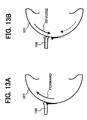
- FIG. 13A shows a specific condition wherein impurities are caught between the edge of the cleaning blade 108 and the drum 101 during the forward movement of the drum 101.
- FIG. 13B when the drum 101 is moved in the reverse direction, as stated above, the impurities are conveyed away from the edge of the cleaning blade 108.
- the edge of the cleaning blade 108 has been warped in opposite direction to warp occurred during the forward rotation of the drum 101 and therefore does not catch impurities. Further, the surface of the drum 101 does not move over the seal 111 during reverse movement, as stated earlier, so that the residual toner and impurities left on the drum 101 are prevented from being rubbed by the seal 111; otherwise, the residual toner and impurities would drop due to gravity or would come off due to rubbing.
- the illustrative embodiment is also characterized by the configuration of the cleaning blade 108 cooperating with the cleaning roller 107. Particularly, in the illustrative embodiment, when the drum 101 is moved in the reverse direction, the contact pressure of the cleaning blade 108 can be reduced, and the reduced contact pressure is variable, as will be described in detail hereinafter.
- the drum 101, cleaning device 106 and other process units for image formation are mounted on a cartridge removable from the apparatus body in a direction P.
- the cleaning blade 108 is held in contact with the drum 101 in the counter direction.
- the cleaning blade 108 is mounted on a bracket 108A pivotable about a fulcrum 108B.
- a solenoid or similar pressure adjusting means 122 is connected to the end of the bracket 108A remote from the cleaning blade 108.
- Biasing means not shown, constantly biases the cleaning blade 108 toward the drum 101 with preselected pressure that allows the blade 108 to scrape off impurities.
- the solenoid 122 When the solenoid 122 is energized, it moves the bracket 108A in the direction in which the cleaning blade 108 moves away from the drum 101. As a result, the cleaning blade 108 contacts the drum 101 with a pressure lower than the contact pressure necessary for scraping off impurities. Such reduced pressure of the cleaning blade 108 can be maintained in accordance with the direction of movement of the drum 101, which will be described specifically later.
- the solenoid 122 when the drum 101 is moved in the reverse direction about the time when it is caused to stop rotating after image formation, the solenoid 122 is energized to reduce the contact pressure of the cleaning blade 108. Consequently, even if impurities scraped off from the drum 101 remain caught by the cleaning blade 108 due to the contact pressure, the impurities are successfully released from the cleaning blade 108 and removed.
- the solenoid 122 is deenergized to cause the cleaning blade 108 to again contact the drum 101 with the contact pressure capable of scraping off impurities. Because the contact pressure of the cleaning blade 108 is lowered during reverse movement of the drum 101 and because impurities caught due to the coefficient of friction of the drum surface move in accordance with the movement of the drum surface, impurities caught between the cleaning blade 108 and the drum 101 are removed.
- the system (A) is effected by the turn-on and turn-off of the solenoid or similar pressure adjusting means 122.
- the other systems (B) through (D) are effected by a cam functioning as the pressure adjusting means 122 and having a variable stroke.
- the cleaning blade 108 may fail to remove the entire impurities in the short period of time assigned to reverse rotation.
- the degree by which the contact pressure is reduced is increased in accordance with the increase in the above frequency, i.e., the amount of impurities accumulated.
- the systems (C) and (D) are derived from the same circumstances as the system (B) except for the following. If the contact pressure is varied in two steps as effected with the solenoid 122, then the cleaning blade 108 is brought into contact with the drum 101 with the contact pressure sharply changed when the higher pressure is restored. This brings about deformation and other mechanical troubles ascribable to a sharp change in load on the cleaning blade 108. To solve this problem, the systems (C) and (D) cause the cleaning blade 108 to softly land on the drum 101 when the higher pressure is restored. Further, because the contact pressure is lowered little by little or stepwise, the contact pressure of the cleaning blade 108 is lowered little by little from the time when the reverse rotation of the drum 101 begins. This allows impurities accumulated on the drum 101 to be removed little by little without sharply changing the collecting condition, i.e., without causing the collected impurities from dropping.
- the rate at which the contact pressure of the cleaning blade 108 decreases may also be adjusted to surely remove the accumulated impurities without causing the impurities to drop and fly about.
- the systems (A) through (D) described above are executed by the controller 117, FIG. 12.
- the controller 117 sends a control signal to the pressure adjusting means 122 via the cleaning blade driver 121.
- the drum 101 when the drum 101 completes its rotation for image formation, it is moved in the reverse direction and then stopped by the control described above.
- the contact pressure of the cleaning blade 108 is lowered with the result that pressure, acting on impurities caught between the cleaning blade 108 and the drum 101, is lowered or canceled, allowing the impurities accumulated on the edge of the blade 108 to be removed. Otherwise, some impurities would get through the cleaning blade due to the impurities accumulated on the edge of the cleaning blade 108 and would thereby bring about filming.
- the amount of reverse movement of the drum 101 is selected such that the surface of the drum 101, facing the cleaning blade 108, does not move over the seal 111, thereby preventing impurities from dropping around the cleaning device and smearing the peeler 113 and toner content sensor 112.
- the movement control of the illustrative embodiment prevents impurities from being continuously caught between the drum 101 and the cleaning blade 108, compared to the case wherein the same portion of the drum 101 faces the edge of the cleaning blade 108 at all times.
- the cleaning blade 108 can therefore uniformly contact the drum 101 in the lengthwise direction thereof. Consequently, when the drum 101 starts rotating for image formation, the cleaning blade 108 scraps off impurities over again without allowing them to getting through the blade 108, enhancing cleaning efficiency to thereby reduce filming.
- the illustrative embodiment realizes a highly efficient, reliable cleaning device for an image forming apparatus.
- Other advantages achievable with the illustrative embodiment are as follows. Work for reducing the coefficient of friction to a noticeable degree is not necessary, obviating the need for feeding a lubricant or similar special structure for reducing the coefficient of friction and therefore reducing cost. It is possible to extend the life of the drum 101, prevent the characteristics of the drum 101 from varying due to the variation of a film thickness, and protect the surface of the drum 101 from damage. Therefore, impurities are prevented from accumulating due to rubbing when the surface configuration of the drum 101 is deteriorated.
Landscapes
- Physics & Mathematics (AREA)
- General Physics & Mathematics (AREA)
- Cleaning In Electrography (AREA)
Applications Claiming Priority (4)
| Application Number | Priority Date | Filing Date | Title |
|---|---|---|---|
| JP2002161162A JP2004004395A (ja) | 2002-06-03 | 2002-06-03 | 現像装置、および画像形成装置 |
| JP2002161162 | 2002-06-03 | ||
| JP2002320238A JP2004157176A (ja) | 2002-11-01 | 2002-11-01 | 画像形成装置 |
| JP2002320238 | 2002-11-01 |
Publications (3)
| Publication Number | Publication Date |
|---|---|
| EP1369752A2 true EP1369752A2 (de) | 2003-12-10 |
| EP1369752A3 EP1369752A3 (de) | 2004-01-07 |
| EP1369752B1 EP1369752B1 (de) | 2008-03-26 |
Family
ID=29552376
Family Applications (1)
| Application Number | Title | Priority Date | Filing Date |
|---|---|---|---|
| EP03012161A Expired - Lifetime EP1369752B1 (de) | 2002-06-03 | 2003-06-03 | Bilderzeugungsgerät mit einer Reinigungsklinge |
Country Status (3)
| Country | Link |
|---|---|
| US (2) | US6813467B2 (de) |
| EP (1) | EP1369752B1 (de) |
| DE (1) | DE60319912T2 (de) |
Cited By (1)
| Publication number | Priority date | Publication date | Assignee | Title |
|---|---|---|---|---|
| DE102009012759A1 (de) * | 2009-03-12 | 2010-09-16 | OCé PRINTING SYSTEMS GMBH | Anordnung für ein bewegtes zu reinigendes Element bei einem elektrografischen Druckgerät |
Families Citing this family (17)
| Publication number | Priority date | Publication date | Assignee | Title |
|---|---|---|---|---|
| EP1429209A3 (de) * | 2002-09-19 | 2004-08-25 | Ricoh Company | Bilderzeugungsapparat und Arbeitseinheit zur Verwendung in einem solchen Gerät |
| JP2005070276A (ja) | 2003-08-22 | 2005-03-17 | Ricoh Co Ltd | 画像形成装置、プロセスカートリッジ及びこれらに用いるトナー |
| JP2005300626A (ja) * | 2004-04-07 | 2005-10-27 | Ricoh Co Ltd | クリーニング装置、画像形成装置 |
| JP2007004065A (ja) * | 2005-06-27 | 2007-01-11 | Ricoh Co Ltd | 画像形成装置 |
| JP4846452B2 (ja) | 2005-06-30 | 2011-12-28 | 株式会社リコー | ブラシ部材、並びにこれを用いる転写装置及び画像形成装置 |
| JP4615386B2 (ja) * | 2005-07-15 | 2011-01-19 | 株式会社リコー | 画像形成装置 |
| KR100705384B1 (ko) * | 2005-08-16 | 2007-04-10 | 삼성전자주식회사 | 화상형성장치의 프로세스 카트리지 |
| KR100628567B1 (ko) * | 2005-08-25 | 2006-09-26 | 삼성전자주식회사 | 현상기 동력단속장치 및 그것을 구비한 화상형성장치 |
| JP5005265B2 (ja) * | 2006-06-07 | 2012-08-22 | 株式会社東芝 | 画像形成装置および画像形成装置の制御方法 |
| JP2007333810A (ja) * | 2006-06-12 | 2007-12-27 | Konica Minolta Business Technologies Inc | 画像形成装置および画像形成方法 |
| JP2009175657A (ja) * | 2007-12-27 | 2009-08-06 | Ricoh Co Ltd | 画像形成装置 |
| EP2157484B1 (de) | 2008-08-18 | 2018-12-26 | Ricoh Company, Ltd. | Bilderzeugungsvorrichtung |
| US20100209158A1 (en) * | 2009-02-17 | 2010-08-19 | Kabushiki Kaisha Toshiba | Image forming apparatus and cleaning mechanism |
| JP5653097B2 (ja) * | 2010-07-07 | 2015-01-14 | キヤノン株式会社 | 画像形成ユニット |
| JP2012037679A (ja) | 2010-08-05 | 2012-02-23 | Ricoh Co Ltd | 定着装置及び画像形成装置 |
| JP5697424B2 (ja) * | 2010-12-10 | 2015-04-08 | キヤノン株式会社 | 画像形成装置 |
| JP5967469B2 (ja) | 2012-03-12 | 2016-08-10 | 株式会社リコー | 画像形成装置 |
Family Cites Families (28)
| Publication number | Priority date | Publication date | Assignee | Title |
|---|---|---|---|---|
| US4139300A (en) * | 1974-10-22 | 1979-02-13 | Canon Kabushiki Kaisha | Copying apparatus with variable stop position |
| JPH03135593A (ja) * | 1989-10-20 | 1991-06-10 | Mita Ind Co Ltd | 画像形成装置 |
| JP2801349B2 (ja) * | 1990-03-24 | 1998-09-21 | キヤノン株式会社 | クリーニングブレード及びその製造方法及びクリーニングブレードを有するクリーニング装置 |
| JP3146032B2 (ja) * | 1991-10-30 | 2001-03-12 | 株式会社リコー | クリーニング装置 |
| JPH05188830A (ja) * | 1992-01-17 | 1993-07-30 | Ricoh Co Ltd | 画像形成装置 |
| JPH07175394A (ja) * | 1993-12-17 | 1995-07-14 | Ricoh Co Ltd | 電子写真装置 |
| KR100227914B1 (ko) * | 1995-10-11 | 1999-11-01 | 이토가 미찌야 | 화상형성장치 및 토너보급장치, 및 그에 탑재된 토너용기 |
| JP3875743B2 (ja) * | 1996-01-09 | 2007-01-31 | 株式会社リコー | 現像装置及びトナーボトル |
| JPH09244359A (ja) * | 1996-03-11 | 1997-09-19 | Ricoh Co Ltd | 画像形成装置 |
| JP3527384B2 (ja) * | 1996-06-10 | 2004-05-17 | 株式会社リコー | トナー収容容器 |
| EP1202128B1 (de) * | 1996-06-18 | 2005-08-10 | Ricoh Company, Ltd. | Bilderzeugungsgerät mit Tonerzufuhrvorrichtung |
| JP3535721B2 (ja) * | 1997-01-10 | 2004-06-07 | 株式会社リコー | トナー補給装置 |
| CN1115610C (zh) * | 1997-01-14 | 2003-07-23 | 株式会社理光 | 再循环墨粉分级装置 |
| US5923936A (en) * | 1997-03-27 | 1999-07-13 | Ricoh Company, Ltd. | Cleaning device for an image transfer belt device |
| US5950055A (en) * | 1997-04-18 | 1999-09-07 | Ricoh Company, Ltd. | Powder pump and image forming apparatus having the powder pump and method therefor |
| US6112046A (en) * | 1997-06-20 | 2000-08-29 | Ricoh Company, Ltd. | Image forming apparatus having recycling of residual toner |
| US5930573A (en) * | 1997-10-06 | 1999-07-27 | Ricoh Company, Ltd. | Image forming apparatus and image transferring device thereof having conveying member with selected surface resistivity |
| JP2000155514A (ja) * | 1998-11-20 | 2000-06-06 | Konica Corp | 画像形成装置 |
| JP3810936B2 (ja) * | 1999-02-15 | 2006-08-16 | 株式会社リコー | 転写搬送装置 |
| JP2000310912A (ja) * | 1999-02-23 | 2000-11-07 | Ricoh Co Ltd | 画像形成装置 |
| JP3959222B2 (ja) * | 1999-05-06 | 2007-08-15 | 株式会社リコー | 現像装置および画像形成装置 |
| JP4070387B2 (ja) | 1999-06-21 | 2008-04-02 | 株式会社リコー | 現像装置及び画像形成装置 |
| JP4004003B2 (ja) | 1999-10-22 | 2007-11-07 | 株式会社リコー | 転写装置及び画像形成装置 |
| JP2001159848A (ja) * | 1999-12-01 | 2001-06-12 | Ricoh Co Ltd | 画像形成装置 |
| US6421511B2 (en) | 1999-12-03 | 2002-07-16 | Ricoh Company, Ltd. | Transfer device and image formation apparatus |
| US6757509B2 (en) * | 2000-05-02 | 2004-06-29 | Ricoh Company, Ltd. | Image forming apparatus |
| JP3744791B2 (ja) | 2000-12-01 | 2006-02-15 | 株式会社リコー | トナーリサイクル装置およびそれを備える電子写真式画像形成装置 |
| US6606468B2 (en) | 2001-01-30 | 2003-08-12 | Ricoh Company, Ltd. | Toner scatter preventing device and image forming apparatus using the same |
-
2003
- 2003-06-03 DE DE60319912T patent/DE60319912T2/de not_active Expired - Lifetime
- 2003-06-03 EP EP03012161A patent/EP1369752B1/de not_active Expired - Lifetime
- 2003-06-03 US US10/452,295 patent/US6813467B2/en not_active Expired - Lifetime
-
2004
- 2004-10-19 US US10/967,140 patent/US6961535B2/en not_active Expired - Lifetime
Cited By (1)
| Publication number | Priority date | Publication date | Assignee | Title |
|---|---|---|---|---|
| DE102009012759A1 (de) * | 2009-03-12 | 2010-09-16 | OCé PRINTING SYSTEMS GMBH | Anordnung für ein bewegtes zu reinigendes Element bei einem elektrografischen Druckgerät |
Also Published As
| Publication number | Publication date |
|---|---|
| US20050078992A1 (en) | 2005-04-14 |
| US6813467B2 (en) | 2004-11-02 |
| DE60319912T2 (de) | 2009-04-16 |
| US20030235424A1 (en) | 2003-12-25 |
| EP1369752A3 (de) | 2004-01-07 |
| US6961535B2 (en) | 2005-11-01 |
| DE60319912D1 (de) | 2008-05-08 |
| EP1369752B1 (de) | 2008-03-26 |
Similar Documents
| Publication | Publication Date | Title |
|---|---|---|
| US6813467B2 (en) | Image forming apparatus | |
| US5619316A (en) | Image forming apparatus | |
| KR0163808B1 (ko) | 화상형성 장치 및, 그에 사용되는 소제장치 | |
| US5638159A (en) | Developing unit for an image forming apparatus and method of collecting bicomponent developer therefrom | |
| US7315711B2 (en) | Image forming apparatus, process cartridge and cleaningless system | |
| US6577842B2 (en) | Image forming method and apparatus with toner recycling unit | |
| US5003354A (en) | Method of removing a film from an image carrier of an image forming apparatus | |
| US6701122B2 (en) | Cleaning device and image forming apparatus having it | |
| US7224930B2 (en) | Image forming apparatus | |
| US4786943A (en) | Device for removing residual developer particles from a photoconductive member | |
| US4436412A (en) | Cleaning device for use on an electrostatic copying apparatus | |
| JP4569327B2 (ja) | カラー画像形成装置 | |
| JP2009025773A (ja) | クリーニング装置及びこれを搭載した画像形成装置 | |
| US20030026630A1 (en) | Image forming apparatus | |
| US6792234B2 (en) | Developing device having a developer carrier including main and auxiliary magnetic poles and image forming apparatus using the same | |
| JP4581521B2 (ja) | 画像形成装置 | |
| JPH04317076A (ja) | 画像形成装置 | |
| JP3786415B2 (ja) | 現像装置、プロセスカートリッジ、および画像形成装置 | |
| JP4223635B2 (ja) | 画像形成装置 | |
| EP0361509B1 (de) | Bildaufzeichnungsgerät mit einer Reinigungseinrichtung | |
| JP2004157176A (ja) | 画像形成装置 | |
| WO2004102281A1 (ja) | 画像形成装置 | |
| JP3978300B2 (ja) | クリーニング装置 | |
| US4829337A (en) | Cleaning device for a photoconductive printer or copier | |
| JPH04317077A (ja) | 画像形成装置 |
Legal Events
| Date | Code | Title | Description |
|---|---|---|---|
| PUAI | Public reference made under article 153(3) epc to a published international application that has entered the european phase |
Free format text: ORIGINAL CODE: 0009012 |
|
| PUAL | Search report despatched |
Free format text: ORIGINAL CODE: 0009013 |
|
| 17P | Request for examination filed |
Effective date: 20030603 |
|
| AK | Designated contracting states |
Kind code of ref document: A2 Designated state(s): AT BE BG CH CY CZ DE DK EE ES FI FR GB GR HU IE IT LI LU MC NL PT RO SE SI SK TR |
|
| AX | Request for extension of the european patent |
Extension state: AL LT LV MK |
|
| AK | Designated contracting states |
Kind code of ref document: A3 Designated state(s): AT BE BG CH CY CZ DE DK EE ES FI FR GB GR HU IE IT LI LU MC NL PT RO SE SI SK TR |
|
| AX | Request for extension of the european patent |
Extension state: AL LT LV MK |
|
| AKX | Designation fees paid |
Designated state(s): DE ES FR GB IT NL |
|
| 17Q | First examination report despatched |
Effective date: 20070521 |
|
| GRAP | Despatch of communication of intention to grant a patent |
Free format text: ORIGINAL CODE: EPIDOSNIGR1 |
|
| GRAS | Grant fee paid |
Free format text: ORIGINAL CODE: EPIDOSNIGR3 |
|
| GRAA | (expected) grant |
Free format text: ORIGINAL CODE: 0009210 |
|
| AK | Designated contracting states |
Kind code of ref document: B1 Designated state(s): DE ES FR GB IT NL |
|
| REG | Reference to a national code |
Ref country code: GB Ref legal event code: FG4D |
|
| REF | Corresponds to: |
Ref document number: 60319912 Country of ref document: DE Date of ref document: 20080508 Kind code of ref document: P |
|
| NLV1 | Nl: lapsed or annulled due to failure to fulfill the requirements of art. 29p and 29m of the patents act | ||
| PG25 | Lapsed in a contracting state [announced via postgrant information from national office to epo] |
Ref country code: ES Free format text: LAPSE BECAUSE OF FAILURE TO SUBMIT A TRANSLATION OF THE DESCRIPTION OR TO PAY THE FEE WITHIN THE PRESCRIBED TIME-LIMIT Effective date: 20080707 |
|
| PG25 | Lapsed in a contracting state [announced via postgrant information from national office to epo] |
Ref country code: NL Free format text: LAPSE BECAUSE OF FAILURE TO SUBMIT A TRANSLATION OF THE DESCRIPTION OR TO PAY THE FEE WITHIN THE PRESCRIBED TIME-LIMIT Effective date: 20080326 |
|
| ET | Fr: translation filed | ||
| PLBE | No opposition filed within time limit |
Free format text: ORIGINAL CODE: 0009261 |
|
| STAA | Information on the status of an ep patent application or granted ep patent |
Free format text: STATUS: NO OPPOSITION FILED WITHIN TIME LIMIT |
|
| 26N | No opposition filed |
Effective date: 20081230 |
|
| PG25 | Lapsed in a contracting state [announced via postgrant information from national office to epo] |
Ref country code: IT Free format text: LAPSE BECAUSE OF FAILURE TO SUBMIT A TRANSLATION OF THE DESCRIPTION OR TO PAY THE FEE WITHIN THE PRESCRIBED TIME-LIMIT Effective date: 20080326 |
|
| PGFP | Annual fee paid to national office [announced via postgrant information from national office to epo] |
Ref country code: GB Payment date: 20140618 Year of fee payment: 12 |
|
| PGFP | Annual fee paid to national office [announced via postgrant information from national office to epo] |
Ref country code: DE Payment date: 20140619 Year of fee payment: 12 |
|
| PGFP | Annual fee paid to national office [announced via postgrant information from national office to epo] |
Ref country code: FR Payment date: 20140619 Year of fee payment: 12 |
|
| REG | Reference to a national code |
Ref country code: DE Ref legal event code: R119 Ref document number: 60319912 Country of ref document: DE |
|
| GBPC | Gb: european patent ceased through non-payment of renewal fee |
Effective date: 20150603 |
|
| REG | Reference to a national code |
Ref country code: FR Ref legal event code: ST Effective date: 20160229 |
|
| PG25 | Lapsed in a contracting state [announced via postgrant information from national office to epo] |
Ref country code: GB Free format text: LAPSE BECAUSE OF NON-PAYMENT OF DUE FEES Effective date: 20150603 Ref country code: DE Free format text: LAPSE BECAUSE OF NON-PAYMENT OF DUE FEES Effective date: 20160101 |
|
| PG25 | Lapsed in a contracting state [announced via postgrant information from national office to epo] |
Ref country code: FR Free format text: LAPSE BECAUSE OF NON-PAYMENT OF DUE FEES Effective date: 20150630 |