EP1369329A1 - Betätigungsvorrichtung für ein Bremsgerät - Google Patents
Betätigungsvorrichtung für ein Bremsgerät Download PDFInfo
- Publication number
- EP1369329A1 EP1369329A1 EP03009453A EP03009453A EP1369329A1 EP 1369329 A1 EP1369329 A1 EP 1369329A1 EP 03009453 A EP03009453 A EP 03009453A EP 03009453 A EP03009453 A EP 03009453A EP 1369329 A1 EP1369329 A1 EP 1369329A1
- Authority
- EP
- European Patent Office
- Prior art keywords
- guide ring
- ring
- actuating device
- base plate
- housing
- Prior art date
- Legal status (The legal status is an assumption and is not a legal conclusion. Google has not performed a legal analysis and makes no representation as to the accuracy of the status listed.)
- Granted
Links
- 238000006073 displacement reaction Methods 0.000 claims abstract description 12
- 125000006850 spacer group Chemical group 0.000 claims description 17
- 230000000295 complement effect Effects 0.000 claims description 2
- 238000007142 ring opening reaction Methods 0.000 abstract 1
- 238000004519 manufacturing process Methods 0.000 description 1
Images


Classifications
-
- B—PERFORMING OPERATIONS; TRANSPORTING
- B60—VEHICLES IN GENERAL
- B60T—VEHICLE BRAKE CONTROL SYSTEMS OR PARTS THEREOF; BRAKE CONTROL SYSTEMS OR PARTS THEREOF, IN GENERAL; ARRANGEMENT OF BRAKING ELEMENTS ON VEHICLES IN GENERAL; PORTABLE DEVICES FOR PREVENTING UNWANTED MOVEMENT OF VEHICLES; VEHICLE MODIFICATIONS TO FACILITATE COOLING OF BRAKES
- B60T15/00—Construction arrangement, or operation of valves incorporated in power brake systems and not covered by groups B60T11/00 or B60T13/00
- B60T15/02—Application and release valves
- B60T15/04—Driver's valves
- B60T15/043—Driver's valves controlling service pressure brakes
-
- B—PERFORMING OPERATIONS; TRANSPORTING
- B60—VEHICLES IN GENERAL
- B60T—VEHICLE BRAKE CONTROL SYSTEMS OR PARTS THEREOF; BRAKE CONTROL SYSTEMS OR PARTS THEREOF, IN GENERAL; ARRANGEMENT OF BRAKING ELEMENTS ON VEHICLES IN GENERAL; PORTABLE DEVICES FOR PREVENTING UNWANTED MOVEMENT OF VEHICLES; VEHICLE MODIFICATIONS TO FACILITATE COOLING OF BRAKES
- B60T7/00—Brake-action initiating means
- B60T7/02—Brake-action initiating means for personal initiation
- B60T7/04—Brake-action initiating means for personal initiation foot actuated
- B60T7/042—Brake-action initiating means for personal initiation foot actuated by electrical means, e.g. using travel or force sensors
Definitions
- the invention relates to an actuating device for a braking device according to the preamble of claim 1.
- Modern electronic braking systems (EBS systems) for Vehicles have a single-circuit, purely pneumatic system and an electro-pneumatic circuit.
- the electro-pneumatic part includes u. a. a central electronic Control unit and a brake value transmitter with integrated setpoint sensor designed as a displacement sensor, Brake switch and proportional relay valve.
- the brake value transmitter is mechanical with a brake pedal and electric connected to the electronic control unit and includes a plunger mechanically connected to the brake pedal, which is axially within a stationary housing is slidably arranged. The plunger actuates one Piston over a component realizing an idle stroke and a spring that is supported on the piston and on this component. The empty stroke of approx.
- the electronic control unit serves as a displacement sensor part fixed in the housing and one with the plunger has in the axial direction movable slide, which in engages a recording of the plunger.
- the electronic control unit serves as a displacement sensor part fixed in the housing and one with the plunger has in the axial direction movable slide, which in engages a recording of the plunger.
- the object of the present invention is therefore therein, an actuator of the aforementioned To train in such a way that with simple means the moving Parts are properly guided with low friction and one on the tappet acting torque is compensated.
- the invention creates a single, with the plunger positively connectable guide ring that works together with assigned training on the plunger and as Spacer trained component to implement a Leerhubes the plunger in the housing and the spacer ring inside leads axially and at the same time the risk of twisting of the ram around its longitudinal axis and a flawless Articulation of the displacement sensor slide on the tappet guaranteed. All desired functions are carried out by implemented the invention with only a single component, what the cost and effort of manufacturing and the Assembly reduced and the tolerance chains reduced.
- the Structure of the plunger can be simplified.
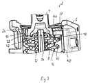
- the drawing shows part of an actuator for a braking device 2 with a plunger 4, which is axially displaceable in a housing 6 and by one Brake pedal can be actuated via a mechanical connection (not shown), with a spacer ring 8, which is inside a guide ring 10 is axially displaceable, which is in positive connection with the plunger, and with one from the plunger over the spacer ring 8 and one Gradation spring 12 axially movable piston 14.
- the gradation spring 12 is supported on the piston 14 and on the spacer ring 8 from.
- Reference numeral 15 denotes an outer return spring, which are on the guide ring 10 and a housing Support stop (not shown).
- Reference number 16 denotes a feeling spring that is on the one hand on the spacer ring 8 and on the other hand on a housing-fixed stop (not shown) supports.
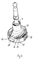
- the plunger 4 has an elongated base plate on the piston side 18 on that in a complementary fashion Recording 20 of the guide ring 10 is inserted.
- a plurality of spaced elongated holes 22 are formed, which extend in the axial direction.
- the spacer ring 8 has several angled in the drawing upward-pointing bends 24, the elongated holes 22 are assigned, protrude into this and the leadership serve the spacer ring in the guide ring.
- the base plate 18 has a central oval plate part 26 on, in the direction of the main oval axis two mutually opposed rectangular protruding arms 28, 30, which in groove-like recesses 32, 34th of the guide ring 10 are arranged and the guide ring 10 protrude in the radial direction.
- the inner contour 36 of the Guide ring 10 corresponds to the outer contour 37 of the middle oval plate part 26 of the base plate 18th
- the inner contour 36 of the guide ring 10 and thus the Outer contour 37 of the base plate 18 of the plunger 4 can except oval also circular, non-round or polygonal his.
- the guide ring 10 points transversely to the main axis of the oval the inner contour 36, in the drawing in the direction of the minor axis of the oval, a radially aligned rectangular Window 38, which projects radially outwards, and preferably, as shown, with an upper frame part and side frame parts.
- the actuator 38 projects into one Guide slot 40 of the housing 6 into it.
- the guide slot 40 serves to receive and guide a displacement sensor slide (not shown), the end of which from the window 38 is recorded and thus the movement of the plunger 4th follows.
- the elongated holes 22 of the guide ring 10 are located diagonally in the angular ranges between the major and minor axes of the oval of the inner contour 36, in the present case between the window 38 and the groove-like recesses 32, 34 and the diagonally opposite areas of the guide ring 10th
- the inner contour 36 of the guide ring 10 faces in the area of the elongated holes 22 on the spacer ring 8 facing Underside step recesses 42.1, 42.2, 42.3, 42.4 that extend to the elongated holes and their Length is equal to the length of the elongated holes.
- circle segments 44.1, 44.2, 44.3, and 44.4 stand, in the area of the groove-shaped recesses 32, 34, of the window 38 and diagonally opposite the window.
- the return spring 15 lies on these circular segments on.
- the spacer ring 8 lies within the circle segments 44 and has side arms 21, each end with the already mentioned bend 24 are provided. The poor 21 protrude into the stepped recesses 42 and the bends 24 into the elongated holes 22 of the guide ring 10.
- the plunger 4 and the spacer ring 8th on the one hand it is ensured that the guide ring Tappet on the outside opposite the housing 6 and the spacer ring 8 with its arms 21 and bends 24 in the elongated holes 22 leads.
- the window 34 secures the tappet 4 against Twisting and thereby ensures trouble-free articulation of the displacement sensor slide on the tappet.
Landscapes
- Engineering & Computer Science (AREA)
- Transportation (AREA)
- Mechanical Engineering (AREA)
- Braking Systems And Boosters (AREA)
- Braking Elements And Transmission Devices (AREA)
- Braking Arrangements (AREA)
- Valves And Accessory Devices For Braking Systems (AREA)
Abstract
Description
- Fig. 1
- einen ersten Schnitt durch einen Teil einer erfindungsgemäßen Betätigungsvorrichtung für ein Bremsgerät,
- Fig. 2
- einen zweiten Schnitt durch das Teil nach Fig. 1,
- Fig. 3
- einen gedrehten Schnitt (3D-Ansicht) des Teils nach den Fig. 1 und 2,
- Fig. 4
- einen bei der erfindungsgemäßen Betätigungsvor- richtung vorgesehenen Stößel mit Führungsring in perspektivischer Draufsicht,
- Fig. 5
- den Stößel mit Führungsring nach Fig. 4 in perspektivischer Unteransicht,
- Fig. 6
- eine perspektivische Draufsicht auf den bei der Betätigungsvorrichtung verwendeten erfindungsgemäßen Führungsring und
- Fig. 7
- den Führungsring nach Fig. 4 in einer perspektivischen Unteransicht.
Claims (10)
- Betätigungsvorrichtung für ein Bremsgerät mitgekennzeichnet durch folgende Merkmale:einem Stößel, der axial verschiebbar in einem Gehäuse des Bremsgerätes angeordnet ist und mechanisch mit einem Bremspedal verbunden ist,einem vom Stößel betätigbaren Kolben zur Ansteuerung eines Bremsventils,einem einen geringen Leerhub realisierenden, vom Stößel beaufschlagbaren Bauteil undeinem mit dem Stößel und durch den Stößel bewegbaren Wegsensor-Schieber zur Erfassung der Axialbewegung des Stößels,der Stößel (4) weist an seinem dem Kolben (14) zugewandten Ende eine Grundplatte (18) auf,die Grundplatte (18) ist drehfest in einer Aufnahme (20) eines Führungsringes (10) angeordnet,der Führungsring (10) ist drehfest im Gehäuse (6) geführt,der Führungsring (10) weist beabstandete, in axialer Richtung verlaufende Langlöcher (22) auf,das den Leerhub realisierende Bauteil ist ein Distanzring (8), welcher im Führungsring (10) angeordnet und geführt ist,der Distanzring (8) weist zur Führung im Führungsring an seinem Außenumfang den Langlöchern (22) des Führungsringes (10) zugeordnete und in die Langlöcher ragende Abwinklungen (24) auf,der Führungsring (10) weist ein radial nach außen vorstehendes Fenster (38) auf zur Aufnahme des Wegsensor-Schiebers unddas Fenster (38) des Führungsringes (10) ragt in einen im Gehäuse (6) ausgebildeten Führungsschlitz (40) für den Wegsensor-Schieber hinein, dessen Ende vom Fenster aufgenommen ist und der der Stößelbewegung folgt.
- Betätigungsvorrichtung nach Anspruch 1, dadurch gekennzeichnet, dass die Grundplatte (18) eine komplementär zur Innenkontur (36) der Aufnahme (20) des Führungsringes (10) ausgebildete Außenkontur (37) aufweist.
- Betätigungsvorrichtung nach Anspruch 1 oder, dadurch gekennzeichnet, dass die Außenkontur (37) der Grundplatte (18) und entsprechend die Innenkontur (36) des Führungsringes (10) oval, kreisförmig, unrund oder mehreckig ausgebildet ist.
- Betätigungsvorrichtung nach Anspruch 3, dadurch gekennzeichnet, dass die Grundplatte (18) zwei diametral gegenüber angeordnete, radial wegstrebende Arme (28, 30) aufweist, die in nutartige Ausnehmungen (32, 34) des Führungsringes (10) eingreifen.
- Betätigungsvorrichtung nach Anspruch 4, dadurch gekennzeichnet, dass die Arme (28, 30) den Führungsring (10) in radialer Richtung nach außen überragen.
- Betätigungsvorrichtung nach Anspruch 5, dadurch gekennzeichnet, dass im Gehäuse (6) Anschläge (48, 50) für die Arme (28, 30) der Grundplatte (18) des Stößels (4) vorgesehen sind.
- Betätigungsvorrichtung nach einem der vorhergehenden Ansprüche, dadurch gekennzeichnet, dass der Führungsring (10) im Bereich der Langlöcher (22) auf der dem Distanzring (8) zugewandten Unterseite stufige Ausnehmungen (42.1, 42.2, 42.3, 42.4) aufweist, die sich bis zu den Langlöchern (22) erstrecken und zwischen denen kreissegmentförmige Vorsprünge (44.1, 44.2, 44.3, 44.4) verbleiben.
- Betätigungsvorrichtung nach Anspruch 7, dadurch gekennzeichnet, dass der Distanzring (8) im Führungsring (10) innerhalb der kreissegmentförmigen Vorsprünge (44) angeordnet ist.
- Betätigungsvorrichtung nach Anspruch 8, dadurch gekennzeichnet, dass der Distanzring (8) an seinem Außenumfang seitliche Arme (21) aufweist, die jeweils am Ende mit einer Abwinklung (24) versehen sind, wobei die Arme (21) in die stufigen Ausnehmungen (42) und die Abwinklungen (24) in die Langlöcher (22) des Führungsringes (10) hineinragen.
- Betätigungsvorrichtung nach einem der vorhergehenden Ansprüche, dadurch gekennzeichnet, dass der Führungsring (10) aus Kunststoff besteht.
Applications Claiming Priority (2)
| Application Number | Priority Date | Filing Date | Title |
|---|---|---|---|
| DE10224805A DE10224805A1 (de) | 2002-06-05 | 2002-06-05 | Betätigungsvorrichtung für ein Bremsgerät |
| DE10224805 | 2002-06-05 |
Publications (2)
| Publication Number | Publication Date |
|---|---|
| EP1369329A1 true EP1369329A1 (de) | 2003-12-10 |
| EP1369329B1 EP1369329B1 (de) | 2005-02-09 |
Family
ID=29432633
Family Applications (1)
| Application Number | Title | Priority Date | Filing Date |
|---|---|---|---|
| EP03009453A Expired - Lifetime EP1369329B1 (de) | 2002-06-05 | 2003-04-25 | Betätigungsvorrichtung für ein Bremsgerät |
Country Status (3)
| Country | Link |
|---|---|
| US (1) | US6953228B2 (de) |
| EP (1) | EP1369329B1 (de) |
| DE (2) | DE10224805A1 (de) |
Cited By (2)
| Publication number | Priority date | Publication date | Assignee | Title |
|---|---|---|---|---|
| US6953228B2 (en) * | 2002-06-05 | 2005-10-11 | Wabco Gmbh & Co. Ohg | Actuating device for a brake unit of an electronically controlled vehicle brake system |
| WO2008107023A1 (de) * | 2007-03-05 | 2008-09-12 | Continental Teves Ag & Co. Ohg | Betätigungseinheit für eine kraftfahrzeugbremsanlage |
Families Citing this family (4)
| Publication number | Priority date | Publication date | Assignee | Title |
|---|---|---|---|---|
| US8783791B2 (en) | 2012-05-30 | 2014-07-22 | Bendix Commercial Vehicle Systems Llc | Dual circuit pneumatic foot valve with electronically controlled proportional modulator (ECPM) and operator input sensing |
| US10131336B2 (en) | 2016-09-26 | 2018-11-20 | Bendix Commercial Vehicle Systems Llc | System and method for braking a vehicle |
| DE102018127907A1 (de) * | 2018-11-08 | 2020-05-14 | Wabco Gmbh | Fußbremsventil einer Druckluftbremsanlage |
| DE102021112831A1 (de) * | 2021-05-18 | 2022-11-24 | Zf Cv Systems Global Gmbh | Elektropneumatische Baueinheit mit integrierter Ausfallsicherheitsventilanordnung für Mehrfachfehler, elektronisch steuerbares pneumatisches Bremssystem, sowie Verfahren zum Betreiben eines Bremssystems |
Citations (7)
| Publication number | Priority date | Publication date | Assignee | Title |
|---|---|---|---|---|
| DE3841749A1 (de) * | 1988-12-12 | 1990-06-13 | Wabco Westinghouse Fahrzeug | Verfahren und anordnung eines elektrisch gesteuerten bremskreises einer mehrkreis-bremsanlage mit druckmittelbetaetigten bremsen |
| DE4232492A1 (de) * | 1992-09-28 | 1994-03-31 | Grau Gmbh | Betriebsbremsventil für eine elektrisch oder pneumatisch betätigbare Bremsanlage eines Kraftfahrzeugs |
| DE4417184A1 (de) * | 1994-05-17 | 1995-11-23 | Wabco Gmbh | Betätigungseinrichtung für ein Ventil |
| DE19653264A1 (de) * | 1996-12-20 | 1998-06-25 | Bosch Gmbh Robert | Elektronisch steuerbares Bremssystem für Fahrzeuge, insbesondere Nutzfahrzeuge |
| DE19701069A1 (de) * | 1997-01-15 | 1998-07-16 | Bosch Gmbh Robert | Vorrichtung zur Messung des Bremspedalwegs |
| DE19835574A1 (de) * | 1998-08-06 | 2000-02-10 | Mannesmann Sachs Ag | Betätigungseinrichtung für pneumatische Kupplungsbetätigung mit Überlast- oder/und Fehlbedienungsschutz |
| EP1042148A1 (de) * | 1997-12-22 | 2000-10-11 | Bosch Systemes de Freinage | Hauptzylinder für elektrohydraulische kraftfahrzeugbremsanlage |
Family Cites Families (30)
| Publication number | Priority date | Publication date | Assignee | Title |
|---|---|---|---|---|
| DE1151745B (de) | 1955-10-10 | 1963-07-18 | Westinghouse Bremsen Gmbh | Bremsventil fuer Zweikreis-Druckluft-bremsanlagen in Kraftwagen |
| DE1116084B (de) | 1958-04-12 | 1961-10-26 | Knorr Bremse Gmbh | Elektromagnetisch betaetigtes Steuerventil fuer Druckluftbremsanlagen an Anhaengerfahrzeugen |
| US3937527A (en) * | 1974-04-22 | 1976-02-10 | Knorr-Bremse Gmbh | Fluid pressure relay valve |
| DE2425449C2 (de) | 1974-05-25 | 1982-11-25 | Knorr-Bremse GmbH, 8000 München | Relaisventil für eine druckmittelbetätigte und blockiergeschützte Fahrzeugbremsanlage |
| DE2642041A1 (de) * | 1976-09-18 | 1978-03-23 | Wabco Westinghouse Gmbh | Betaetigungseinrichtung fuer druckmittel-bremsanlagen |
| DE2937657A1 (de) * | 1979-09-18 | 1981-04-02 | Wabco Fahrzeugbremsen Gmbh, 3000 Hannover | Motorwagen-bremsventil mit elektrischer steuereinrichtung |
| DE3120203A1 (de) | 1981-05-21 | 1982-12-23 | Wabco Westinghouse Fahrzeugbremsen GmbH, 3000 Hannover | Relaisventil |
| US4480663A (en) * | 1982-09-13 | 1984-11-06 | Wabco Fahrzeugbremsen Gmbh | Pneumatic relay valve |
| JPS59118557A (ja) * | 1982-12-23 | 1984-07-09 | Mazda Motor Corp | 自動車の電磁サ−ボブレ−キ装置 |
| DE3504096A1 (de) * | 1985-02-07 | 1986-08-07 | Wabco Westinghouse Fahrzeugbremsen GmbH, 3000 Hannover | Sollwertgeber |
| DE3611941A1 (de) * | 1986-04-09 | 1987-10-22 | Wabco Westinghouse Fahrzeug | Bremswertgeber |
| IT208269Z2 (it) * | 1986-10-27 | 1988-04-29 | Magneti Marelli Spa | Distributore di tipo duplex per un impianto pneumatico di frenatura per autoveicolo provvisto di rallentatore ausiliario |
| DE3715148A1 (de) | 1987-05-07 | 1988-11-24 | Wabco Westinghouse Fahrzeug | Druckregelventil |
| DE3924327A1 (de) * | 1989-04-29 | 1990-10-31 | Teves Gmbh Alfred | Wegsensor zur messung mechanischer bewegungsgroessen |
| DE4016756A1 (de) | 1990-05-25 | 1991-11-28 | Teves Gmbh Alfred | Bremsdruckregelvorrichtung |
| DE4236045A1 (de) | 1992-04-03 | 1993-11-04 | Teves Gmbh Alfred | Hydraulisches umschaltventil fuer eine fahrzeugbremsanlage |
| GB9215510D0 (en) * | 1992-07-22 | 1992-09-02 | Grau Ltd | Braking systems |
| US5365791A (en) * | 1992-11-10 | 1994-11-22 | Allied-Signal Inc. | Signal generator |
| DE4343386B4 (de) * | 1993-12-18 | 2004-04-22 | Robert Bosch Gmbh | Hydraulische Bremsanlage für Straßenfahrzeuge, insbesondere Personenkraftwagen |
| EP0782518A1 (de) * | 1995-02-22 | 1997-07-09 | Bosch Braking Systems Corporation | Hydraulisch und elektrisch betriebene feststellbremsanlage |
| US5831232A (en) * | 1996-11-12 | 1998-11-03 | Westinghouse Air Brake Company | Pneumatic emergency brake application valve and an associated electrical signaling switch |
| JP3771672B2 (ja) * | 1997-05-27 | 2006-04-26 | 曙ブレーキ工業株式会社 | ブレーキペダル操作検出装置 |
| DE19736646C2 (de) * | 1997-08-22 | 1999-06-24 | Lucas Ind Plc | Vollhydraulische Bremskrafterzeuger/Hauptzylinder-Einheit mit verbesserter Bremsdruckrückmeldung |
| DE19756000A1 (de) * | 1997-12-17 | 1999-06-24 | Wabco Gmbh | Anordnung mit einer Ventileinrichtung |
| DE19806936A1 (de) * | 1998-02-19 | 1999-08-26 | Wabco Gmbh | Anordnung mit einer Ventileinrichtung |
| EP1127228A4 (de) * | 1999-09-07 | 2006-04-26 | Akebono Corp North America | Automatisch nachstellbare handbremsbetätigungsvorrichtung sowie gehäuse aus leichtem material |
| US6612659B2 (en) * | 2001-08-28 | 2003-09-02 | Delphi Technologies, Inc. | Intelligent input push rod assembly |
| DE10224806A1 (de) * | 2002-06-05 | 2004-01-08 | Wabco Gmbh & Co. Ohg | Betätigungsvorrichtung für ein Bremsgerät |
| DE10224804A1 (de) * | 2002-06-05 | 2004-01-08 | Wabco Gmbh & Co. Ohg | Ventil |
| DE10224805A1 (de) * | 2002-06-05 | 2004-03-25 | Wabco Gmbh & Co. Ohg | Betätigungsvorrichtung für ein Bremsgerät |
-
2002
- 2002-06-05 DE DE10224805A patent/DE10224805A1/de not_active Withdrawn
-
2003
- 2003-04-25 DE DE50300301T patent/DE50300301D1/de not_active Expired - Lifetime
- 2003-04-25 EP EP03009453A patent/EP1369329B1/de not_active Expired - Lifetime
- 2003-06-03 US US10/453,838 patent/US6953228B2/en not_active Expired - Fee Related
Patent Citations (7)
| Publication number | Priority date | Publication date | Assignee | Title |
|---|---|---|---|---|
| DE3841749A1 (de) * | 1988-12-12 | 1990-06-13 | Wabco Westinghouse Fahrzeug | Verfahren und anordnung eines elektrisch gesteuerten bremskreises einer mehrkreis-bremsanlage mit druckmittelbetaetigten bremsen |
| DE4232492A1 (de) * | 1992-09-28 | 1994-03-31 | Grau Gmbh | Betriebsbremsventil für eine elektrisch oder pneumatisch betätigbare Bremsanlage eines Kraftfahrzeugs |
| DE4417184A1 (de) * | 1994-05-17 | 1995-11-23 | Wabco Gmbh | Betätigungseinrichtung für ein Ventil |
| DE19653264A1 (de) * | 1996-12-20 | 1998-06-25 | Bosch Gmbh Robert | Elektronisch steuerbares Bremssystem für Fahrzeuge, insbesondere Nutzfahrzeuge |
| DE19701069A1 (de) * | 1997-01-15 | 1998-07-16 | Bosch Gmbh Robert | Vorrichtung zur Messung des Bremspedalwegs |
| EP1042148A1 (de) * | 1997-12-22 | 2000-10-11 | Bosch Systemes de Freinage | Hauptzylinder für elektrohydraulische kraftfahrzeugbremsanlage |
| DE19835574A1 (de) * | 1998-08-06 | 2000-02-10 | Mannesmann Sachs Ag | Betätigungseinrichtung für pneumatische Kupplungsbetätigung mit Überlast- oder/und Fehlbedienungsschutz |
Cited By (3)
| Publication number | Priority date | Publication date | Assignee | Title |
|---|---|---|---|---|
| US6953228B2 (en) * | 2002-06-05 | 2005-10-11 | Wabco Gmbh & Co. Ohg | Actuating device for a brake unit of an electronically controlled vehicle brake system |
| WO2008107023A1 (de) * | 2007-03-05 | 2008-09-12 | Continental Teves Ag & Co. Ohg | Betätigungseinheit für eine kraftfahrzeugbremsanlage |
| US8500222B2 (en) | 2007-03-05 | 2013-08-06 | Continental Teves Ag & Co. Ohg | Actuating unit for a motor vehicle brake system |
Also Published As
| Publication number | Publication date |
|---|---|
| DE10224805A1 (de) | 2004-03-25 |
| US20040026182A1 (en) | 2004-02-12 |
| DE50300301D1 (de) | 2005-03-17 |
| EP1369329B1 (de) | 2005-02-09 |
| US6953228B2 (en) | 2005-10-11 |
Similar Documents
| Publication | Publication Date | Title |
|---|---|---|
| EP0223921B1 (de) | Parksperre für automatische Getriebe von Kraftfahrzeugen | |
| DE10159461B4 (de) | Vorrichtung zur Halterung von Behältern, insbesondere von Getränkebehältern | |
| EP1725437B1 (de) | Vorrichtung zum sperren der lenkspindel eines kraftfahrzeugs | |
| DE4203680C1 (de) | ||
| DE10258285A1 (de) | Fahrpedalmodul | |
| DE60221895T2 (de) | Federelement für rotierende bewegung | |
| WO2016177706A1 (de) | Möbelscharnier mit einem dämpfer und einer feder | |
| DE102006054753A1 (de) | Elektromechanische Antriebsvorrichtung zum Einsatz in einer Heckklappe eines Kraftfahrzeugs | |
| DE19744199C2 (de) | Gleitelement | |
| DE102008018140A1 (de) | Fahrpedal | |
| DE2630360C3 (de) | Zentreifuge zum Trennen von Probenflüssigkeiten in röhrchenförmigen Behältern | |
| EP1369329B1 (de) | Betätigungsvorrichtung für ein Bremsgerät | |
| DE3247421A1 (de) | Antriebsvorrichtung, insbesondere fuer scheibenwischer von kraftfahrzeugen | |
| DE3610868A1 (de) | Drehverschluss zur verbindung plattenfoermiger bauteile | |
| EP1711691A1 (de) | Verbindungsvorrichtung f r einen bet tigungshebel und e in abst tzelement einer ventilsteuerung einer brennkraftmasc hine | |
| EP0175156A2 (de) | Elektrischer Schalter | |
| DE2819496B2 (de) | Vorrichtung zum Anbringen einer Dichtung am Rand einer Scheibe | |
| DE4204630C2 (de) | Kugelraste für die Lagefixierung eines beweglichen Stellelementes | |
| WO2020177805A1 (de) | Drehmomentwerkzeug | |
| DE69313577T2 (de) | Verbesserung an Türgriffen mit einer plattenförmigen Handhabe | |
| DE112008000928T5 (de) | Verfahren zur Montage eines Kältemaschinenkompressors | |
| DE4228493C1 (de) | Kurbeltrieb für einen Scheibenwischerantrieb eines Kraftfahrzeugs | |
| EP1369328B1 (de) | Betätigungsvorrichtung für ein Bremsgerät | |
| DE102004034833A1 (de) | Markiereinheit des Typs Nummerierer zum Markieren durch Umformung | |
| DE3325531C2 (de) |
Legal Events
| Date | Code | Title | Description |
|---|---|---|---|
| PUAI | Public reference made under article 153(3) epc to a published international application that has entered the european phase |
Free format text: ORIGINAL CODE: 0009012 |
|
| AK | Designated contracting states |
Kind code of ref document: A1 Designated state(s): AT BE BG CH CY CZ DE DK EE ES FI FR GB GR HU IE IT LI LU MC NL PT RO SE SI SK TR |
|
| AX | Request for extension of the european patent |
Extension state: AL LT LV MK |
|
| GRAP | Despatch of communication of intention to grant a patent |
Free format text: ORIGINAL CODE: EPIDOSNIGR1 |
|
| 17P | Request for examination filed |
Effective date: 20040611 |
|
| AKX | Designation fees paid |
Designated state(s): DE FR IT SE |
|
| GRAS | Grant fee paid |
Free format text: ORIGINAL CODE: EPIDOSNIGR3 |
|
| GRAA | (expected) grant |
Free format text: ORIGINAL CODE: 0009210 |
|
| AK | Designated contracting states |
Kind code of ref document: B1 Designated state(s): DE FR IT SE |
|
| REG | Reference to a national code |
Ref country code: IE Ref legal event code: FG4D Free format text: GERMAN |
|
| REG | Reference to a national code |
Ref country code: SE Ref legal event code: TRGR |
|
| REF | Corresponds to: |
Ref document number: 50300301 Country of ref document: DE Date of ref document: 20050317 Kind code of ref document: P |
|
| PLBE | No opposition filed within time limit |
Free format text: ORIGINAL CODE: 0009261 |
|
| STAA | Information on the status of an ep patent application or granted ep patent |
Free format text: STATUS: NO OPPOSITION FILED WITHIN TIME LIMIT |
|
| ET | Fr: translation filed | ||
| 26N | No opposition filed |
Effective date: 20051110 |
|
| REG | Reference to a national code |
Ref country code: DE Ref legal event code: R081 Ref document number: 50300301 Country of ref document: DE Owner name: WABCO EUROPE BVBA, BE Free format text: FORMER OWNER: WABCO GMBH, 30453 HANNOVER, DE Effective date: 20121214 |
|
| PGFP | Annual fee paid to national office [announced via postgrant information from national office to epo] |
Ref country code: FR Payment date: 20140425 Year of fee payment: 12 Ref country code: SE Payment date: 20140415 Year of fee payment: 12 |
|
| REG | Reference to a national code |
Ref country code: SE Ref legal event code: EUG |
|
| REG | Reference to a national code |
Ref country code: FR Ref legal event code: ST Effective date: 20151231 |
|
| PG25 | Lapsed in a contracting state [announced via postgrant information from national office to epo] |
Ref country code: FR Free format text: LAPSE BECAUSE OF NON-PAYMENT OF DUE FEES Effective date: 20150430 Ref country code: SE Free format text: LAPSE BECAUSE OF NON-PAYMENT OF DUE FEES Effective date: 20150426 |
|
| PGFP | Annual fee paid to national office [announced via postgrant information from national office to epo] |
Ref country code: IT Payment date: 20220429 Year of fee payment: 20 Ref country code: DE Payment date: 20220430 Year of fee payment: 20 |
|
| REG | Reference to a national code |
Ref country code: DE Ref legal event code: R071 Ref document number: 50300301 Country of ref document: DE |
|
| REG | Reference to a national code |
Ref country code: DE Ref legal event code: R081 Ref document number: 50300301 Country of ref document: DE Owner name: ZF CV SYSTEMS EUROPE BV, BE Free format text: FORMER OWNER: WABCO EUROPE BVBA, BRUXELLES, BE |