EP1369266A1 - Kupplungsvorrichtung - Google Patents
Kupplungsvorrichtung Download PDFInfo
- Publication number
- EP1369266A1 EP1369266A1 EP03450094A EP03450094A EP1369266A1 EP 1369266 A1 EP1369266 A1 EP 1369266A1 EP 03450094 A EP03450094 A EP 03450094A EP 03450094 A EP03450094 A EP 03450094A EP 1369266 A1 EP1369266 A1 EP 1369266A1
- Authority
- EP
- European Patent Office
- Prior art keywords
- coupling
- ball
- socket
- sealing ring
- trailer
- Prior art date
- Legal status (The legal status is an assumption and is not a legal conclusion. Google has not performed a legal analysis and makes no representation as to the accuracy of the status listed.)
- Granted
Links
Images

Classifications
-
- B—PERFORMING OPERATIONS; TRANSPORTING
- B60—VEHICLES IN GENERAL
- B60D—VEHICLE CONNECTIONS
- B60D1/00—Traction couplings; Hitches; Draw-gear; Towing devices
- B60D1/58—Auxiliary devices
- B60D1/586—Lubrication means
-
- B—PERFORMING OPERATIONS; TRANSPORTING
- B60—VEHICLES IN GENERAL
- B60D—VEHICLE CONNECTIONS
- B60D1/00—Traction couplings; Hitches; Draw-gear; Towing devices
- B60D1/01—Traction couplings or hitches characterised by their type
- B60D1/06—Ball-and-socket hitches
- B60D1/065—Ball-and-socket hitches characterised by the hitch mechanism
-
- B—PERFORMING OPERATIONS; TRANSPORTING
- B60—VEHICLES IN GENERAL
- B60D—VEHICLE CONNECTIONS
- B60D1/00—Traction couplings; Hitches; Draw-gear; Towing devices
- B60D1/58—Auxiliary devices
- B60D1/60—Covers, caps or guards, e.g. comprising anti-theft devices
Definitions
- the invention relates to a coupling device between a towing vehicle and a trailer with one on a clutch carrier the traction vehicle arranged coupling ball and a coupling ball from the top, trailer-side ball socket (AT 406 849 B).
- Coupling devices with a coupling ball allow comparatively high pivoting movements between towing vehicle and trailer, but are subject especially in dusty environment, as for example od tractors on fields od.
- increased wear because as a result of the pivoting movements between coupling ball and ball socket always acting as an abrasive mineral dust, for example enters the area between coupling ball and ball socket and there causes a material abrasion.
- the invention is therefore based on the object, a ball coupling to create the kind described, which ball coupling through an increase in the service life with simple means and a reduction of the Weares distinguished.
- the invention solves this problem in that between the pan rim the ball socket and the coupling carrier of the coupling ball an elastic deformable sealing ring is arranged, on the one hand at the edge of the pan and on the other hand, on the clutch carrier biased.
- This elastically deformable sealing ring shields the sliding surfaces of Ball socket and coupling ball with simple means safe from the environment from, so that no accelerating or causing a wear Od materials such as mineral dust. Like. In the area between coupling ball and ball socket can get. At the same time the sealing ring prevents a Leakage of lubricant from the coupling device, the good Mobility of the coupling device is not limited and the Off-road capability of towing vehicle-trailer combination in full preserved. With the invention, the life of a coupling device from coupling ball and ball socket with simple means essential elevated.
- the sealing ring is elastic is deformable and bears under pretension on the coupling carrier, so that even at maximum pivoting movements between coupling ball and ball socket always a secure seal of the sliding surfaces to the environment is guaranteed.
- the material for the sealing ring make sure that the material itself contributes to no wear on the sliding surfaces.
- a material is chosen which even itself as Lubricant for the coupling device acts.
- the inner diameter of the sealing ring is smaller than that Diameter of the coupling ball is. In this case, it is ensured that the Sealing ring in the transition region between the socket edge of the ball socket and abuts the coupling carrier on the sliding surface of the coupling ball and no wear-promoting material can penetrate into this area. It goes without saying that the sealing ring to the coupling device may have adapted form, or he is due to its deformability adapts itself to the shape of the coupling device.
- the coupling ball inside the ball socket with the help of one of the coupling ball associated hold-down is lockable, which is the ball socket and the sealing ring comprises outside. This ensures that the sliding surfaces of coupling ball and ball socket hermetic to the environment are sealed.
- a conventional ball socket be assigned, in which the hold-down of the ball socket and on the Coupling ball acts.
- a coupling device 1 according to the invention between a not illustrated towing vehicle and also not shown Trailer comprises a arranged on a coupling carrier 2 coupling ball 3 and a coupling ball 3 from above comprehensive ball socket. 4
- the trailer is articulated via an integrally formed on the ball socket 4 stem part 5.
- an elastically deformable Sealing ring 8 is arranged.
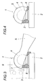
- the sealing ring 8 is under prestress on the one hand on the pan edge 7 and on the other hand on the coupling carrier. 2 on, so that the sliding surfaces 6 even at maximum deflection between coupling ball 3 and ball socket 4 from one shown in Figs. 1 and 2 neutral middle layer, always hermetically sealed against the environment and penetration of wear-promoting materials by simple means is prevented.
Landscapes
- Engineering & Computer Science (AREA)
- Transportation (AREA)
- Mechanical Engineering (AREA)
- Sealing Devices (AREA)
- Pivots And Pivotal Connections (AREA)
- Mechanical Operated Clutches (AREA)
- Hydraulic Clutches, Magnetic Clutches, Fluid Clutches, And Fluid Joints (AREA)
- Control Of Motors That Do Not Use Commutators (AREA)
- Seal Device For Vehicle (AREA)
- Physical Deposition Of Substances That Are Components Of Semiconductor Devices (AREA)
- Arrangement And Mounting Of Devices That Control Transmission Of Motive Force (AREA)
Abstract
Description
- Fig. 1
- eine Kugelkupplung in teilweise geschnittener Seitenansicht,
- Fig. 2
- die Kugelkupplung aus Fig. 1 in Vorderansicht,
- Fig. 3 und 4
- die Kugelkupplung aus Fig. 1 mit gegenüber der Kupplungskugel verschwenkter Kugelpfanne um eine Quer- und um eine Längsachse.
Claims (3)
- Kupplungsvorrichtung (1) zwischen einem Zugfahrzeug und einem Anhänger mit einer auf einem Kupplungsträger (2) des Zugfahrzeuges angeordneten Kupplungskugel (3) und einer die Kupplungskugel (3) von oben umfassenden, anhängerseitigen Kugelpfanne (4), dadurch gekennzeichnet, daß zwischen dem Pfannenrand (7) der Kugelpfanne (4) und dem Kupplungsträger (2) der Kupplungskugel (3) ein elastisch verformbarer Dichtungsring (8) angeordnet ist, der einerseits am Pfannenrand (7) und anderseits am Kupplungsträger (2) unter Vorspannung anliegt.
- Kupplungsvorrichtung nach Anspruch 1, dadurch gekennzeichnet, daß der Innendurchmesser des Dichtungsringes (8) kleiner als der Durchmesser der Kupplungskugel (3) ist.
- Kupplungsvorrichtung nach Anspruch 1 oder 2, dadurch gekennzeichnet, daß ein am Kupplungsträger (2) gelagerter Niederhalter (9) für die Kugelpfanne (4) vorgesehen ist, der den Dichtungsring (8) außen umfaßt.
Priority Applications (1)
| Application Number | Priority Date | Filing Date | Title |
|---|---|---|---|
| AT03450094T ATE340710T1 (de) | 2002-06-03 | 2003-04-17 | Kupplungsvorrichtung |
Applications Claiming Priority (2)
| Application Number | Priority Date | Filing Date | Title |
|---|---|---|---|
| AT0084102A AT412459B (de) | 2002-06-03 | 2002-06-03 | Kupplungsvorrichtung |
| AT8412002 | 2002-06-03 |
Publications (2)
| Publication Number | Publication Date |
|---|---|
| EP1369266A1 true EP1369266A1 (de) | 2003-12-10 |
| EP1369266B1 EP1369266B1 (de) | 2006-09-27 |
Family
ID=29425364
Family Applications (1)
| Application Number | Title | Priority Date | Filing Date |
|---|---|---|---|
| EP03450094A Expired - Lifetime EP1369266B1 (de) | 2002-06-03 | 2003-04-17 | Kupplungsvorrichtung |
Country Status (3)
| Country | Link |
|---|---|
| EP (1) | EP1369266B1 (de) |
| AT (2) | AT412459B (de) |
| DE (1) | DE50305153D1 (de) |
Cited By (4)
| Publication number | Priority date | Publication date | Assignee | Title |
|---|---|---|---|---|
| WO2006122807A1 (de) * | 2005-05-18 | 2006-11-23 | Jost-Werke Gmbh & Co. Kg | Kugelkupplung mit abgedichtetem anlagebereich |
| WO2008122350A1 (de) * | 2007-04-10 | 2008-10-16 | Jost-Werke Gmbh | Kugelkupplung mit relativbeweglich aufgenommener dichtung |
| EP2682290A1 (de) * | 2012-07-04 | 2014-01-08 | RockingerAgriculture GmbH | Kupplungspfanne mit Festkörperschmierstoff |
| EP4628330A1 (de) | 2024-04-03 | 2025-10-08 | Walterscheid GmbH | Kupplungsanordnung |
Citations (6)
| Publication number | Priority date | Publication date | Assignee | Title |
|---|---|---|---|---|
| GB300750A (en) * | 1927-10-03 | 1928-11-22 | Thornycroft John I & Co Ltd | Improvements in or relating to coupling devices for road vehicles |
| US2308613A (en) * | 1941-06-20 | 1943-01-19 | Letourneau Inc | Ball and socket unit |
| DE929107C (de) * | 1954-07-17 | 1955-06-20 | Scharfenbergkupplung Ag | Anhaengerkupplung fuer Kraftfahrzeuge |
| GB2251838A (en) * | 1991-01-16 | 1992-07-22 | Arthur Goddard | Vehicle coupling assembly |
| DE4314810A1 (de) * | 1992-07-23 | 1994-01-27 | Lorinser Sport Service | Vorrichtung zur Anbringung von Bild- bzw. Schrifttafeln an Lastkraftwagen u. dgl. |
| AT406849B (de) | 1999-04-30 | 2000-09-25 | Scharmueller Josef Ing | Kupplungsvorrichtung zwischen einem zugfahrzeug, insbesondere einem ackerschlepper, und einem anhänger |
-
2002
- 2002-06-03 AT AT0084102A patent/AT412459B/de not_active IP Right Cessation
-
2003
- 2003-04-17 AT AT03450094T patent/ATE340710T1/de not_active IP Right Cessation
- 2003-04-17 EP EP03450094A patent/EP1369266B1/de not_active Expired - Lifetime
- 2003-04-17 DE DE50305153T patent/DE50305153D1/de not_active Expired - Lifetime
Patent Citations (6)
| Publication number | Priority date | Publication date | Assignee | Title |
|---|---|---|---|---|
| GB300750A (en) * | 1927-10-03 | 1928-11-22 | Thornycroft John I & Co Ltd | Improvements in or relating to coupling devices for road vehicles |
| US2308613A (en) * | 1941-06-20 | 1943-01-19 | Letourneau Inc | Ball and socket unit |
| DE929107C (de) * | 1954-07-17 | 1955-06-20 | Scharfenbergkupplung Ag | Anhaengerkupplung fuer Kraftfahrzeuge |
| GB2251838A (en) * | 1991-01-16 | 1992-07-22 | Arthur Goddard | Vehicle coupling assembly |
| DE4314810A1 (de) * | 1992-07-23 | 1994-01-27 | Lorinser Sport Service | Vorrichtung zur Anbringung von Bild- bzw. Schrifttafeln an Lastkraftwagen u. dgl. |
| AT406849B (de) | 1999-04-30 | 2000-09-25 | Scharmueller Josef Ing | Kupplungsvorrichtung zwischen einem zugfahrzeug, insbesondere einem ackerschlepper, und einem anhänger |
Cited By (5)
| Publication number | Priority date | Publication date | Assignee | Title |
|---|---|---|---|---|
| WO2006122807A1 (de) * | 2005-05-18 | 2006-11-23 | Jost-Werke Gmbh & Co. Kg | Kugelkupplung mit abgedichtetem anlagebereich |
| AU2006249072B2 (en) * | 2005-05-18 | 2011-08-18 | Jost-Werke Gmbh | Ball-shaped coupling comprising a sealed contact area |
| WO2008122350A1 (de) * | 2007-04-10 | 2008-10-16 | Jost-Werke Gmbh | Kugelkupplung mit relativbeweglich aufgenommener dichtung |
| EP2682290A1 (de) * | 2012-07-04 | 2014-01-08 | RockingerAgriculture GmbH | Kupplungspfanne mit Festkörperschmierstoff |
| EP4628330A1 (de) | 2024-04-03 | 2025-10-08 | Walterscheid GmbH | Kupplungsanordnung |
Also Published As
| Publication number | Publication date |
|---|---|
| ATE340710T1 (de) | 2006-10-15 |
| ATA8412002A (de) | 2004-08-15 |
| AT412459B (de) | 2005-03-25 |
| DE50305153D1 (de) | 2006-11-09 |
| EP1369266B1 (de) | 2006-09-27 |
Similar Documents
| Publication | Publication Date | Title |
|---|---|---|
| DE3612419C2 (de) | ||
| EP4313719A1 (de) | Automatische mittelpufferkupplung für schienenfahrzeuge sowie hieraus zusammengesetzte kupplungsanordnung | |
| DE19814166A1 (de) | Vorrichtung zum elastischen Abstützen des Kupplungsschafts einer Mittelpufferkupplung an einem Schienenfahrzeug | |
| DE3829702A1 (de) | Gleitringdichtung | |
| WO2013163992A1 (de) | Ringschraube mit gleitscheibe | |
| EP1369266B1 (de) | Kupplungsvorrichtung | |
| DE69401636T2 (de) | Radnabeeinrichtung mit Lagervorrichtung und homokinetischer Kupplung | |
| EP1056962A1 (de) | Gummilager mit in umfangsrichtung unterschiedlichem kennungsverhalten | |
| DE202012104764U1 (de) | Becherwerkskette mit Labyrinthdichtungen | |
| EP1888354B1 (de) | Kugelkupplung mit abgedichtetem anlagebereich | |
| DE3306267A1 (de) | Vorrichtung zum selbsttaetigen anstellen von paarweise gegeneinander angestellten schraeglagern einer gleit- oder waelzlagerung fuer eine angetriebene welle | |
| DE102007016896A1 (de) | Kugelkupplung mit relativbeweglich aufgenommener Dichtung | |
| DE102012211666A1 (de) | Kupplungspfanne mit Festkörperschmierstoff | |
| AT500160A1 (de) | Biegbare schubvorrichtung | |
| EP0000325A1 (de) | Lagerung für die Zugstange einer Anhängerkupplung | |
| DE3601199A1 (de) | Zugeinrichtung fuer kurzgekuppelte fahrzeugeinheiten | |
| WO2024056421A1 (de) | Kupplungsvorrichtung für ein in zugrichtung hinteres fahrzeug eines fahrzeugverbundes | |
| DE2741739A1 (de) | Zug- und stossvorrichtung | |
| EP1398185A1 (de) | Anhängekupplung | |
| AT395565B (de) | Vorrichtung zum wahlweisen einzelzuschalten der raeder einer triebachse eines kraftfahrzeuges | |
| DE202005009667U1 (de) | Kettenwirbel | |
| DE10320933A1 (de) | Aufprallweiche Lagerung einer Welle an einem Fahrzeug | |
| DE102014210478B4 (de) | Adaptervorrichtung zur Kopplung eines Wischarms mit einem Wischblatt | |
| DD154209A1 (de) | Zugeinrichtung fuer schienenfahrzeuge | |
| AT403158B (de) | Förderkette |
Legal Events
| Date | Code | Title | Description |
|---|---|---|---|
| PUAI | Public reference made under article 153(3) epc to a published international application that has entered the european phase |
Free format text: ORIGINAL CODE: 0009012 |
|
| AK | Designated contracting states |
Kind code of ref document: A1 Designated state(s): AT BE BG CH CY CZ DE DK EE ES FI FR GB GR HU IE IT LI LU MC NL PT RO SE SI SK TR |
|
| AX | Request for extension of the european patent |
Extension state: AL LT LV MK |
|
| 17P | Request for examination filed |
Effective date: 20040519 |
|
| AKX | Designation fees paid |
Designated state(s): AT BE BG CH CY CZ DE DK EE ES FI FR GB GR HU IE IT LI LU MC NL PT RO SE SI SK TR |
|
| 17Q | First examination report despatched |
Effective date: 20050627 |
|
| GRAP | Despatch of communication of intention to grant a patent |
Free format text: ORIGINAL CODE: EPIDOSNIGR1 |
|
| GRAS | Grant fee paid |
Free format text: ORIGINAL CODE: EPIDOSNIGR3 |
|
| GRAA | (expected) grant |
Free format text: ORIGINAL CODE: 0009210 |
|
| AK | Designated contracting states |
Kind code of ref document: B1 Designated state(s): AT BE BG CH CY CZ DE DK EE ES FI FR GB GR HU IE IT LI LU MC NL PT RO SE SI SK TR |
|
| PG25 | Lapsed in a contracting state [announced via postgrant information from national office to epo] |
Ref country code: IT Free format text: LAPSE BECAUSE OF FAILURE TO SUBMIT A TRANSLATION OF THE DESCRIPTION OR TO PAY THE FEE WITHIN THE PRESCRIBED TIME-LIMIT;WARNING: LAPSES OF ITALIAN PATENTS WITH EFFECTIVE DATE BEFORE 2007 MAY HAVE OCCURRED AT ANY TIME BEFORE 2007. THE CORRECT EFFECTIVE DATE MAY BE DIFFERENT FROM THE ONE RECORDED. Effective date: 20060927 Ref country code: FI Free format text: LAPSE BECAUSE OF FAILURE TO SUBMIT A TRANSLATION OF THE DESCRIPTION OR TO PAY THE FEE WITHIN THE PRESCRIBED TIME-LIMIT Effective date: 20060927 Ref country code: IE Free format text: LAPSE BECAUSE OF FAILURE TO SUBMIT A TRANSLATION OF THE DESCRIPTION OR TO PAY THE FEE WITHIN THE PRESCRIBED TIME-LIMIT Effective date: 20060927 Ref country code: NL Free format text: LAPSE BECAUSE OF FAILURE TO SUBMIT A TRANSLATION OF THE DESCRIPTION OR TO PAY THE FEE WITHIN THE PRESCRIBED TIME-LIMIT Effective date: 20060927 Ref country code: RO Free format text: LAPSE BECAUSE OF FAILURE TO SUBMIT A TRANSLATION OF THE DESCRIPTION OR TO PAY THE FEE WITHIN THE PRESCRIBED TIME-LIMIT Effective date: 20060927 Ref country code: SK Free format text: LAPSE BECAUSE OF FAILURE TO SUBMIT A TRANSLATION OF THE DESCRIPTION OR TO PAY THE FEE WITHIN THE PRESCRIBED TIME-LIMIT Effective date: 20060927 Ref country code: CZ Free format text: LAPSE BECAUSE OF FAILURE TO SUBMIT A TRANSLATION OF THE DESCRIPTION OR TO PAY THE FEE WITHIN THE PRESCRIBED TIME-LIMIT Effective date: 20060927 Ref country code: SI Free format text: LAPSE BECAUSE OF FAILURE TO SUBMIT A TRANSLATION OF THE DESCRIPTION OR TO PAY THE FEE WITHIN THE PRESCRIBED TIME-LIMIT Effective date: 20060927 |
|
| REG | Reference to a national code |
Ref country code: GB Ref legal event code: FG4D Free format text: NOT ENGLISH |
|
| REG | Reference to a national code |
Ref country code: CH Ref legal event code: EP |
|
| REG | Reference to a national code |
Ref country code: IE Ref legal event code: FG4D Free format text: LANGUAGE OF EP DOCUMENT: GERMAN |
|
| REF | Corresponds to: |
Ref document number: 50305153 Country of ref document: DE Date of ref document: 20061109 Kind code of ref document: P |
|
| PG25 | Lapsed in a contracting state [announced via postgrant information from national office to epo] |
Ref country code: BG Free format text: LAPSE BECAUSE OF FAILURE TO SUBMIT A TRANSLATION OF THE DESCRIPTION OR TO PAY THE FEE WITHIN THE PRESCRIBED TIME-LIMIT Effective date: 20061227 Ref country code: DK Free format text: LAPSE BECAUSE OF FAILURE TO SUBMIT A TRANSLATION OF THE DESCRIPTION OR TO PAY THE FEE WITHIN THE PRESCRIBED TIME-LIMIT Effective date: 20061227 Ref country code: SE Free format text: LAPSE BECAUSE OF FAILURE TO SUBMIT A TRANSLATION OF THE DESCRIPTION OR TO PAY THE FEE WITHIN THE PRESCRIBED TIME-LIMIT Effective date: 20061227 |
|
| PG25 | Lapsed in a contracting state [announced via postgrant information from national office to epo] |
Ref country code: ES Free format text: LAPSE BECAUSE OF FAILURE TO SUBMIT A TRANSLATION OF THE DESCRIPTION OR TO PAY THE FEE WITHIN THE PRESCRIBED TIME-LIMIT Effective date: 20070107 |
|
| NLV1 | Nl: lapsed or annulled due to failure to fulfill the requirements of art. 29p and 29m of the patents act | ||
| PG25 | Lapsed in a contracting state [announced via postgrant information from national office to epo] |
Ref country code: PT Free format text: LAPSE BECAUSE OF FAILURE TO SUBMIT A TRANSLATION OF THE DESCRIPTION OR TO PAY THE FEE WITHIN THE PRESCRIBED TIME-LIMIT Effective date: 20070313 |
|
| REG | Reference to a national code |
Ref country code: IE Ref legal event code: FD4D |
|
| GBV | Gb: ep patent (uk) treated as always having been void in accordance with gb section 77(7)/1977 [no translation filed] |
Effective date: 20060927 |
|
| EN | Fr: translation not filed | ||
| PLBE | No opposition filed within time limit |
Free format text: ORIGINAL CODE: 0009261 |
|
| STAA | Information on the status of an ep patent application or granted ep patent |
Free format text: STATUS: NO OPPOSITION FILED WITHIN TIME LIMIT |
|
| 26N | No opposition filed |
Effective date: 20070628 |
|
| PG25 | Lapsed in a contracting state [announced via postgrant information from national office to epo] |
Ref country code: GB Free format text: LAPSE BECAUSE OF FAILURE TO SUBMIT A TRANSLATION OF THE DESCRIPTION OR TO PAY THE FEE WITHIN THE PRESCRIBED TIME-LIMIT Effective date: 20060927 |
|
| REG | Reference to a national code |
Ref country code: CH Ref legal event code: PL |
|
| BERE | Be: lapsed |
Owner name: SCHARMULLER -G. M.B.H. & CO.KG Effective date: 20070430 |
|
| PG25 | Lapsed in a contracting state [announced via postgrant information from national office to epo] |
Ref country code: LI Free format text: LAPSE BECAUSE OF NON-PAYMENT OF DUE FEES Effective date: 20070430 Ref country code: CH Free format text: LAPSE BECAUSE OF NON-PAYMENT OF DUE FEES Effective date: 20070430 |
|
| PG25 | Lapsed in a contracting state [announced via postgrant information from national office to epo] |
Ref country code: BE Free format text: LAPSE BECAUSE OF NON-PAYMENT OF DUE FEES Effective date: 20070430 |
|
| PG25 | Lapsed in a contracting state [announced via postgrant information from national office to epo] |
Ref country code: FR Free format text: LAPSE BECAUSE OF FAILURE TO SUBMIT A TRANSLATION OF THE DESCRIPTION OR TO PAY THE FEE WITHIN THE PRESCRIBED TIME-LIMIT Effective date: 20070525 Ref country code: GR Free format text: LAPSE BECAUSE OF FAILURE TO SUBMIT A TRANSLATION OF THE DESCRIPTION OR TO PAY THE FEE WITHIN THE PRESCRIBED TIME-LIMIT Effective date: 20061228 |
|
| PG25 | Lapsed in a contracting state [announced via postgrant information from national office to epo] |
Ref country code: EE Free format text: LAPSE BECAUSE OF FAILURE TO SUBMIT A TRANSLATION OF THE DESCRIPTION OR TO PAY THE FEE WITHIN THE PRESCRIBED TIME-LIMIT Effective date: 20060927 |
|
| PG25 | Lapsed in a contracting state [announced via postgrant information from national office to epo] |
Ref country code: AT Free format text: LAPSE BECAUSE OF NON-PAYMENT OF DUE FEES Effective date: 20070417 |
|
| PG25 | Lapsed in a contracting state [announced via postgrant information from national office to epo] |
Ref country code: FR Free format text: LAPSE BECAUSE OF FAILURE TO SUBMIT A TRANSLATION OF THE DESCRIPTION OR TO PAY THE FEE WITHIN THE PRESCRIBED TIME-LIMIT Effective date: 20060927 |
|
| PG25 | Lapsed in a contracting state [announced via postgrant information from national office to epo] |
Ref country code: MC Free format text: LAPSE BECAUSE OF NON-PAYMENT OF DUE FEES Effective date: 20070430 |
|
| PG25 | Lapsed in a contracting state [announced via postgrant information from national office to epo] |
Ref country code: CY Free format text: LAPSE BECAUSE OF FAILURE TO SUBMIT A TRANSLATION OF THE DESCRIPTION OR TO PAY THE FEE WITHIN THE PRESCRIBED TIME-LIMIT Effective date: 20060927 Ref country code: LU Free format text: LAPSE BECAUSE OF NON-PAYMENT OF DUE FEES Effective date: 20070417 |
|
| PGFP | Annual fee paid to national office [announced via postgrant information from national office to epo] |
Ref country code: IT Payment date: 20090430 Year of fee payment: 7 |
|
| PG25 | Lapsed in a contracting state [announced via postgrant information from national office to epo] |
Ref country code: HU Free format text: LAPSE BECAUSE OF FAILURE TO SUBMIT A TRANSLATION OF THE DESCRIPTION OR TO PAY THE FEE WITHIN THE PRESCRIBED TIME-LIMIT Effective date: 20070328 Ref country code: TR Free format text: LAPSE BECAUSE OF FAILURE TO SUBMIT A TRANSLATION OF THE DESCRIPTION OR TO PAY THE FEE WITHIN THE PRESCRIBED TIME-LIMIT Effective date: 20060927 |
|
| PG25 | Lapsed in a contracting state [announced via postgrant information from national office to epo] |
Ref country code: IT Free format text: LAPSE BECAUSE OF NON-PAYMENT OF DUE FEES Effective date: 20100417 |
|
| PGFP | Annual fee paid to national office [announced via postgrant information from national office to epo] |
Ref country code: DE Payment date: 20200629 Year of fee payment: 18 |
|
| REG | Reference to a national code |
Ref country code: DE Ref legal event code: R119 Ref document number: 50305153 Country of ref document: DE |
|
| PG25 | Lapsed in a contracting state [announced via postgrant information from national office to epo] |
Ref country code: DE Free format text: LAPSE BECAUSE OF NON-PAYMENT OF DUE FEES Effective date: 20211103 |