EP1368543B1 - Oberflächen-entwässerungs-anordnung - Google Patents
Oberflächen-entwässerungs-anordnung Download PDFInfo
- Publication number
- EP1368543B1 EP1368543B1 EP02706764A EP02706764A EP1368543B1 EP 1368543 B1 EP1368543 B1 EP 1368543B1 EP 02706764 A EP02706764 A EP 02706764A EP 02706764 A EP02706764 A EP 02706764A EP 1368543 B1 EP1368543 B1 EP 1368543B1
- Authority
- EP
- European Patent Office
- Prior art keywords
- magnet
- permanent magnet
- draining arrangement
- arrangement according
- cover part
- Prior art date
- Legal status (The legal status is an assumption and is not a legal conclusion. Google has not performed a legal analysis and makes no representation as to the accuracy of the status listed.)
- Expired - Lifetime
Links
- 230000005291 magnetic effect Effects 0.000 claims description 53
- 239000002184 metal Substances 0.000 claims description 6
- 230000035699 permeability Effects 0.000 claims description 6
- 229910001092 metal group alloy Inorganic materials 0.000 claims description 2
- 230000002787 reinforcement Effects 0.000 claims description 2
- 230000037431 insertion Effects 0.000 claims 3
- 238000003780 insertion Methods 0.000 claims 3
- 230000003313 weakening effect Effects 0.000 claims 3
- 229910045601 alloy Inorganic materials 0.000 description 3
- 239000000956 alloy Substances 0.000 description 3
- JEIPFZHSYJVQDO-UHFFFAOYSA-N iron(III) oxide Inorganic materials O=[Fe]O[Fe]=O JEIPFZHSYJVQDO-UHFFFAOYSA-N 0.000 description 3
- 230000002238 attenuated effect Effects 0.000 description 2
- 238000004140 cleaning Methods 0.000 description 2
- 238000004519 manufacturing process Methods 0.000 description 2
- 229910000889 permalloy Inorganic materials 0.000 description 2
- 229910000831 Steel Inorganic materials 0.000 description 1
- 238000004026 adhesive bonding Methods 0.000 description 1
- 239000000356 contaminant Substances 0.000 description 1
- 238000011109 contamination Methods 0.000 description 1
- 230000001419 dependent effect Effects 0.000 description 1
- 238000006073 displacement reaction Methods 0.000 description 1
- 230000000694 effects Effects 0.000 description 1
- 230000004907 flux Effects 0.000 description 1
- 239000003292 glue Substances 0.000 description 1
- 230000006698 induction Effects 0.000 description 1
- 238000009434 installation Methods 0.000 description 1
- 230000005389 magnetism Effects 0.000 description 1
- 230000003014 reinforcing effect Effects 0.000 description 1
- 238000012216 screening Methods 0.000 description 1
- 230000003068 static effect Effects 0.000 description 1
- 239000010959 steel Substances 0.000 description 1
Images

Classifications
-
- E—FIXED CONSTRUCTIONS
- E03—WATER SUPPLY; SEWERAGE
- E03F—SEWERS; CESSPOOLS
- E03F5/00—Sewerage structures
- E03F5/04—Gullies inlets, road sinks, floor drains with or without odour seals or sediment traps
- E03F5/06—Gully gratings
Definitions
- the invention relates to a surface-drainage arrangement, especially drainage channel, street drain, yard outlet or manhole cover comprising a built-in in the ground Body, a fastenable on an upper edge of the body Cover and at least one fastener for Attaching the cover on the body, according to the preamble of claim 1.
- the Cover on the gutter body by means of mounting arrangements is fastened.
- the locking of the cover is achieved by, for example, a leaf-shaped cover grate locking spring with opposite trained Projections in recesses of the side walls of the channel body intervenes.
- the cover grate lock spring becomes kept essentially free of tension in the channel body.
- locking spring is transverse to the gutter longitudinal axis and arranged inside the gutter. Thus, there is no free channel cross-section available.
- drainage channels with fastening devices known in which trusses with their ends in recesses can be used, located in side walls of the Gutters are located.
- the traverse runs transversely to the gutter longitudinal axis inside the gutter and includes fastening devices, around the cover on the crossbar and thereby to attach the gutter.
- DE-A-26 33 444 A1 further describes a drain with frame and usable rust, being in the facing each other Support surfaces of the grate and / or the frame permanent magnets are admitted. After inserting the grate in the frame These permanent magnets lead to a locking of the grate in the Frame.
- JP 2000 24 00 84 describes a locking device for a cover assembly.
- This cover arrangement exists from a metal cover, which is inserted in a rust becomes. Distributed over the circumference are on the metal cover Permanent magnets attached to metal frames on the frame Locking engagement stand as soon as the cover in the Frame was inserted. To adjust the locking force are attached to the cover adjusting screws, by turning in or out the distance of the cover from Frame and thus also the distance of the permanent magnets from the frame change.
- JP 2000 29 74 42 describes a locking device for a cover of a shaft structure.
- the locking device consists of one at the bottom of the cover rotatably mounted hook element, comprising a locking part and an operating part.
- the locking part engages in the closed state in a corresponding trained locking projection on the shaft body.
- the operating part can from the outside through a recess in the cover is actuated, and so the hook element from the closed position brought into an open position and vice versa become.
- the actuator has a permanent magnet on and is designed so that it in the Closure position of the hook element, by the permanent magnet held, it rests against the bottom of the cover the recess so closes that prevents ingress of contaminants prevented from outside.
- a major disadvantage of the known drainage facilities is that for releasing the locking and lifting of the cover a relatively high tensile force can be exerted got to.
- the production and assembly of the known Mounting arrangements quite expensive and expensive.
- the locking can be solved with conventional tools can, the drainage facilities are not vandal-proof.
- the invention is therefore based on the object, a surface-drainage device with a fastener of the type mentioned in such a way that a durable fuse of the cover with a simple Mounting the fastener, as well as a simple lifting the cover is guaranteed.
- a basic idea of the invention is the locking of covers on drainage equipment, such as Drainage channels, yard drains, road drains and the like to achieve by magnetic effect. It will be Permanent magnets used. Through the use of permanent magnets is a locking of the cover on the Body without additional movable locking parts allows. The holding force of the applied permanent magnets is determined by the selection of magnets depending on the request. In addition, the rust design can be freely selected become. If the cover has to be detached from the body, In the extreme case, a special tool can be used. By introducing the tool into the magnetic field the magnetic holding forces are reduced. Consequently the lock can be solved and the cover on easy Be removed from the body.
- the magnet may be in an upper portion the body wall provided clearance be arranged. Consequently the locking takes place between an edge region of the Cover part and the adjacent upper portion of the body wall. As a result, a free channel cross-section is achieved, which Ensures optimized hydraulic performance.
- the magnet can by plugging, riveting, through Glue or otherwise be attached to the body wall.
- the franking is dimensioned such that the magnet completely arranged in the franking, whereby the End surface of the magnet with the attached cover comes into contact.
- the cover part which is made of steel or The like is made by the magnetic holding forces held on the body.
- the magnet is attached to the cover.
- the cover part can then be locked with the gutter body in which the upper edge of the body wall a metallic frame, which used to reinforce the body wall, is arranged.
- the bar magnet is arranged on the edge region of the cover.
- the strength of the magnetic holding forces can be known be determined by the selection of the magnet.
- the Covering can be done by exerting a higher force than the magnetic Holding force to be released from the gutter body.
- the magnet can also be in the preferably made of metal Frame to be attached.
- the Magnet in an opening provided in the frame by Inserted attached, the franking dimensioned accordingly is.
- the magnet has a U-shape on. This shape allows a particularly simple release of the Cover part of the body.
- the magnet is so in the gutter wall arranged that the two magnetic limbs almost are completely installed in the postage.
- the magnetic Connection between the metallic cover part and the Body is through the two end faces of the magnet legs achieved.
- an opening in the cover is provided. This opening is dimensioned such that it on the one hand corresponds with the franking of the body wall and on the other hand the width of the opening of the length of the magnet interior equivalent. This dimensioning is necessary because by inserting a special tool the magnetic Field can be weakened.
- the opening in the cover part is called a Passage opening formed, which is the engagement with the tool allows.
- the through hole provided with a seal.
- the seal can be used during cleaning be cut out, giving a free one Access to the inside of the magnet allows. Thus, a long Life of the magnet can be ensured.
- a shielding tube is used, which is made of a high-permeability alloy, in particular of a Permalloy alloy.
- the relative permeability can reach values up to about 10 5 .
- the magnetic field lines are then forced away from the shield.
- the shielding itself and the interior of the shielding tube remain field-free. Due to the deflection of the magnetic field lines achieved with the shielding tube, the magnetic forces between the two magnetic poles are weakened and the cover part removed in a simple manner.
- the shielding tube has a rectangular cross-section on with essentially the same dimensions as the inside of the magnet.
- the magnetic field by inserting a tool be attenuated, which at one end a bar magnet having.
- the length of the bar magnet must Width of the interior of the U-shaped magnet correspond.
- the Bar magnet is so in the interior of the U-shaped magnet introduced that the poles of the two magnets repel each other.
- the magnetic field is weakened and the cover part slightly detached from the body.
- the fastening device has a the cover or on the body provided franking and a in this engaging projection, which is on the body or on the cover.
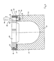
- Figure 1 shows a drainage channel in cross section, with a Gutter body 10 and a patch cover 20.
- the Channel body 10 has a U-shaped cross section.
- the channel cross-section can also be another form, for example have a V-shape.
- the gutter body 10 has Gutter walls 11, on the upper edges 12 a metallic Frame 13 for reinforcing the upper edge 12 and the support the cover 20 is used.
- the channel wall 11 has a franking 14, which with a franking 15 in the frame 13 corresponds.
- 15 is a Permanent magnet 30 frictionally inserted.
- the magnet 30 is additionally by the acting between it and the frame 13 magnetic field held in the clearances 14, 15. In the event that no frame rests on the channel body, is the magnet by means of a screw or rivets or through Gluing attached to the gutter body.
- an opening 22 is provided. Through the opening 22 can by means of an engaging tool 40 the magnetic field lines are deflected and thereby the magnetic holding forces are weakened.
- the Tool 40 consists of a permalloy alloy with very high permeability.
- a franking 23 in the cover 20 is formed on the opposite of the permanent magnet 30 body wall 11 .
- a projection 16 is provided, which at Placing the cover 20 on the channel body 10 in the Clearance 23 intervenes.
- the franking can also on be provided the frame and the projection accordingly the cover part.
- Figure 2 also shows a cross section through a drainage channel with on a gutter body 10 by magnets 30th attached cover 20.
- the gutter body also has like in Figure 1 shows a U-shaped cross section, wherein the cross-section is not limited to this shape only.
- the magnets are also as U-shaped Permanent magnets 30 are formed.
- the permanent magnets 30 are on the opposite sides of the two Gutter walls 11 arranged.
- the cover member 20 has openings 22, which correspond to the magnet interior.
- the Openings 22 are designed as passage openings in such a way that that the intervention of a tool 40 attenuated the magnetic field is and the cover 20 in a simple manner of the body is released.
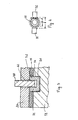
- Figure 3 shows an enlarged partial cross section along the Lines III-III through a drainage channel with a magnet 30, for fixing the cover member 20 on the gutter body 10.
- the magnet 30 is in a clearance 14 of the channel wall 11 and in a corresponding franking 15 in arranged the frame.
- the magnet has a U-shape, wherein the two magnetic legs 31 and 32 completely in the clearances are arranged.
- the opening 22 of the cover 20 has a width which is essentially the distance between the magnetic legs 31, 32 corresponds.
- a tool 40 which is tubular. Through the intervention of the tool 40, the field lines are deflected because the tool 40 made of a high permeability metallic alloy is. Thus, a so-called shield in the magnetic Field reached. The magnetic holding forces become weakened and the cover slightly removed.
- FIG. 4 shows a U-shaped permanent magnet according to FIG 3 with a between the two magnetic legs 31, 32 introduced Shielding tool 40.
- the shielding tool 40 has a tubular cross-section, wherein the outer diameter D of the tool 40 is smaller than the width b between the both magnetic legs 31 and 32 is. From the course of the magnetic field lines it can be seen that they are around the U-shaped Shielding tool 40 are bent and thus inside the Magnet creates a free space without magnetic effect. This known screening effect leads to the desired attenuation the magnetic holding forces.
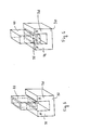
- Figure 5 shows a perspective view of a U-shaped Permanent magnets 30 with one between the two Magnetic limbs 31, 32 inserted tool 40.
- the tool 40 has the shape of a tube with a rectangular cross-section, wherein the base of the tube substantially the Dimensions of the magnet interior corresponds.
- Figure 6 shows a perspective view of a U-shaped Magnet 30 with a tool 40 for shorting of the magnetic field.
- the tool 40 is designed in such a way that at its end a rod-shaped permanent magnet 35th is attached. To release the lock, the tool engages 40 in the opening of the cover, with the poles of the two Magnets repel each other. Thus, the magnetic field "shorted" and solved the lock in a simple manner.
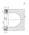
- FIG. 7 shows a cross section through a drainage channel with on a gutter body 10 with a permanent magnet 30th attached cover member 20 and an opposite engagement device 16, 23.
- the permanent magnet 30, which is formed as a bar magnet is in a recess 24th the cover 20 is attached.
- the frame 13 is made of metal.
Landscapes
- Health & Medical Sciences (AREA)
- Life Sciences & Earth Sciences (AREA)
- Engineering & Computer Science (AREA)
- Hydrology & Water Resources (AREA)
- Public Health (AREA)
- Water Supply & Treatment (AREA)
- Sewage (AREA)
- Water Treatment By Electricity Or Magnetism (AREA)
Description
- Figur 1
- einen Querschnitt durch eine Entwässerungsrinne mit auf einem Rinnenkörper durch einen Magneten befestigten Abdeckteil und einer gegenüberliegenden Eingriffsvorrichtung;
- Figur 2
- einen Querschnitt durch eine Entwässerungsrinne mit auf einem Rinnenkörper durch Magneten befestigten Abdeckteil;
- Figur 3
- einen vergrößerten Teil-Querschnitt entlang der Linien III-III gemäß Figur 1 mit eingesetztem Abschirmwerkzeug;
- Figur 4
- eine Draufsicht auf einen U-förmigen Magneten sowie einen eingesetzten rohrförmigen Abschirmwerkzeug zum Abschwächen des magnetischen Feldes zwischen den beiden Magnet-Polen;
- Figur 5
- eine perspektivische Darstellung eines U-förmigen Magneten, sowie eines stabförmigen Abschirmwerkzeuges viereckigem Querschnitt, zum Abschwächen des magnetischen Feldes;
- Figur 6
- eine perspektivische Darstellung eines U-förmigen Magneten mit einem Werkzeug zum Kurzschließen des magnetischen Feldes;
- Figur 7
- einen Querschnitt durch eine Entwässerungsrinne mit auf einem Rinnenkörper mit einem Stabmagneten befestigten Abdeckteil und einer gegenüberliegenden Eingriffsvorrichtung.
- 10
- Körper
- 11
- Körperwand
- 12
- Oberrand
- 13
- Zarge
- 14
- Freimachung
- 15
- Freimachung in der Zarge
- 16
- Vorsprung
- 20
- Abdeckteil
- 21
- Kantenbereich
- 22
- Öffnung
- 23
- Freimachung
- 24
- Ausnehmung
- 30
- Permanent-Magnet
- 31, 32
- Magnet-Schenkel
- 33, 34
- Stirnflächen
- 35
- Stabmagnet
- 40
- Werkzeug
Claims (11)
- Oberflächen-Entwässerungs-Anordnung, insbesondere Entwässerungsrinne, Straßenablauf, Hofablauf oder Schachtabdeckung, umfassend einen im Boden einbaubaren Körper (10), ein auf einem Oberrand (12) des Körpers (10) befestigbares Abdeckteil (20) und mindestens ein Befestigungselement (30) zum Befestigen des Abdeckteils (20) auf dem Körper (10),
wobei das Befestigungselement (30) ein Permanent-Magnet ist,
dadurch gekennzeichnet,dass
der Permanentmagnet (30) ein U-förmiger Permanentmagnet ist, wobei das Magnetinnere, welches durch gegengepolte Magnetschenkel (31, 32) gebildet ist, mit einer Öffnung (22) in dem Abdeckteil (20) korrespondiert, zum Einsetzen eines Werkzeugs (40) zum Abschwächen des magnetischen Feldes und zum Lösen der Arretierung. - Oberflächen-Entwässerungs-Anordnung nach Anspruch 1,
dadurch gekennzeichnet, dass
der Permanent-Magnet (30) in einer an einem oberen Bereich einer Körperwand (11) vorgesehenen Freimachung (14) angeordnet ist, wobei der Permanent-Magnet(30) durch Einstecken oder Nieten in der Freimachung (14) befestigbar ist. - Oberflächen-Entwässerungs-Anordnung nach einem der vorangehenden Ansprüche, insbesondere nach Anspruch 1,
dadurch gekennzeichnet, dass
der Permanent-Magnet (30) in einer am Abdeckteil (20) vorgesehenen Ausnehmung (24) angeordnet ist, wobei der Permanent-Magnet (30) durch Einstecken oder Nieten in der Ausnehmung (24) befestigbar ist. - Oberflächen-Entwässerungs-Anordnung nach einem der vorangehenden Ansprüche, insbesondere nach Anspruch 1,
dadurch gekennzeichnet,dass
der Permanent-Magnet (30) in einer Freimachung (15) einer vorzugsweise aus Metall bestehenden Zarge (13) angebracht ist, welche zur Auflage des Abdeckteils (20) als Verstärkung des Oberrandes (12) des Körpers (10) vorgesehen ist. - Oberflächen-Entwässerungs-Anordnung nach Anspruch 2 oder 4,
dadurch gekennzeichnet,dass
die Freimachung (14, 15) in dem Körper (10) bzw. in der Zarge (13) derart dimensioniert ist, dass der Permanent-Magnet (30) vollständig in der Freimachung (14, 15) angebracht ist, wobei die Stirnflächen (33, 34) der Magnetschenkel (31, 32) mit dem Abdeckteil (20) korrespondieren. - Oberflächen-Entwässerungs-Anordnung nach einem der vorangehenden Ansprüche,
dadurch gekennzeichnet,dass
die Öffnung (22) des Abdeckteils (20) als eine Durchgangsöffnung ausgebildet ist. - Oberflächen-Entwässerungs-Anordnung nach Anspruch 6,
dadurch gekennzeichnet,dass
die Durchgangsöffnung (22) im Oberflächenbereich mit einer Dichtung versehen ist. - Oberflächen-Entwässerungs-Anordnung nach einem der vorangehenden Ansprüche,
dadurch gekennzeichnet,dass
das Werkzeug (40) zum Abschwächen des magnetischen Feldes ein Abschirmrohr mit kreis- oder viereckförmigen Querschnitt ist, mit einem Außendurchmesser D, welcher kleiner als der Abstand b zwischen den beiden Magnetschenkeln (31, 32) ist. - Oberflächen-Entwässerungs-Anordnung nach einem der vorangehenden Ansprüche,
dadurch gekennzeichnet,dass
das Werkzeug (40) aus einer metallischen Legierung mit hoher Permeabilität hergestellt ist. - Oberflächen-Entwässerungs-Anordnung nach einem der vorangehenden Ansprüche,
dadurch gekennzeichnet,dass
das Werkzeug (30) zum Abschwächen des magnetischen Feldes an einem Ende einen Stabmagneten (35) aufweist, wobei die Länge l des Stabmagneten (35) im wesentlichen die Breite b des Inneren des U-förmigen Permanent-Magneten (30) entspricht. - Oberflächen-Entwässerungs-Anordnung nach einem der vorangehenden Ansprüche, insbesondere nach Anspruch 1,
dadurch gekennzeichnet,dass
gegenüber dem Permanent-Magneten (30) an dem Abdeckteil (20) und am Körper (10) eine Freimachung (23) bzw. ein in diese eingreifender Vorsprung (16) als unöffenbare Befestigungseinrichtung zum Halten des Abdeckteils (20) auf dem Körper (10) vorgesehen sind.
Applications Claiming Priority (3)
| Application Number | Priority Date | Filing Date | Title |
|---|---|---|---|
| DE10112842 | 2001-03-16 | ||
| DE2001112842 DE10112842B4 (de) | 2001-03-16 | 2001-03-16 | Oberflächen-Entwässerungs-Anordnung |
| PCT/EP2002/002907 WO2002075065A1 (de) | 2001-03-16 | 2002-03-15 | Oberflächen-entwässerungs-anordnung |
Publications (2)
| Publication Number | Publication Date |
|---|---|
| EP1368543A1 EP1368543A1 (de) | 2003-12-10 |
| EP1368543B1 true EP1368543B1 (de) | 2005-11-09 |
Family
ID=7677798
Family Applications (1)
| Application Number | Title | Priority Date | Filing Date |
|---|---|---|---|
| EP02706764A Expired - Lifetime EP1368543B1 (de) | 2001-03-16 | 2002-03-15 | Oberflächen-entwässerungs-anordnung |
Country Status (4)
| Country | Link |
|---|---|
| EP (1) | EP1368543B1 (de) |
| DE (2) | DE10112842B4 (de) |
| ES (1) | ES2252429T3 (de) |
| WO (1) | WO2002075065A1 (de) |
Families Citing this family (5)
| Publication number | Priority date | Publication date | Assignee | Title |
|---|---|---|---|---|
| NL1031302C2 (nl) * | 2006-03-03 | 2007-09-04 | Struyk Verwo Groep B V | Bestratingsput met grendelinrichting. |
| CN102505754B (zh) * | 2006-08-17 | 2015-01-14 | 北京四方如钢混凝土制品有限公司 | 线性排水u型槽组件 |
| CN103526819A (zh) * | 2013-09-16 | 2014-01-22 | 安徽华普节能房屋材料有限责任公司 | 卵形槽排水管道 |
| CN106087783B (zh) * | 2016-06-03 | 2018-08-21 | 重庆交通大学 | 一种泥石流区u型涵洞水力断面尺寸设计方法 |
| CN110629701A (zh) * | 2019-09-06 | 2019-12-31 | 中国建筑第八工程局有限公司 | 车辆限流桩及其施工方法 |
Family Cites Families (3)
| Publication number | Priority date | Publication date | Assignee | Title |
|---|---|---|---|---|
| DE2633444A1 (de) * | 1976-07-24 | 1978-01-26 | Buderus Eisenwerk | Ablauf mit rahmen und einsetzbarem rost |
| JP2000240084A (ja) * | 1999-02-24 | 2000-09-05 | Chikatan:Kk | マンホールの蓋構造 |
| JP4169430B2 (ja) * | 1999-04-14 | 2008-10-22 | 日之出水道機器株式会社 | マンホール蓋における蓋板の貫通孔の閉止構造 |
-
2001
- 2001-03-16 DE DE2001112842 patent/DE10112842B4/de not_active Expired - Fee Related
-
2002
- 2002-03-15 DE DE50204864T patent/DE50204864D1/de not_active Expired - Fee Related
- 2002-03-15 ES ES02706764T patent/ES2252429T3/es not_active Expired - Lifetime
- 2002-03-15 EP EP02706764A patent/EP1368543B1/de not_active Expired - Lifetime
- 2002-03-15 WO PCT/EP2002/002907 patent/WO2002075065A1/de not_active Ceased
Also Published As
| Publication number | Publication date |
|---|---|
| DE50204864D1 (de) | 2005-12-15 |
| EP1368543A1 (de) | 2003-12-10 |
| DE10112842A1 (de) | 2003-02-20 |
| DE10112842B4 (de) | 2004-05-27 |
| WO2002075065A1 (de) | 2002-09-26 |
| ES2252429T3 (es) | 2006-05-16 |
Similar Documents
| Publication | Publication Date | Title |
|---|---|---|
| EP1383967B1 (de) | Abdeckung für eine entwässerungseinrichtung | |
| DE4330102C2 (de) | Verbindungselement | |
| DE69509928T2 (de) | Verbesserungen an Verriegelungsringen | |
| EP0379722B1 (de) | Aus Kunststoff bestehendes Halteelement | |
| DE202010012567U1 (de) | Seilumlenkstück für einen Seilfensterheber | |
| EP0261265B1 (de) | Stangenführung für die Flachbandstangen eines Stangenverschlusses | |
| DE3942774C2 (de) | Gehäuse für Verschlüsse, Stellhebel, Durchführungen od. dgl., zur Montage in einem Durchbruch in einer dünnen, elektrisch leitenden Wand, wie Blechschranktür oder Maschinengehäusedeckel | |
| DE102010028610A1 (de) | Wischermotor mit Entkopplungselement und Entkopplungselement | |
| DE10112842B4 (de) | Oberflächen-Entwässerungs-Anordnung | |
| EP1597441B1 (de) | Entw sserungsvorrichtung | |
| DE10112840C1 (de) | Entwässerungseinrichtung zur Oberflächenentwässerung | |
| DE19924767A1 (de) | Elektromagnetisches Stellglied | |
| AT408561B (de) | Schutzzaun | |
| DE20315709U1 (de) | Deckel einer Schachtabdeckung sowie Schachtabdeckung | |
| DE2933310C2 (de) | ||
| EP1023515B1 (de) | Tür- oder fensterband | |
| DE10208729B4 (de) | Befestigungsanordnung und Oberflächenentwässerungs-Einrichtung | |
| EP1311737A1 (de) | Abstandsveränderbarer schliessbügel für drehfallenverschlüsse | |
| DE10130920A1 (de) | Abdeckung für eine Entwässerungseinrichtung | |
| EP3680927A1 (de) | Schlüsselschalter | |
| EP1103676A1 (de) | Treibstangenschloss | |
| EP4394157B1 (de) | Profil mit integriertem schaltelement einer schaltung | |
| EP1622239B1 (de) | Betätiger insbesondere für Fahrzeuge mit einem, mit einem Kabel versehenen, elektrischen Bauteil | |
| EP0651164A1 (de) | Mobiltelefon mit Befestigungsvorrichtung | |
| EP3665395B1 (de) | Schelle zum befestigen eines rohr- oder schlauchförmigen gegenstands |
Legal Events
| Date | Code | Title | Description |
|---|---|---|---|
| PUAI | Public reference made under article 153(3) epc to a published international application that has entered the european phase |
Free format text: ORIGINAL CODE: 0009012 |
|
| 17P | Request for examination filed |
Effective date: 20030822 |
|
| AK | Designated contracting states |
Kind code of ref document: A1 Designated state(s): AT BE CH CY DE DK ES FI FR GB GR IE IT LI LU MC NL PT SE TR |
|
| RIN1 | Information on inventor provided before grant (corrected) |
Inventor name: TILING, WOLF Inventor name: RINCKENS, MANFRED |
|
| 17Q | First examination report despatched |
Effective date: 20040503 |
|
| GRAP | Despatch of communication of intention to grant a patent |
Free format text: ORIGINAL CODE: EPIDOSNIGR1 |
|
| GRAP | Despatch of communication of intention to grant a patent |
Free format text: ORIGINAL CODE: EPIDOSNIGR1 |
|
| GRAP | Despatch of communication of intention to grant a patent |
Free format text: ORIGINAL CODE: EPIDOSNIGR1 |
|
| RBV | Designated contracting states (corrected) |
Designated state(s): DE ES FR GB IT |
|
| GRAS | Grant fee paid |
Free format text: ORIGINAL CODE: EPIDOSNIGR3 |
|
| GRAA | (expected) grant |
Free format text: ORIGINAL CODE: 0009210 |
|
| AK | Designated contracting states |
Kind code of ref document: B1 Designated state(s): DE ES FR GB IT |
|
| REG | Reference to a national code |
Ref country code: GB Ref legal event code: FG4D Free format text: NOT ENGLISH |
|
| REF | Corresponds to: |
Ref document number: 50204864 Country of ref document: DE Date of ref document: 20051215 Kind code of ref document: P |
|
| GBT | Gb: translation of ep patent filed (gb section 77(6)(a)/1977) |
Effective date: 20060222 |
|
| REG | Reference to a national code |
Ref country code: ES Ref legal event code: FG2A Ref document number: 2252429 Country of ref document: ES Kind code of ref document: T3 |
|
| ET | Fr: translation filed | ||
| PLBE | No opposition filed within time limit |
Free format text: ORIGINAL CODE: 0009261 |
|
| STAA | Information on the status of an ep patent application or granted ep patent |
Free format text: STATUS: NO OPPOSITION FILED WITHIN TIME LIMIT |
|
| 26N | No opposition filed |
Effective date: 20060810 |
|
| PGFP | Annual fee paid to national office [announced via postgrant information from national office to epo] |
Ref country code: ES Payment date: 20080325 Year of fee payment: 7 |
|
| PGFP | Annual fee paid to national office [announced via postgrant information from national office to epo] |
Ref country code: GB Payment date: 20080331 Year of fee payment: 7 Ref country code: IT Payment date: 20080312 Year of fee payment: 7 |
|
| PGFP | Annual fee paid to national office [announced via postgrant information from national office to epo] |
Ref country code: DE Payment date: 20080528 Year of fee payment: 7 |
|
| PGFP | Annual fee paid to national office [announced via postgrant information from national office to epo] |
Ref country code: FR Payment date: 20080328 Year of fee payment: 7 |
|
| GBPC | Gb: european patent ceased through non-payment of renewal fee |
Effective date: 20090315 |
|
| REG | Reference to a national code |
Ref country code: FR Ref legal event code: ST Effective date: 20091130 |
|
| PG25 | Lapsed in a contracting state [announced via postgrant information from national office to epo] |
Ref country code: DE Free format text: LAPSE BECAUSE OF NON-PAYMENT OF DUE FEES Effective date: 20091001 |
|
| PG25 | Lapsed in a contracting state [announced via postgrant information from national office to epo] |
Ref country code: GB Free format text: LAPSE BECAUSE OF NON-PAYMENT OF DUE FEES Effective date: 20090315 Ref country code: FR Free format text: LAPSE BECAUSE OF NON-PAYMENT OF DUE FEES Effective date: 20091123 |
|
| REG | Reference to a national code |
Ref country code: ES Ref legal event code: FD2A Effective date: 20090316 |
|
| PG25 | Lapsed in a contracting state [announced via postgrant information from national office to epo] |
Ref country code: ES Free format text: LAPSE BECAUSE OF NON-PAYMENT OF DUE FEES Effective date: 20090316 |
|
| PG25 | Lapsed in a contracting state [announced via postgrant information from national office to epo] |
Ref country code: IT Free format text: LAPSE BECAUSE OF NON-PAYMENT OF DUE FEES Effective date: 20090315 |