EP1367929B1 - Kehrgerät - Google Patents
Kehrgerät Download PDFInfo
- Publication number
- EP1367929B1 EP1367929B1 EP02719950A EP02719950A EP1367929B1 EP 1367929 B1 EP1367929 B1 EP 1367929B1 EP 02719950 A EP02719950 A EP 02719950A EP 02719950 A EP02719950 A EP 02719950A EP 1367929 B1 EP1367929 B1 EP 1367929B1
- Authority
- EP
- European Patent Office
- Prior art keywords
- sweeping
- appliance according
- dirt
- sill
- floor surface
- Prior art date
- Legal status (The legal status is an assumption and is not a legal conclusion. Google has not performed a legal analysis and makes no representation as to the accuracy of the status listed.)
- Expired - Lifetime
Links
Images


Classifications
-
- A—HUMAN NECESSITIES
- A47—FURNITURE; DOMESTIC ARTICLES OR APPLIANCES; COFFEE MILLS; SPICE MILLS; SUCTION CLEANERS IN GENERAL
- A47L—DOMESTIC WASHING OR CLEANING; SUCTION CLEANERS IN GENERAL
- A47L5/00—Structural features of suction cleaners
- A47L5/12—Structural features of suction cleaners with power-driven air-pumps or air-compressors, e.g. driven by motor vehicle engine vacuum
- A47L5/22—Structural features of suction cleaners with power-driven air-pumps or air-compressors, e.g. driven by motor vehicle engine vacuum with rotary fans
- A47L5/28—Suction cleaners with handles and nozzles fixed on the casings, e.g. wheeled suction cleaners with steering handle
- A47L5/34—Suction cleaners with handles and nozzles fixed on the casings, e.g. wheeled suction cleaners with steering handle with height adjustment of nozzles or dust-loosening tools
-
- A—HUMAN NECESSITIES
- A47—FURNITURE; DOMESTIC ARTICLES OR APPLIANCES; COFFEE MILLS; SPICE MILLS; SUCTION CLEANERS IN GENERAL
- A47L—DOMESTIC WASHING OR CLEANING; SUCTION CLEANERS IN GENERAL
- A47L11/00—Machines for cleaning floors, carpets, furniture, walls, or wall coverings
- A47L11/02—Floor surfacing or polishing machines
- A47L11/20—Floor surfacing or polishing machines combined with vacuum cleaning devices
- A47L11/202—Floor surfacing or polishing machines combined with vacuum cleaning devices having separate drive for the cleaning brushes
-
- A—HUMAN NECESSITIES
- A47—FURNITURE; DOMESTIC ARTICLES OR APPLIANCES; COFFEE MILLS; SPICE MILLS; SUCTION CLEANERS IN GENERAL
- A47L—DOMESTIC WASHING OR CLEANING; SUCTION CLEANERS IN GENERAL
- A47L11/00—Machines for cleaning floors, carpets, furniture, walls, or wall coverings
- A47L11/24—Floor-sweeping machines, motor-driven
-
- A—HUMAN NECESSITIES
- A47—FURNITURE; DOMESTIC ARTICLES OR APPLIANCES; COFFEE MILLS; SPICE MILLS; SUCTION CLEANERS IN GENERAL
- A47L—DOMESTIC WASHING OR CLEANING; SUCTION CLEANERS IN GENERAL
- A47L11/00—Machines for cleaning floors, carpets, furniture, walls, or wall coverings
- A47L11/32—Carpet-sweepers
-
- A—HUMAN NECESSITIES
- A47—FURNITURE; DOMESTIC ARTICLES OR APPLIANCES; COFFEE MILLS; SPICE MILLS; SUCTION CLEANERS IN GENERAL
- A47L—DOMESTIC WASHING OR CLEANING; SUCTION CLEANERS IN GENERAL
- A47L11/00—Machines for cleaning floors, carpets, furniture, walls, or wall coverings
- A47L11/40—Parts or details of machines not provided for in groups A47L11/02 - A47L11/38, or not restricted to one of these groups, e.g. handles, arrangements of switches, skirts, buffers, levers
- A47L11/4013—Contaminants collecting devices, i.e. hoppers, tanks or the like
-
- A—HUMAN NECESSITIES
- A47—FURNITURE; DOMESTIC ARTICLES OR APPLIANCES; COFFEE MILLS; SPICE MILLS; SUCTION CLEANERS IN GENERAL
- A47L—DOMESTIC WASHING OR CLEANING; SUCTION CLEANERS IN GENERAL
- A47L11/00—Machines for cleaning floors, carpets, furniture, walls, or wall coverings
- A47L11/40—Parts or details of machines not provided for in groups A47L11/02 - A47L11/38, or not restricted to one of these groups, e.g. handles, arrangements of switches, skirts, buffers, levers
- A47L11/4027—Filtering or separating contaminants or debris
-
- A—HUMAN NECESSITIES
- A47—FURNITURE; DOMESTIC ARTICLES OR APPLIANCES; COFFEE MILLS; SPICE MILLS; SUCTION CLEANERS IN GENERAL
- A47L—DOMESTIC WASHING OR CLEANING; SUCTION CLEANERS IN GENERAL
- A47L11/00—Machines for cleaning floors, carpets, furniture, walls, or wall coverings
- A47L11/40—Parts or details of machines not provided for in groups A47L11/02 - A47L11/38, or not restricted to one of these groups, e.g. handles, arrangements of switches, skirts, buffers, levers
- A47L11/4036—Parts or details of the surface treating tools
- A47L11/4041—Roll shaped surface treating tools
-
- A—HUMAN NECESSITIES
- A47—FURNITURE; DOMESTIC ARTICLES OR APPLIANCES; COFFEE MILLS; SPICE MILLS; SUCTION CLEANERS IN GENERAL
- A47L—DOMESTIC WASHING OR CLEANING; SUCTION CLEANERS IN GENERAL
- A47L11/00—Machines for cleaning floors, carpets, furniture, walls, or wall coverings
- A47L11/40—Parts or details of machines not provided for in groups A47L11/02 - A47L11/38, or not restricted to one of these groups, e.g. handles, arrangements of switches, skirts, buffers, levers
- A47L11/4036—Parts or details of the surface treating tools
- A47L11/4044—Vacuuming or pick-up tools; Squeegees
Definitions
- the invention relates to a sweeper for carpet and hard floor cleaning comprising a housing, a dirt collecting container, a Has dirt inlet opening, and one of the dirt inlet opening adjacently disposed, rotatably drivable brush roller, wherein the brush roller at the dirt inlet opening a sweeping threshold is assigned, via the dirt particles in the dirt collector are convertible, and wherein the sweeping threshold in the direction of the to be cleaned bottom surface is adjustably held on the housing.
- Such sweepers allow cleaning of both carpets as well as of Nartböden. Dirt particles can from here the brush roller detected and the sweeping threshold in the dirt collector to be thrown.
- the Kehrschwelle is here a occupy the smallest possible distance to the floor surface to be cleaned, so that it can be prevented that of the brush roller detected dirt particles are thrown under the sweeping threshold.
- a sweeper of the beginning mentioned type in which in a housing transverse to the direction of movement of the sweeping device is arranged a cylindrical brush.
- the brush axis is mounted in the side walls of the housing and At the axle ends two wheels are held against rotation, the Diameter is smaller than the diameter of the brush.
- Behind the Brush is arranged a swingably mounted sump whose parallel to the brush edge, both very close to the contact area the bristles of the brush with the floor surface to be swept as well as very close to this surface itself.
- Object of the present invention is a sweeper of the generic Form such a way that a hindrance to the forward movement sweeper avoided by the sweeping threshold becomes.
- the sweeping threshold is an actuator is assigned to the positioning of the Kehrschwelle in a minimum distance to the bottom surface when approaching the housing to the bottom surface.
- the sweeping threshold can be independent of the nature of the floor surface, so both in the cleaning of a relatively soft carpet as well as a hard floor, be kept at a minimum distance from the ground surface.
- the sweeping threshold can thus be adjusted in their distance from the ground surface be, so that snagging the sweeping threshold, for example, with a carpet by appropriate positioning of the sweeping threshold can be reliably prevented above the carpet.
- the sweeping threshold is adjustably held on the housing. This makes possible In particular, an embodiment in which the Kehrschwelle relative to Brush roller is movably arranged so that when cleaning a Carpeting while the brush roller sinks slightly into the carpet, however, the sweeping threshold slides over the fibers of the carpet.
- the actuator mechanical contact elements has, which falls below the minimum distance between the Sweeper and the floor surface contact the floor surface and keep the sweeping threshold at a distance to the ground surface.
- the minimum distance is preferably about 0.3 to about 0.7 mm, in particular about 0.5 mm.
- the contact elements for example, as freely rotatable on the Kehrschwelle mounted contact rollers be formed.
- the contact elements than below the minimum distance between Sweeper and floor surface along the floor surface sliding skids are formed.
- the sweeper is designed to be movable and drive wheels and / or support rollers, wherein the skids relative to the cleansing floor area above the floor surface contacting Peripheral region of the drive wheels and / or support rollers are held. This has the consequence that the skids when cleaning a hard floor spaced to the floor surface when cleaning a carpet however, slide along the carpet while the drive wheels and / or support rollers due to the weight of the sweeper something sink into the carpet.
- adjustable support of the Kehrschwelle can be a guide to Are used, where the Kehrschwelle is held displaceable.
- the sweeping threshold about a parallel to the axis of rotation of the brush roller aligned Swivel axis is pivotable.
- This can be the Kehrschwelle held on at least one pivotally mounted pivot arm be, which is preferably articulated on the rigidly formed housing.
- the above-described mechanical on the swivel arm Contact elements held. It is advantageous if the Contact elements are integrally connected to the pivot arm. For this purpose, it is advantageous if the swivel arm falls below a minimum distance between Kehrschwelle and ground surface the Having bottom surface contacting sliding surface.
- Sweeper In a mechanically particularly resilient embodiment of the invention Sweeper is provided that the sweeper two has pivotally mounted pivot arms, at the free ends the turning threshold is maintained. It is favorable if the two Swivel arms arranged outside the dirt inlet opening are, for example, absorb the dirt inlet between them. Such a positioning of the pivot arms has the consequence that the dirt inlet opening one of the position of the pivot arms has unaffected geometry and consequently the shape of the Dirt inlet is independent of the position of the pivot arms.
- the sweeping threshold can in such an embodiment against the action of an elastic restoring force in Direction be adjusted to the housing of the sweeper, but where it is ensured that the sweeping threshold in case of elimination of external Forces a defined position relative to the housing occupies.
- a spring element for example, a leaf spring or a coil spring be used. It has proved to be particularly favorable when the spring element of a rubber-like material, preferably made of an elastomer.
- the spring element is advantageously at the dirt collecting container held, which is preferably rigidly connected to the housing.
- the spring element one between the sweeping threshold and the dirt collector arranged arranged flexible seal. This makes possible a dust-tight seal of the dirt collection in the Range of adjustable Kehrschwelle.
- the seal forms at least one sealing lip, the can be applied to a wall of the dirt collecting container.
- the sweeping device is designed as a sweeper and this one via a suction channel with the dirt collector and the dirt entry port in fluid communication Suction turbine has.
- a suction flow be generated, the transfer of the dirt particles from the Supported dirt inlet in the dirt collector.
- a dirt filter is arranged in the suction channel is and the suction channel upstream of the dirt filter the Dirt collecting container forms. This allows for a special compact design of the sweeping device, as a separate dirt collector is not mandatory.
- the sweeper designed to be movable is, wherein the dirt inlet opening of the floor surface to be cleaned facing in a front in the direction of travel sweeper is arranged while the suction turbine in a respect to the Direction of travel rear end of the sweeper is positioned, and that the suction channel is oriented substantially horizontally and the Suction inlet connects with an inlet opening of the suction turbine.
- the suction channel can hold means for holding the dirt filter include, so that upstream of the holding means and the dirt filter extending portion of the suction channel the dirt collector formed.
- the suction channel is detachably connectable to the housing held bottom plate, held at the sweeping threshold is.
- the bottom plate allows access to the suction channel to Replacing the dirt filter and possibly emptying the Dirt collection.
- the drive of the brush roller can be done by means of an electric motor, wherein the electric motor preferably connectable to a rechargeable voltage source is.
- the contact pressure of the brush roller to be cleaned Floor surface is controllable. So it has proved to be favorable if the brush roller in the direction of the bottom surface adjustable on the housing is held, wherein the adjustment of the position of the brush roller is independent of the adjustment of the position of the sweeping roller. This gives the possibility of the sweeping roller - as described above - in a minimum distance to the bottom surface while the brush roller to achieve an improved cleaning effect in the Cleaning a carpet can sink something into the carpet.
- the brush roller for example, by means of obliquely or parallel to Vertical aligned guide elements slidably on the housing be held.
- the brush roller on a pivoting member about a parallel to the axis of rotation of the brush roller aligned Swivel axis is pivotally mounted on the housing.
- the pivot member comprises a drive housing for receiving a electric brush drive motor and an electrical power source. This allows a pre-assembly of the brush drive in the drive housing, then preferably on the housing of the sweeper detachably connectable mountable.
- the pivoting member placed on the bottom surface Skids includes for holding the brush roller in a predetermined Position to the ground surface.
- the skids of the pivot member relative to the floor surface to be cleaned above are held by drive and / or support wheels of the sweeper, so that the skids of the pivot member when cleaning a hard floor spaced to the bottom surface, but in the cleaning of a Carpet due to the sinking of the drive and / or support wheels glide along the carpet.
- the sweeping device is self-propelled.
- the sweeper comprise a chassis, which is preferably integral with the housing is formed, and on the at least two drive wheels are rotatably mounted, by means of at least one electric drive motor are drivable.
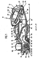
- the housing surrounds a suction channel 16 and includes a support plate 20, which is aligned parallel to a bottom surface 18 and to which in the direction of travel 21 of the sweeping device 10, a step 22 connects, via the support plate 20 is integrally connected to a support plate 23, to which one of the bottom surface 18 facing end wall 24 connects.
- the housing 12 comprises a Bottom plate 26, which is shown in particular in Figures 2 and 3 and to which an end plate 28 adjoins opposite to the direction of travel 21.
- the housing 12 In its rear region, the housing 12 carries a suction turbine 30 with a turbine housing 31, the housing lower part 32 and an upper housing part 33 and a turbine wheel 34 and a Turbine drive motor 35 receives.
- the turbine engine 35 By means of the turbine engine 35, the turbine wheel 34 to a rotational movement about a driven obliquely to the vertical turbine axis 36 driven become.
- the turbine wheel is adjacent to the housing bottom 32nd an intake manifold 37 formed over which the suction turbine 30 with the Suction channel 16 is in flow communication.
- the bottom plate 26 is detachably connectable to the end wall 24 and the Support plate 20 held.
- the bottom plate 26 defines below the support plate 23 a Dirt inlet opening 42, which is aligned parallel to the direction of travel 21 Longitudinal walls 43, 44 and transverse to the direction 21 aligned front and rear transverse walls 45 and 46 limited becomes.
- skids 52 and 53 In the direction of travel 21 in front of the rear transverse wall 26 dives into the Schmutzeineriesö réelle 42 a Kehrschwelle 50, the free End of laterally outside of the dirt inlet opening 42 to the Longitudinal walls 43 and 44 arranged skids 52 and 53 held is.
- the skids 52, 53 each form a pivot arm, the In Height of the front transverse wall 45 at a laterally projecting Pivot pin 55 articulated and a transverse to the direction of travel 21st aligned pivot axis 56 is pivotable.
- the skids 52, 53 are in the direction of the Floor surface 18 arcuately curved and form with their the bottom surface 18 facing bottom a sliding surface 57th
- the sweeping threshold 50 is over a the entire width of the bottom plate 26 engaging, resilient Elastomeric seal 59 hinged to the bottom plate 26, wherein the elastomeric seal 59 an elastic restoring force on the sweeping threshold 50 exerts when it is pressed into the dirt inlet opening 52 becomes.
- the elastomeric seal 59 forms in its on the guide walls 47 and 48 adjoining lateral end regions in each case a sealing lip 60, which is a dust-tight seal of the suction channel 16 in the area between the bottom plate 18 and the sweeper 50 ensure.
- the dirt inlet opening 42 adjacent is within the suction channel 16 with transversely to the direction of travel 21 aligned axis of rotation 62 a Brush roller 63 is arranged, which shown in Figure 4 strongly schematized is.
- the brush roller 63 includes radially projecting sweeping brushes 64, the Pass through dirt inlet 42 and dirt particles from the Record bottom surface 18 and the sweeping threshold 50 in the suction channel 16 fling.
- the dirt absorption is in this case of the suction flow supported, which is caused by the suction turbine 30.
- the sweeper 10 comprises an above the support plate 23 arranged drive unit 66, in particular is shown in Figures 4 and 5.
- the drive unit 66 comprises a substantially cylindrically shaped drive housing 67, a drive motor 68 and rechargeable batteries 69 receives. Front side are projecting down to the drive housing 67 Retaining arms 70, 71 integrally formed, the support plate 23 laterally enclose and store at their free ends the brush roller 63, which known per se and therefore not shown in the drawing Transmission means, which are positioned in the support arm 70, with the Drive motor 68 is coupled.
- the holder of the drive unit 66 via integrally with the free ends of the support arms 70 and 71 connected lever arms 73, the with their free end on integrally molded bearing sleeves 74 are laterally hinged to the housing 12 integrally formed bearing pin 75.
- the bearing pins 75 in this case define a transverse to the direction of travel 21st and parallel to the brush roller 63 aligned pivot axis 76th (see Figure 5).
- the drive housing 67 forms in combination with the front side molded Retaining arms 70 and 71 and the lever arms fixed thereto 73 a pivot member 78 for pivotally mounting the Brush roller 63.
- the bottom surface is attached to the surface 18 facing free ends of the support arms 70 and 71 skids 80 molded.
- Support rollers 82, 83 freely rotatably mounted, with which the sweeping device 10 can be supported on the floor surface 18 to be cleaned.
- a hard floor is cleaned by means of the sweeping device 10, it will support itself the drive unit 66 via a not shown in the drawing Compression spring on the support plate 23 from, without this, the skids 80 touch the bottom surface 18. Also, the skids 52 and 53, at the the sweeping threshold 50 is held, take a position in this case at a distance to the bottom surface 18 a. Is by means of the sweeping device 10th However, a relatively soft bottom surface 18 cleaned, for example a carpet, so this fall the drive wheels 14th and the support rollers 82 and 83 in the bottom surface 18 to be cleaned a, as illustrated in FIG.
Landscapes
- Nozzles For Electric Vacuum Cleaners (AREA)
- Reciprocating, Oscillating Or Vibrating Motors (AREA)
- Polarising Elements (AREA)
- Automatic Analysis And Handling Materials Therefor (AREA)
- Vehicle Body Suspensions (AREA)
- Detergent Compositions (AREA)
Description
- Figur 1:
- eine schematische Längsschnittansicht eines Kehrgerätes;
- Figur 2:
- eine schematische schaubildliche Darstellung einer Bodenplatte des Kehrgerätes;
- Figur 3:
- eine Seitenansicht der Bodenplatte gemäß Figur 2 mit eingesetzter Bürstenwalze;
- Figur 4:
- eine schaubildliche schematische Darstellung der Bürstenwalze mit zugeordneter Bürstenantriebseinheit und
- Figur 5:
- eine schematische Seitenansicht eines vorderen Bereiches des Kehrgerätes.
Claims (22)
- Kehrgerät zur Teppich- und Hartbodenreinigung umfassend ein Gehäuse (12), einen Schmutzsammelbehälter (89), der eine Schmutzeintrittsöffnung (42) aufweist, sowie eine der Schmutzeintrittsöffnung (42) benachbart angeordnete, drehend antreibbare Bürstenwalze (63), wobei der Bürstenwalze (63) an der Schmutzeintrittsöffnung (42) eine Kehrschwelle (50) zugeordnet ist, über die Schmutzteilchen in den Schmutzsammelbehälter (89) überführbar sind, und wobei die Kehrschwelle (50) in Richtung auf die zu reinigende Bodenfläche (18) verstellbar am Gehäuse (12) gehalten ist, dadurch gekennzeichnet, daß der Kehrschwelle (50) ein Stellglied (52, 53) zugeordnet ist zur Positionierung der Kehrschwelle (50) in einem Mindestabstand zur Bodenfläche (18) bei Annäherung des Gehäuses (12) an die Bodenfläche (18).
- Kehrgerät nach Anspruch 1, dadurch gekennzeichnet, daß das Stellglied mechanische Kontaktelemente (52, 53) aufweist, die bei Unterschreiten des Mindestabstandes zwischen der Kehrschwelle (50) und der Bodenfläche (18) die Bodenfläche (18) kontaktieren und die Kehrschwelle (50) im Abstand zur Bodenfläche (18) halten.
- Kehrgerät nach Anspruch 2, dadurch gekennzeichnet, daß die Kontaktelemente als bei Unterschreiten des Mindestabstandes zwischen Kehrschwelle (50) und Bodenfläche (18) entlang der Bodenfläche (18) gleitende Gleitkufen (52, 53) ausgebildet sind.
- Kehrgerät nach einem der voranstehenden Ansprüche, dadurch gekennzeichnet, daß die Kehrschwelle (50) um eine parallel zur Drehachse (62) der Bürstenwalze (63) ausgerichtete Schwenkachse (56) verschwenkbar ist.
- Kehrgerät nach einem der voranstehenden Ansprüche, dadurch gekennzeichnet, daß die Kehrschwelle (50) an mindestens einem verschwenkbar gelagerten Schwenkarm (52, 53) gehalten ist.
- Kehrgerät nach Anspruch 5, dadurch gekennzeichnet, daß der Schwenkarm (52, 53) eine bei Unterschreiten eines Mindestabstandes zwischen Kehrschwelle (50) und Bodenfläche (18) die Bodenfläche (18) kontaktierende Gleitfläche (57) aufweist.
- Kehrgerät nach Anspruch 6, dadurch gekennzeichnet, daß die Gleitfläche (57) in Richtung auf die Bodenfläche (18) über die Kehrschwelle (50) übersteht.
- Kehrgerät nach Anspruch 5, 6 oder 7, dadurch gekennzeichnet, daß das Kehrgerät (10) zwei verschwenkbar gelagerte Schwenkarme (52, 53) aufweist, an deren freien Enden die Kehrschwelle (50) gehalten ist.
- Kehrgerät nach Anspruch 8, dadurch gekennzeichnet, daß die beiden Schwenkarme (52, 53) außerhalb der Schmutzeintrittsöffnung (42) angeordnet sind.
- Kehrgerät nach einem der voranstehenden Ansprüche, dadurch gekennzeichnet, daß die Kehrschwelle (50) in Richtung auf die Bodenfläche (18) mittels eines Federelementes (59) elastisch vorgespannt ist.
- Kehrgerät nach Anspruch 10, dadurch gekennzeichnet, daß das Federelement (59) aus einem gummiartigen Material, vorzugsweise aus einem Elastomer, gefertigt ist.
- Kehrgerät nach Anspruch 10 oder 11, dadurch gekennzeichnet, daß das Federelement (59) am Schmutzsammelbehälter (89) gehalten ist.
- Kehrgerät nach Anspruch 10, 11 oder 12, dadurch gekennzeichnet, daß das Federelement eine zwischen der Kehrschwelle (50) und dem Schmutzsammelbehälter (89) angeordnete flexible Abdichtung (59) ausbildet.
- Kehrgerät nach einem der voranstehenden Ansprüche, dadurch gekennzeichnet, daß das Kehrgerät (10) eine über einen Saugkanal (16) und den Schmutzsammelbehälter (89) mit der Schmutzeintrittsöffnung (42) in Strömungsverbindung stehende Saugturbine (30) aufweist.
- Kehrgerät nach Anspruch 14, dadurch gekennzeichnet, daß im Saugkanal (16) ein Schmutzfilter (87) angeordnet ist und der Saugkanal (16) stromaufwärts des Schmutzfilters (87) den Schmutzsammelbehälter (89) ausbildet.
- Kehrgerät nach Anspruch 14 oder 15, dadurch gekennzeichnet, daß der Saugkanal (16) eine lösbar verbindbar gehaltene Bodenplatte (26) umfaßt, an der die Kehrschwelle (50) gehalten ist.
- Kehrgerät nach einem der voranstehenden Ansprüche, dadurch gekennzeichnet, daß die Bürstenwalze (63) in Richtung auf die Bodenfläche (18) verstellbar am Gehäuse (12) gehalten ist, wobei die Verstellung der Position der Bürstenwalze (63) unabhängig ist von der Verstellung der Position der Kehrschwelle (50).
- Kehrgerät nach Anspruch 17, dadurch gekennzeichnet, daß die Bürstenwalze (63) an einem Schwenkglied (78) um eine parallel zu der Drehachse (62) der Bürstenwalze (63) ausgerichtete Schwenkachse (76) verschwenkbar am Gehäuse (12) gehalten ist.
- Kehrgerät nach Anspruch 18, dadurch gekennzeichnet, daß das Schwenkglied (78) ein Antriebsgehäuse (67) umfaßt zur Aufnahme eines elektrischen Bürstenantriebsmotors (68) und einer elektrischen Spannungsquelle (69).
- Kehrgerät nach Anspruch 18 oder 19, dadurch gekennzeichnet, daß das Schwenkglied (78) auf die Bodenfläche (18) aufsetzbare Gleitkufen (80) umfaßt zum Halten der Bürstenwalze (63) in einer vorgegebenen Position zur Bodenfläche (18).
- Kehrgerät nach Anspruch 18, 19 oder 20, dadurch gekennzeichnet, daß das Schwenkglied (78) lösbar verbindbar am Gehäuse (12) gehalten ist.
- Kehrgerät nach einem der voranstehenden Ansprüche, dadurch gekennzeichnet, daß das Kehrgerät (10) selbstfahrend ausgestaltet ist.
Applications Claiming Priority (3)
| Application Number | Priority Date | Filing Date | Title |
|---|---|---|---|
| DE10110906A DE10110906A1 (de) | 2001-03-07 | 2001-03-07 | Kehrgerät |
| DE10110906 | 2001-03-07 | ||
| PCT/EP2002/002125 WO2002069775A2 (de) | 2001-03-07 | 2002-02-28 | Kehrgerät |
Publications (2)
| Publication Number | Publication Date |
|---|---|
| EP1367929A2 EP1367929A2 (de) | 2003-12-10 |
| EP1367929B1 true EP1367929B1 (de) | 2005-09-14 |
Family
ID=7676576
Family Applications (1)
| Application Number | Title | Priority Date | Filing Date |
|---|---|---|---|
| EP02719950A Expired - Lifetime EP1367929B1 (de) | 2001-03-07 | 2002-02-28 | Kehrgerät |
Country Status (6)
| Country | Link |
|---|---|
| EP (1) | EP1367929B1 (de) |
| CN (1) | CN1267050C (de) |
| AT (1) | ATE304312T1 (de) |
| AU (1) | AU2002251034A1 (de) |
| DE (2) | DE10110906A1 (de) |
| WO (1) | WO2002069775A2 (de) |
Families Citing this family (48)
| Publication number | Priority date | Publication date | Assignee | Title |
|---|---|---|---|---|
| US8788092B2 (en) | 2000-01-24 | 2014-07-22 | Irobot Corporation | Obstacle following sensor scheme for a mobile robot |
| US8412377B2 (en) | 2000-01-24 | 2013-04-02 | Irobot Corporation | Obstacle following sensor scheme for a mobile robot |
| US6956348B2 (en) | 2004-01-28 | 2005-10-18 | Irobot Corporation | Debris sensor for cleaning apparatus |
| US7571511B2 (en) | 2002-01-03 | 2009-08-11 | Irobot Corporation | Autonomous floor-cleaning robot |
| US6690134B1 (en) | 2001-01-24 | 2004-02-10 | Irobot Corporation | Method and system for robot localization and confinement |
| US8396592B2 (en) | 2001-06-12 | 2013-03-12 | Irobot Corporation | Method and system for multi-mode coverage for an autonomous robot |
| US7429843B2 (en) | 2001-06-12 | 2008-09-30 | Irobot Corporation | Method and system for multi-mode coverage for an autonomous robot |
| DE10242257C5 (de) * | 2001-09-14 | 2017-05-11 | Vorwerk & Co. Interholding Gmbh | Selbsttätig verfahrbares Bodenstaub-Aufsammelgerät, sowie Kombination eines derartigen Aufsammelgerätes und einer Basisstation |
| US9128486B2 (en) | 2002-01-24 | 2015-09-08 | Irobot Corporation | Navigational control system for a robotic device |
| US8428778B2 (en) | 2002-09-13 | 2013-04-23 | Irobot Corporation | Navigational control system for a robotic device |
| US8386081B2 (en) | 2002-09-13 | 2013-02-26 | Irobot Corporation | Navigational control system for a robotic device |
| US7332890B2 (en) | 2004-01-21 | 2008-02-19 | Irobot Corporation | Autonomous robot auto-docking and energy management systems and methods |
| DE112005000738T5 (de) | 2004-03-29 | 2007-04-26 | Evolution Robotics, Inc., Pasadena | Verfahren und Vorrichtung zur Positionsbestimmung unter Verwendung von reflektierten Lichtquellen |
| KR101214723B1 (ko) | 2004-06-24 | 2012-12-24 | 아이로보트 코퍼레이션 | 자동 로봇 장치용의 원격 제어 스케줄러 및 방법 |
| US7706917B1 (en) | 2004-07-07 | 2010-04-27 | Irobot Corporation | Celestial navigation system for an autonomous robot |
| US8972052B2 (en) | 2004-07-07 | 2015-03-03 | Irobot Corporation | Celestial navigation system for an autonomous vehicle |
| DE102005044617A1 (de) * | 2004-10-01 | 2006-04-13 | Vorwerk & Co. Interholding Gmbh | Verfahren zum Pflegen und/oder Reinigen eines Bodenbelages sowie Bodenbelag und Bodenpflege- und oder Reinigungsgerät hierzu |
| ES2346343T3 (es) | 2005-02-18 | 2010-10-14 | Irobot Corporation | Robot autonomo de limpieza de superficies para una limpieza en seco y en mojado. |
| US8392021B2 (en) | 2005-02-18 | 2013-03-05 | Irobot Corporation | Autonomous surface cleaning robot for wet cleaning |
| US7620476B2 (en) | 2005-02-18 | 2009-11-17 | Irobot Corporation | Autonomous surface cleaning robot for dry cleaning |
| US8930023B2 (en) | 2009-11-06 | 2015-01-06 | Irobot Corporation | Localization by learning of wave-signal distributions |
| EP2829939B1 (de) | 2005-12-02 | 2019-11-13 | iRobot Corporation | Roboternavigationssystem mit autonomer Abdeckung |
| KR101300492B1 (ko) | 2005-12-02 | 2013-09-02 | 아이로보트 코퍼레이션 | 커버리지 로봇 이동성 |
| EP2533120B1 (de) | 2005-12-02 | 2019-01-16 | iRobot Corporation | Robotersystem |
| US8584305B2 (en) | 2005-12-02 | 2013-11-19 | Irobot Corporation | Modular robot |
| FR2898480B1 (fr) * | 2006-03-14 | 2008-06-20 | Nielsen Innovation Sarl | Balai electrique de nettoyage des sols |
| US8528157B2 (en) | 2006-05-19 | 2013-09-10 | Irobot Corporation | Coverage robots and associated cleaning bins |
| US8417383B2 (en) | 2006-05-31 | 2013-04-09 | Irobot Corporation | Detecting robot stasis |
| ES2559128T3 (es) | 2007-05-09 | 2016-02-10 | Irobot Corporation | Robot autónomo de cubrimiento compacto |
| DE102007036161B4 (de) | 2007-08-02 | 2019-09-05 | BSH Hausgeräte GmbH | Saugbürstenvorrichtung für ein Staubsammelgerät, insbesondere für einen Staubsammelroboter, sowie ein eine solche Saugbürstenvorrichtung enthaltendes Staubsammelgerät, insbesondere Staubsammelroboter |
| DE102007036156B4 (de) | 2007-08-02 | 2013-06-27 | BSH Bosch und Siemens Hausgeräte GmbH | Saugbürstenvorrichtung für ein Staubsammelgerät, insbesondere für einen Staubsammelroboter, sowie ein eine solche Saugbürstenvorrichtung enthaltendes Staubsammelgerät, insbesondere Staubsammelroboter |
| DE102007036155B4 (de) | 2007-08-02 | 2012-04-26 | BSH Bosch und Siemens Hausgeräte GmbH | Saugbürstenvorrichtung für ein Staubsammelgerät, insbesondere für einen Staubsammelroboter, sowie ein eine solche Saugbürstenvorrichtung enthaltendes Staubsammelgerät, insbesondere Staubsammelroboter |
| DE102007036227B4 (de) | 2007-08-02 | 2014-01-02 | BSH Bosch und Siemens Hausgeräte GmbH | Saugbürstenvorrichtung für ein Staubsammelgerät, insbesondere für einen Staubsammelroboter, sowie ein eine solche Saugbürstenvorrichtung enthaltendes Staubsammelgerät, insbesondere Staubsammelroboter |
| KR101497197B1 (ko) | 2010-02-16 | 2015-02-27 | 아이로보트 코퍼레이션 | 진공 브러쉬 |
| DE102011076489A1 (de) * | 2011-05-25 | 2012-11-29 | Ing. Haaga Werkzeugbau Gmbh & Co. Kg | Kehrmaschine mit Absaugsystem |
| GB2498351B (en) * | 2012-01-10 | 2014-06-18 | Dyson Technology Ltd | A cleaner head for a vacuum cleaner |
| EP2689701B1 (de) * | 2012-07-25 | 2018-12-19 | Samsung Electronics Co., Ltd. | Selbstständige Reinigungsvorrichtung |
| EP4193899B1 (de) | 2013-12-12 | 2024-12-04 | Alfred Kärcher SE & Co. KG | Bodenreinigungsmaschine mit kehrlippe |
| UA118498C2 (uk) | 2014-10-13 | 2019-01-25 | Альфред Керхер Гмбх Унд Ко. Кг | Машина для чистки поверхонь |
| DE102014114776A1 (de) * | 2014-10-13 | 2016-04-14 | Alfred Kärcher Gmbh & Co. Kg | Flächen-Reinigungsmaschine |
| DE102014114813A1 (de) | 2014-10-13 | 2016-04-14 | Alfred Kärcher Gmbh & Co. Kg | Flächen-Reinigungsmaschine und Verfahren zum Betreiben einer Flächen-Reinigungsmaschine |
| DE102014114809A1 (de) | 2014-10-13 | 2016-04-14 | Alfred Kärcher Gmbh & Co. Kg | Flächen-Reinigungsmaschine mit Befeuchtungseinrichtung |
| CN104490346A (zh) * | 2014-12-23 | 2015-04-08 | 中山市新活力智能家居电器有限公司 | 一种地面清洁器 |
| WO2017063663A1 (de) | 2015-10-12 | 2017-04-20 | Alfred Kärcher Gmbh & Co. Kg | Flächen-reinigungsmaschine |
| PL3426122T3 (pl) | 2016-03-09 | 2021-12-13 | Alfred Kärcher SE & Co. KG | Maszyna do czyszczenia powierzchni |
| FR3055788B1 (fr) * | 2016-09-13 | 2018-09-07 | Seb S.A. | Robot de nettoyage des sols |
| EP3740109A1 (de) | 2018-01-17 | 2020-11-25 | Techtronic Floor Care Technology Limited | System und verfahren zum betrieb eines reinigungssystems auf der grundlage einer zu reinigenden oberfläche |
| CN112022024B (zh) * | 2020-07-16 | 2022-10-04 | 美智纵横科技有限责任公司 | 自移动清洁装置及自移动清洁装置控制方法 |
Family Cites Families (6)
| Publication number | Priority date | Publication date | Assignee | Title |
|---|---|---|---|---|
| GB1097670A (en) * | 1966-12-13 | 1968-01-03 | Okamura Mfg Co Ltd | Improvements in and relating to floor sweepers |
| DE1994774U (de) * | 1967-09-08 | 1968-10-17 | Alessandro Rossi | Kehrvorrichtung mit sylindrischer buerste. |
| US4050112A (en) * | 1976-06-14 | 1977-09-27 | Bernhard Saxon | Industrial floor cleaning machine with vacuum dust collector |
| GB8408856D0 (en) * | 1984-04-05 | 1984-05-16 | Northern Scient Equipment Ltd | Sweeping machine |
| US4754520A (en) * | 1987-08-27 | 1988-07-05 | The Singer Company | Automatically adjustable floating cleaner head |
| JPH07251132A (ja) * | 1994-03-15 | 1995-10-03 | Mitsubishi Denki Bill Techno Service Kk | 敷居溝清掃工具 |
-
2001
- 2001-03-07 DE DE10110906A patent/DE10110906A1/de not_active Withdrawn
-
2002
- 2002-02-28 AT AT02719950T patent/ATE304312T1/de active
- 2002-02-28 CN CN02805972.7A patent/CN1267050C/zh not_active Expired - Fee Related
- 2002-02-28 EP EP02719950A patent/EP1367929B1/de not_active Expired - Lifetime
- 2002-02-28 AU AU2002251034A patent/AU2002251034A1/en not_active Abandoned
- 2002-02-28 DE DE50204255T patent/DE50204255D1/de not_active Expired - Lifetime
- 2002-02-28 WO PCT/EP2002/002125 patent/WO2002069775A2/de not_active Ceased
Also Published As
| Publication number | Publication date |
|---|---|
| ATE304312T1 (de) | 2005-09-15 |
| AU2002251034A1 (en) | 2002-09-19 |
| DE10110906A1 (de) | 2002-09-19 |
| CN1267050C (zh) | 2006-08-02 |
| WO2002069775A3 (de) | 2003-05-01 |
| WO2002069775A2 (de) | 2002-09-12 |
| CN1494393A (zh) | 2004-05-05 |
| EP1367929A2 (de) | 2003-12-10 |
| DE50204255D1 (de) | 2005-10-20 |
Similar Documents
| Publication | Publication Date | Title |
|---|---|---|
| WO2002069775A2 (de) | Kehrgerät | |
| EP2934268B1 (de) | Reinigungsbürste für ein bodenreinigungsgerät und bodenreinigungsgerät mit einer reinigungsbürste | |
| EP3206551B1 (de) | Flächen-reinigungsmaschine | |
| DE60206384T2 (de) | Bodenreinigungsgerät | |
| DE69322422T2 (de) | Lippe für Wischgerät | |
| DE102022102918A1 (de) | Bodenreinigungsgerät mit Kassette | |
| DE2134665C2 (de) | Teppichkehrmaschine | |
| EP4233662B1 (de) | Bodenreinigungsmaschine und verfahren zum betreiben einer bodenreinigungsmaschine | |
| EP0320526B1 (de) | Handgeführte Kehrmaschine | |
| EP1713370A1 (de) | Bodendüse für einen staubsauger | |
| DE102024109736A1 (de) | Flächenreinigungsgerät mit angetriebenem Seitenreinigungswerkzeug und Verfahren zum Betreiben eines Flächenreinigungsgeräts | |
| DE3877670T2 (de) | Staubsauger-fussbodenduese. | |
| DE102021134577A1 (de) | Bodenreinigungsmaschine mit Trittlasche und Verfahren zur Abnahme einer Schmutzfluidtankeinrichtung von einem Reinigungskopf | |
| DE212018000205U1 (de) | Reinigungsapparatur mit Kammvorrichtung zum Entfernen von Schmutz auf der Reinigungsrolle | |
| EP4475728A1 (de) | Bodenreinigungsgerät mit kehreinrichtung und verfahren zum betreiben eines bodenreinigungsgeräts | |
| EP2849620B1 (de) | Selbstfahrendes und selbstlenkendes bodenreinigungsgerät sowie verfahren zur steuerung von dessen bewegung | |
| DE202022101312U1 (de) | Bodenreinigungsgerät mit Kassette | |
| DE19601976A1 (de) | Bodenreinigungsgerät mit einer rotierenden Bürstenwalze | |
| DE102023136195A1 (de) | Flächenbehandlungssystem | |
| EP2678478A1 (de) | Fahrbare kehrmaschine mit zumindest einem seitenbesen | |
| DE2150496A1 (de) | Fahrbare reinigungsmaschine | |
| WO2024083611A1 (de) | Kehrmaschine mit höhenverstelleinrichtung | |
| DE102005045658B3 (de) | Fahrbares Kehrgerät | |
| DE19706240A1 (de) | Saugreinigungswerkzeug mit höhenverstellbarem Saugmund | |
| DE102007021655B3 (de) | Fahrbares Kehrgerät |
Legal Events
| Date | Code | Title | Description |
|---|---|---|---|
| PUAI | Public reference made under article 153(3) epc to a published international application that has entered the european phase |
Free format text: ORIGINAL CODE: 0009012 |
|
| 17P | Request for examination filed |
Effective date: 20030717 |
|
| AK | Designated contracting states |
Kind code of ref document: A2 Designated state(s): AT BE CH CY DE DK ES FI FR GB GR IE IT LI LU MC NL PT SE TR |
|
| AX | Request for extension of the european patent |
Extension state: AL LT LV MK RO SI |
|
| 17Q | First examination report despatched |
Effective date: 20040113 |
|
| GRAP | Despatch of communication of intention to grant a patent |
Free format text: ORIGINAL CODE: EPIDOSNIGR1 |
|
| GRAS | Grant fee paid |
Free format text: ORIGINAL CODE: EPIDOSNIGR3 |
|
| GRAA | (expected) grant |
Free format text: ORIGINAL CODE: 0009210 |
|
| AK | Designated contracting states |
Kind code of ref document: B1 Designated state(s): AT BE CH CY DE DK ES FI FR GB GR IE IT LI LU MC NL PT SE TR |
|
| PG25 | Lapsed in a contracting state [announced via postgrant information from national office to epo] |
Ref country code: GB Free format text: LAPSE BECAUSE OF FAILURE TO SUBMIT A TRANSLATION OF THE DESCRIPTION OR TO PAY THE FEE WITHIN THE PRESCRIBED TIME-LIMIT Effective date: 20050914 Ref country code: IE Free format text: LAPSE BECAUSE OF FAILURE TO SUBMIT A TRANSLATION OF THE DESCRIPTION OR TO PAY THE FEE WITHIN THE PRESCRIBED TIME-LIMIT Effective date: 20050914 Ref country code: FI Free format text: LAPSE BECAUSE OF FAILURE TO SUBMIT A TRANSLATION OF THE DESCRIPTION OR TO PAY THE FEE WITHIN THE PRESCRIBED TIME-LIMIT Effective date: 20050914 |
|
| REG | Reference to a national code |
Ref country code: GB Ref legal event code: FG4D Free format text: NOT ENGLISH |
|
| REG | Reference to a national code |
Ref country code: CH Ref legal event code: NV Representative=s name: ISLER & PEDRAZZINI AG Ref country code: CH Ref legal event code: EP |
|
| REG | Reference to a national code |
Ref country code: IE Ref legal event code: FG4D Free format text: LANGUAGE OF EP DOCUMENT: GERMAN |
|
| REF | Corresponds to: |
Ref document number: 50204255 Country of ref document: DE Date of ref document: 20051020 Kind code of ref document: P |
|
| PG25 | Lapsed in a contracting state [announced via postgrant information from national office to epo] |
Ref country code: SE Free format text: LAPSE BECAUSE OF FAILURE TO SUBMIT A TRANSLATION OF THE DESCRIPTION OR TO PAY THE FEE WITHIN THE PRESCRIBED TIME-LIMIT Effective date: 20051214 Ref country code: DK Free format text: LAPSE BECAUSE OF FAILURE TO SUBMIT A TRANSLATION OF THE DESCRIPTION OR TO PAY THE FEE WITHIN THE PRESCRIBED TIME-LIMIT Effective date: 20051214 Ref country code: GR Free format text: LAPSE BECAUSE OF FAILURE TO SUBMIT A TRANSLATION OF THE DESCRIPTION OR TO PAY THE FEE WITHIN THE PRESCRIBED TIME-LIMIT Effective date: 20051214 |
|
| PG25 | Lapsed in a contracting state [announced via postgrant information from national office to epo] |
Ref country code: ES Free format text: LAPSE BECAUSE OF FAILURE TO SUBMIT A TRANSLATION OF THE DESCRIPTION OR TO PAY THE FEE WITHIN THE PRESCRIBED TIME-LIMIT Effective date: 20051225 |
|
| PG25 | Lapsed in a contracting state [announced via postgrant information from national office to epo] |
Ref country code: PT Free format text: LAPSE BECAUSE OF FAILURE TO SUBMIT A TRANSLATION OF THE DESCRIPTION OR TO PAY THE FEE WITHIN THE PRESCRIBED TIME-LIMIT Effective date: 20060214 |
|
| PG25 | Lapsed in a contracting state [announced via postgrant information from national office to epo] |
Ref country code: BE Free format text: LAPSE BECAUSE OF NON-PAYMENT OF DUE FEES Effective date: 20060228 Ref country code: MC Free format text: LAPSE BECAUSE OF NON-PAYMENT OF DUE FEES Effective date: 20060228 Ref country code: LU Free format text: LAPSE BECAUSE OF NON-PAYMENT OF DUE FEES Effective date: 20060228 |
|
| GBV | Gb: ep patent (uk) treated as always having been void in accordance with gb section 77(7)/1977 [no translation filed] |
Effective date: 20050914 |
|
| REG | Reference to a national code |
Ref country code: IE Ref legal event code: FD4D |
|
| PLBE | No opposition filed within time limit |
Free format text: ORIGINAL CODE: 0009261 |
|
| STAA | Information on the status of an ep patent application or granted ep patent |
Free format text: STATUS: NO OPPOSITION FILED WITHIN TIME LIMIT |
|
| 26N | No opposition filed |
Effective date: 20060615 |
|
| PG25 | Lapsed in a contracting state [announced via postgrant information from national office to epo] |
Ref country code: FR Free format text: LAPSE BECAUSE OF FAILURE TO SUBMIT A TRANSLATION OF THE DESCRIPTION OR TO PAY THE FEE WITHIN THE PRESCRIBED TIME-LIMIT Effective date: 20061020 |
|
| EN | Fr: translation not filed | ||
| EN | Fr: translation not filed | ||
| REG | Reference to a national code |
Ref country code: CH Ref legal event code: PCAR Free format text: ISLER & PEDRAZZINI AG;POSTFACH 1772;8027 ZUERICH (CH) |
|
| BERE | Be: lapsed |
Owner name: ALFRED KARCHER G.M.B.H. & CO. KG Effective date: 20060228 |
|
| PG25 | Lapsed in a contracting state [announced via postgrant information from national office to epo] |
Ref country code: TR Free format text: LAPSE BECAUSE OF FAILURE TO SUBMIT A TRANSLATION OF THE DESCRIPTION OR TO PAY THE FEE WITHIN THE PRESCRIBED TIME-LIMIT Effective date: 20050914 |
|
| PG25 | Lapsed in a contracting state [announced via postgrant information from national office to epo] |
Ref country code: FR Free format text: LAPSE BECAUSE OF FAILURE TO SUBMIT A TRANSLATION OF THE DESCRIPTION OR TO PAY THE FEE WITHIN THE PRESCRIBED TIME-LIMIT Effective date: 20050914 Ref country code: CY Free format text: LAPSE BECAUSE OF FAILURE TO SUBMIT A TRANSLATION OF THE DESCRIPTION OR TO PAY THE FEE WITHIN THE PRESCRIBED TIME-LIMIT Effective date: 20050914 |
|
| REG | Reference to a national code |
Ref country code: DE Ref legal event code: R082 Ref document number: 50204255 Country of ref document: DE Representative=s name: HOEGER, STELLRECHT & PARTNER PATENTANWAELTE MB, DE |
|
| REG | Reference to a national code |
Ref country code: DE Ref legal event code: R082 Ref document number: 50204255 Country of ref document: DE Representative=s name: HOEGER, STELLRECHT & PARTNER PATENTANWAELTE MB, DE Ref country code: DE Ref legal event code: R081 Ref document number: 50204255 Country of ref document: DE Owner name: ALFRED KAERCHER SE & CO. KG, DE Free format text: FORMER OWNER: ALFRED KAERCHER GMBH & CO. KG, 71364 WINNENDEN, DE |
|
| PGFP | Annual fee paid to national office [announced via postgrant information from national office to epo] |
Ref country code: NL Payment date: 20190214 Year of fee payment: 18 |
|
| PGFP | Annual fee paid to national office [announced via postgrant information from national office to epo] |
Ref country code: IT Payment date: 20190221 Year of fee payment: 18 Ref country code: CH Payment date: 20190215 Year of fee payment: 18 |
|
| PGFP | Annual fee paid to national office [announced via postgrant information from national office to epo] |
Ref country code: AT Payment date: 20190125 Year of fee payment: 18 |
|
| REG | Reference to a national code |
Ref country code: DE Ref legal event code: R082 Ref document number: 50204255 Country of ref document: DE Representative=s name: HOEGER, STELLRECHT & PARTNER PATENTANWAELTE MB, DE |
|
| REG | Reference to a national code |
Ref country code: CH Ref legal event code: PL |
|
| REG | Reference to a national code |
Ref country code: NL Ref legal event code: MM Effective date: 20200301 |
|
| REG | Reference to a national code |
Ref country code: AT Ref legal event code: MM01 Ref document number: 304312 Country of ref document: AT Kind code of ref document: T Effective date: 20200228 |
|
| PG25 | Lapsed in a contracting state [announced via postgrant information from national office to epo] |
Ref country code: AT Free format text: LAPSE BECAUSE OF NON-PAYMENT OF DUE FEES Effective date: 20200228 Ref country code: LI Free format text: LAPSE BECAUSE OF NON-PAYMENT OF DUE FEES Effective date: 20200229 Ref country code: CH Free format text: LAPSE BECAUSE OF NON-PAYMENT OF DUE FEES Effective date: 20200229 |
|
| PG25 | Lapsed in a contracting state [announced via postgrant information from national office to epo] |
Ref country code: NL Free format text: LAPSE BECAUSE OF NON-PAYMENT OF DUE FEES Effective date: 20200301 |
|
| PGFP | Annual fee paid to national office [announced via postgrant information from national office to epo] |
Ref country code: DE Payment date: 20210225 Year of fee payment: 20 |
|
| PG25 | Lapsed in a contracting state [announced via postgrant information from national office to epo] |
Ref country code: IT Free format text: LAPSE BECAUSE OF NON-PAYMENT OF DUE FEES Effective date: 20200228 |
|
| REG | Reference to a national code |
Ref country code: DE Ref legal event code: R071 Ref document number: 50204255 Country of ref document: DE |