EP1365911B1 - Verbesserte sandwichplattenglieder - Google Patents
Verbesserte sandwichplattenglieder Download PDFInfo
- Publication number
- EP1365911B1 EP1365911B1 EP02744907.3A EP02744907A EP1365911B1 EP 1365911 B1 EP1365911 B1 EP 1365911B1 EP 02744907 A EP02744907 A EP 02744907A EP 1365911 B1 EP1365911 B1 EP 1365911B1
- Authority
- EP
- European Patent Office
- Prior art keywords
- structural sandwich
- sandwich plate
- flange
- edge
- plate member
- Prior art date
- Legal status (The legal status is an assumption and is not a legal conclusion. Google has not performed a legal analysis and makes no representation as to the accuracy of the status listed.)
- Expired - Lifetime
Links
Images


Classifications
-
- B—PERFORMING OPERATIONS; TRANSPORTING
- B32—LAYERED PRODUCTS
- B32B—LAYERED PRODUCTS, i.e. PRODUCTS BUILT-UP OF STRATA OF FLAT OR NON-FLAT, e.g. CELLULAR OR HONEYCOMB, FORM
- B32B15/00—Layered products comprising a layer of metal
- B32B15/04—Layered products comprising a layer of metal comprising metal as the main or only constituent of a layer, which is next to another layer of the same or of a different material
- B32B15/08—Layered products comprising a layer of metal comprising metal as the main or only constituent of a layer, which is next to another layer of the same or of a different material of synthetic resin
-
- B—PERFORMING OPERATIONS; TRANSPORTING
- B23—MACHINE TOOLS; METAL-WORKING NOT OTHERWISE PROVIDED FOR
- B23K—SOLDERING OR UNSOLDERING; WELDING; CLADDING OR PLATING BY SOLDERING OR WELDING; CUTTING BY APPLYING HEAT LOCALLY, e.g. FLAME CUTTING; WORKING BY LASER BEAM
- B23K33/00—Specially-profiled edge portions of workpieces for making soldering or welding connections; Filling the seams formed thereby
-
- B—PERFORMING OPERATIONS; TRANSPORTING
- B32—LAYERED PRODUCTS
- B32B—LAYERED PRODUCTS, i.e. PRODUCTS BUILT-UP OF STRATA OF FLAT OR NON-FLAT, e.g. CELLULAR OR HONEYCOMB, FORM
- B32B25/00—Layered products comprising a layer of natural or synthetic rubber
- B32B25/04—Layered products comprising a layer of natural or synthetic rubber comprising rubber as the main or only constituent of a layer, which is next to another layer of the same or of a different material
-
- B—PERFORMING OPERATIONS; TRANSPORTING
- B32—LAYERED PRODUCTS
- B32B—LAYERED PRODUCTS, i.e. PRODUCTS BUILT-UP OF STRATA OF FLAT OR NON-FLAT, e.g. CELLULAR OR HONEYCOMB, FORM
- B32B3/00—Layered products comprising a layer with external or internal discontinuities or unevennesses, or a layer of non-planar form; Layered products having particular features of form
- B32B3/02—Layered products comprising a layer with external or internal discontinuities or unevennesses, or a layer of non-planar form; Layered products having particular features of form characterised by features of form at particular places, e.g. in edge regions
- B32B3/04—Layered products comprising a layer with external or internal discontinuities or unevennesses, or a layer of non-planar form; Layered products having particular features of form characterised by features of form at particular places, e.g. in edge regions characterised by at least one layer folded at the edge, e.g. over another layer ; characterised by at least one layer enveloping or enclosing a material
-
- B—PERFORMING OPERATIONS; TRANSPORTING
- B32—LAYERED PRODUCTS
- B32B—LAYERED PRODUCTS, i.e. PRODUCTS BUILT-UP OF STRATA OF FLAT OR NON-FLAT, e.g. CELLULAR OR HONEYCOMB, FORM
- B32B3/00—Layered products comprising a layer with external or internal discontinuities or unevennesses, or a layer of non-planar form; Layered products having particular features of form
- B32B3/02—Layered products comprising a layer with external or internal discontinuities or unevennesses, or a layer of non-planar form; Layered products having particular features of form characterised by features of form at particular places, e.g. in edge regions
- B32B3/08—Layered products comprising a layer with external or internal discontinuities or unevennesses, or a layer of non-planar form; Layered products having particular features of form characterised by features of form at particular places, e.g. in edge regions characterised by added members at particular parts
-
- E—FIXED CONSTRUCTIONS
- E04—BUILDING
- E04C—STRUCTURAL ELEMENTS; BUILDING MATERIALS
- E04C2/00—Building elements of relatively thin form for the construction of parts of buildings, e.g. sheet materials, slabs, or panels
- E04C2/02—Building elements of relatively thin form for the construction of parts of buildings, e.g. sheet materials, slabs, or panels characterised by specified materials
- E04C2/26—Building elements of relatively thin form for the construction of parts of buildings, e.g. sheet materials, slabs, or panels characterised by specified materials composed of materials covered by two or more of groups E04C2/04, E04C2/08, E04C2/10 or of materials covered by one of these groups with a material not specified in one of the groups
- E04C2/284—Building elements of relatively thin form for the construction of parts of buildings, e.g. sheet materials, slabs, or panels characterised by specified materials composed of materials covered by two or more of groups E04C2/04, E04C2/08, E04C2/10 or of materials covered by one of these groups with a material not specified in one of the groups at least one of the materials being insulating
- E04C2/292—Building elements of relatively thin form for the construction of parts of buildings, e.g. sheet materials, slabs, or panels characterised by specified materials composed of materials covered by two or more of groups E04C2/04, E04C2/08, E04C2/10 or of materials covered by one of these groups with a material not specified in one of the groups at least one of the materials being insulating composed of insulating material and sheet metal
-
- E—FIXED CONSTRUCTIONS
- E04—BUILDING
- E04C—STRUCTURAL ELEMENTS; BUILDING MATERIALS
- E04C2/00—Building elements of relatively thin form for the construction of parts of buildings, e.g. sheet materials, slabs, or panels
- E04C2/30—Building elements of relatively thin form for the construction of parts of buildings, e.g. sheet materials, slabs, or panels characterised by the shape or structure
- E04C2/38—Building elements of relatively thin form for the construction of parts of buildings, e.g. sheet materials, slabs, or panels characterised by the shape or structure with attached ribs, flanges, or the like, e.g. framed panels
- E04C2/384—Building elements of relatively thin form for the construction of parts of buildings, e.g. sheet materials, slabs, or panels characterised by the shape or structure with attached ribs, flanges, or the like, e.g. framed panels with a metal frame
-
- B—PERFORMING OPERATIONS; TRANSPORTING
- B23—MACHINE TOOLS; METAL-WORKING NOT OTHERWISE PROVIDED FOR
- B23K—SOLDERING OR UNSOLDERING; WELDING; CLADDING OR PLATING BY SOLDERING OR WELDING; CUTTING BY APPLYING HEAT LOCALLY, e.g. FLAME CUTTING; WORKING BY LASER BEAM
- B23K2101/00—Articles made by soldering, welding or cutting
- B23K2101/04—Tubular or hollow articles
- B23K2101/045—Hollow panels
-
- B—PERFORMING OPERATIONS; TRANSPORTING
- B32—LAYERED PRODUCTS
- B32B—LAYERED PRODUCTS, i.e. PRODUCTS BUILT-UP OF STRATA OF FLAT OR NON-FLAT, e.g. CELLULAR OR HONEYCOMB, FORM
- B32B2250/00—Layers arrangement
- B32B2250/40—Symmetrical or sandwich layers, e.g. ABA, ABCBA, ABCCBA
-
- B—PERFORMING OPERATIONS; TRANSPORTING
- B63—SHIPS OR OTHER WATERBORNE VESSELS; RELATED EQUIPMENT
- B63B—SHIPS OR OTHER WATERBORNE VESSELS; EQUIPMENT FOR SHIPPING
- B63B59/00—Hull protection specially adapted for vessels; Cleaning devices specially adapted for vessels
-
- Y—GENERAL TAGGING OF NEW TECHNOLOGICAL DEVELOPMENTS; GENERAL TAGGING OF CROSS-SECTIONAL TECHNOLOGIES SPANNING OVER SEVERAL SECTIONS OF THE IPC; TECHNICAL SUBJECTS COVERED BY FORMER USPC CROSS-REFERENCE ART COLLECTIONS [XRACs] AND DIGESTS
- Y10—TECHNICAL SUBJECTS COVERED BY FORMER USPC
- Y10T—TECHNICAL SUBJECTS COVERED BY FORMER US CLASSIFICATION
- Y10T428/00—Stock material or miscellaneous articles
- Y10T428/31504—Composite [nonstructural laminate]
- Y10T428/31678—Of metal
Definitions
- the present invention relates to structural sandwich plate members which comprise two outer metal plates and a core of plastic or elastomer material bonded to the outer metal plates with sufficient strength to substantially contribute to the structural strength of the member.
- Structural sandwich plate members are described in US 5,778,813 and US 6,050,208 , and comprise outer metal, e.g. steel, plates bonded together with an intermediate elastomer core, e.g. of unfoamed polyurethane.
- These sandwich plate systems may be used in many forms of construction to replace stiffened steel plates and greatly simplify the resultant structures, improving strength and structural performance (stiffness, damping characteristics) while saving weight.
- Further developments of these structural sandwich plate members are described in International Patent Application GB00/04198 .
- foam forms may be incorporated in the core layer to reduce weight and transverse metal sheer plates may be added to improve stiffness.
- a composite structural laminate comprising two outer metal plates and an elastomer core is described in GB 2 337 022 .
- the structural members described in the documents referred to above generally are simple planar members which may be flat or curved (single or double curvature) and which are welded together on site to form the desired structure, e.g. a ship, offshore structure or bridge or other civil engineering structure.
- desired structure e.g. a ship, offshore structure or bridge or other civil engineering structure.
- ships, offshore structures or civil engineering works constructed with structural sandwich plate members will be fabricated by first welding together the steelwork of the largest practicable section, a hull module for example, containing one or more internal airtight cavities. The elastomer is then injected into those cavities and cured making the section composite.
- weld margins (free of elastomer) must be incorporated to mitigate or prevent damage to the elastomer from heat caused by the welding process.
- weld margins form joining cavities.
- elastomer is injected into the joining cavities to make the structure continuous composite construction. This method of construction places the cured elastomer away from sections or plates being welded. Whilst this method provides satisfactory results, some simplification of this construction method is desirable.
- EP 0,835,749 discloses a structural sandwich plate member with metal outer plates and a foam filled core.
- GB 2,234,997 discloses a polystyrene filled sandwich plate member in which the metal plates have flanges such that neighbouring sandwich plate members can interlock together.
- GB 2 337 022 discloses a structural sandwich laminate structure comprising two outer metal sheets and an elastomer core.
- a structural sandwich plate member comprising first and second outer metal plates; an elastomer core bonded to said outer metal plates with sufficient strength to transfer shear forces therebetween; characterised by a connection member which is an edge member formed by a rolled or extruded profile and fitted between and connected to said first and second outer metal plates, said connection member extending along at least a part of the periphery of said outer metal plates and said profile providing a weld location suitable for welding said structural sandwich plate member to another structural sandwich plate member.
- the materials, dimensions and general properties of the outer metal plates of the structural sandwich plate member of the invention may be chosen as desired for the particular use to which the structural sandwich plate member is to be put and in general may be as described in US-5,778,813 and US-6,050,208 .
- Steel is commonly used in thicknesses of 2 to 20mm and aluminium may be used where light weight is desirable.
- the elastomer may be any suitable, e.g. plastics, material such as polyurethane, as described in US-5,778,813 and US-6,050,208 .
- the rolled or extruded profiles can be made in various forms to be integrated into the structural sandwich plate member to allow members to be prefabricated and made continuous into larger structures by welding members together at the weld locations or members to metal plates (without compromising the structural integrity), simplifying in situ construction.
- Profiles according to the present invention are made with rounds, fillets, dimensions and other features to provide good fatigue-resistant connection details, connections with excellent dimensional control for ease of fit up (mating of joining members) and built in weld preparations (full or partial penetration weld preparations, backing bars and/or alignment plates) to reduce fabrication costs and to facilitate in situ welding.
- Weld locations based on the profile geometry are located sufficiently away from the core material so that the welds can be made to prefabricated members without damaging the core or being detrimental to the member's structural characteristics. Weld locations are also located away from local high stress regions which may suffer fatigue problems.
- Stiff edge profiles provide dimensional control for joining large sections or modules that advantageously eliminates the time-consuming and expensive heat faring processes associated with stiffened plate construction. Increased bending stiffness along joins between structural sandwich plate members mitigates local weld distortions which simplifies weld details and procedures, and reduces fabrication costs.
- Profiles with built-in shear keys, alignment plates and friction connect joints simplify fit-up, thereby reducing fabrication time, labour and cost.
- Profile geometries according to the present invention have been developed to provide good details for typical connections between plate members in ships, maritime, civil and offshore structures. Profiles are identified herein by a letter or letters which classify the type of joint, followed by a pair of numbers indicating a critical dimension and the approximate mass of the profile in kilograms per metre of length.
- E 40 x 17 is a typical edge profile for a structural sandwich plate member with a 40mm thick core and has a mass of 17kg/m.
- SM, SF Male and female socket profiles fitted around the perimeter of structural sandwich plate members to connect plate members directly to form larger plate members or indirectly through SP or CP profiles.
- P Plate profile which is integrated into structural sandwich plate members and is used to connect to all-metal webs of transverse and longitudinal girders or bulkheads.
- SP Sandwich panel profiles which are typically used to connect structural sandwich panel members together to form larger sections or modules, for example decks to side-shell or hull structure to bulkheads.
- Structural sandwich plate members according to the invention may contain one or more cavities and one or more profile types as required for the application and the method by which they are to be connected (welded) to form the complete ship or structure.
- the structural profiles, shapes or sections of the invention are generally roll-formed from steel or extruded from aluminium and will almost always be of the same metal as that used to form the outer plates of the structural sandwich plate members of which they form part.
- the profiles are generally elongate and extend for substantially all of the perimeter, length and/or width of the structural sandwich plate members and/or metal plates which they join.
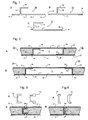
- Figures 1A to C illustrate edge profiles 1a to c which generally form the outward edge of a structural sandwich plate member such that, when a number of such plate members are formed into a large section or module, the outward edge of that module is largely comprised of edge profiles that can be mated and joined by welding the welding location on the outward edge of an adjacent module.
- the edge profiles include built-in backing bars and full or partial penetration groove weld preparations at the possible weld locations to eliminate the need of providing or making these in situ.
- These sections may be roll formed or fabricated from standard shapes and plates in steel. Alternatively they may be extruded in aluminium for applications where light weight is desired, e.g. the upper decks of cruise ships or for hull forms in fast ships.
- other metals may be used if desired and structural profiles of different metals may be used together to form structural sandwich plate members according to the invention.
- the edge profile 1a shown in Figure 1A which is a lateral cross-section, comprises a generally planar portion (long flange) 11 which will form part of one outer plate of a structural sandwich plate member and has sufficient length that the tip can be displaced (e.g. by up to ⁇ 5mm) to be aligned with the adjacent module.
- Placed inwardly from one edge of the section is an upstanding web 12 which will extend across the thickness of the structural sandwich plate member.
- a short flange 13 parallel to the long flange 11 and extending towards its centre is provided. Short flange 13 provides a landing surface for the metal plate used to complete the structural sandwich plate member.
- Full penetration groove weld preparations 14 are provided at the edges of the long flange 11 to enable an adjacent plate or edge profile to be welded to the edge profile from the exterior. As can be seen in the subsequent description, possible weld locations include the full penetration groove weld preparations 14 and the end of the short flange 13.
- Figure 1B illustrates an alternative edge profile 1b similar to that of Figure 1A and again comprising a plate portion (long flange) 11, upstanding web 12 and short flange 13.
- the weld preparations 14 of the long flange 11 enable an adjacent plate or like section to be welded to the edge profile 1b from the interior.
- Figure 1C illustrates a further alternative edge profile 1c which again consists of (long flange) plate portion 11, upstanding web 12 and short flange 13 performing the same functions as in the sections 1a, 1b of Figures 1A and B.
- edge profile 1c of Figure 1C the upstanding web 12 is located adjacent one side edge of the long flange 11.
- the edge weld preparation 14 on the other side may be arranged to enable welding from the exterior, as shown, or to enable welding from the interior, as desired for the intended fabrication sequence.
- a small projection 17 is provided, with its lower surface aligned with the inner surface of the long flange 11, to act as a backing bar to receive an adjacent plate.
- possible weld locations include the small projection 17, weld preparation 14 and the short flange 13.
- FIGS 2A and B illustrate two alternative ways in which profiles as shown in Figure 1C can be used to connect large sections or modules comprised of structural sandwich plate members.
- two sections or modules 2a, 2b are constructed of structural sandwich plate members comprising outer metal plates 21 bonded together by an elastomer core 22 which substantially contributes to the structural strength of the member.
- the edges of the sections 2a, 2b are closed by an edge profile 1c, one section 2a has the long flange 11 of the edge profile 1c downwards (as illustrated) and the other section 2b has the planar portion 11 upwards (as illustrated).
- the two sections 2a, 2b are fitted together with the free end of the long flange 11 of each edge profile 1c supported by the short flange 13 of the other edge profile 1c.
- Full penetration groove butt welds 4b are made to connect the adjacent modules together at the weld location.
- the newly-formed cavity 5 is then injected with elastomer to make the construction continuous. If necessary, the degree of overlap between the short flange 13 of one section and the long flange 11 of the other can be varied to accommodate normal variations in fit-up that are associated with making modules.
- edge profiles 1d are positioned with their long flanges 11 on the same side.
- the weld preparation as shown in Figure 2B allows the finishing butt weld 4b to be made at the weld location from the interior.
- plate 6, which preferably has the same thickness as the outer plates 21 of modules 2a, 2b, is welded 4b at the weld location to close cavity 5, with the short flanges 13 acting as landing surfaces and backing bars.
- Cavity 5 is then injected with elastomer to make the connecting plate segment composite. This method of connection between modules allows for greater variations in alignment than the method of Fig 2A .
- Figures 3A and B illustrate the deep male and female socket profiles and their use to align and join adjacent structural sandwich plate members.
- a male socket profile 71 and female socket profile 72 have complimentary U-shapes that mate, providing alignment and shear capacity between joining prefabricated structural sandwich plate members.
- the total depth of the webs of the male and female socket profiles 71, 72 are equal to the core thickness of the sandwich plate member in the edge of which they are fitted.
- the two structural sandwich plate members have the same thickness but the socket profiles may be varied to connect together structural sandwich plate members of different thicknesses or different metal plate thicknesses.
- the socket profiles may extend for some or preferably all of the entire lengths of the edges of the structural sandwich plate members and are welded to metal plates 21 by fillet welds 4a as illustrated in Figure 3B to form metal boxes with enclosed air-tight cavities.
- Other profiles may also be integrated into the cavities or used along the edges. These cavities are injected with elastomer 22 and after curing form structural sandwich plate members. Larger sections can be made by mating the male and female socket profiles 71, 72 along the edges of adjacent plate members at the weld locations, as shown in Figure 3B and making them continuous by welding butt welds (not shown).
- the deep socket profiles need not be fully butted, as shown in Figure 3B , but may have a gap between profiles to accommodate misalignment within the plane of the plate members.
- Figures 4A and B illustrate shallow male and female socket profiles 73, 74 which form one or more edges of a structural sandwich plate member and are used in the same manner as the deep socket profiles 71, 72.
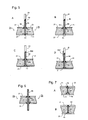
- Figures 5A to D illustrate various plate profiles that are integrated into structural sandwich plate members and that are used to connect structural sandwich plate members that are in general perpendicular to a metal web.
- Figure 5A illustrates the basic form of a plate profile 81.
- the lower part of the profile 81 is shaped like an I-beam with upper and lower flanges 811, 812.
- a web extends above the upper flanges.
- the flanges 811, 812 act as landing surfaces and backing bars to allow the outer metal plates 21 of structural sandwich plate members 2a, 2b to be welded to the plate profile 81 with butt or full penetration groove welds 4a.
- the web extending above the upper flanges 811 is used as a weld location to connect to the perpendicular metal web.
- elastomer 22 is injected into the cavities to form the structural sandwich plate members 2a, 2b.
- Conventional metal plates or webs 61 are welded to the plate profile 81 at the weld location with either full penetration groove welds or butt welds 4b that are located sufficiently away from the core as not to damage it by the welding process.
- Plate profiles 82 and 83 shown in Figure 5B and 5C respectively, are simplified and have one set of landing surfaces/backing bars for the interior one of plates 21.
- the profile is fillet welded to the exterior one of plates 21 and welded to the web 61 at the weld location with either a one-sided full penetration groove weld or with two-sided partial penetration groove welds.
- the plate profile 84 shown in Figure 5D is similar to profile 82 but has an additional backing bar alignment plate 842 to facilitate the welding of the web 61 at the weld location.
- Figure 6 illustrates a through-thickness profile 85 which can be used to transfer force directly through structural sandwich plate members.
- the through-thickness profile 85 comprises a plate of constant thickness from which project two spaced apart pairs of flanges 851, 852. These flanges 851, 852 act as landing surfaces and backing bars for plates 21 forming the outer plates of structural sandwich plate elements 2a, 2b which are welded to it. Webs or other conventional metal plates can be welded at weld locations to the through-thickness profile 85 of the precast structural sandwich panel during construction.
- Spacer profiles 91 and 93 can be used to act as a landing surface and backing bar 92 for making plate seams and to space apart plates 21 which form the outer plates of structural sandwich plate members.
- Spacer profiles 91 and 93 are I-shaped and T-shaped respectively. Each is first welded with fillet welds to the exterior plate and then to the interior plates at a weld location when the plate seam is welded.
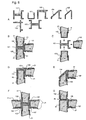
- FIG. 8A Various sandwich plate profiles 101 to 107 for joining mutually perpendicular structural sandwich plate members are shown in cross-section in Figures 8A , whilst their manner of use is shown in Figures 8B to 8D .
- These sandwich plate profiles may also be referred to as nodal profiles.
- FIG 8B three prefabricated sandwich plate members are connected together with two aligned and the third extending perpendicularly from them and is representative of a typical deck to side shell connection detail.
- the nodal profile 101 used to effect this connection is a roll-formed or extruded section of metal having sockets facing the directions of the structural sandwich plate members which are to be connected.
- the overall form is H-shaped with the third socket formed by flanges provided on one of the uprights of the H.
- a male socket profile 102 forming the edge of the prefabricated structural sandwich plate members is inserted into the nodal profile 101 and welded at weld locations to form a continuous structure as shown in Figure 8C . Finishing welds (not shown) make the joint continuous. Localised welding can be carried out without affecting the structural integrity of the joint.
- Figures 8D and 8E illustrate the method of use of two nodal profiles 103 and 104 that are used to connect two prefabricated structural sandwich plate members and are again representative of a typical deck side shell construction detail.
- Nodal profiles 103 and 104 provide a right angle connection with a square outer corner and a chamfered outer corner, respectively.
- the profiles are generally U-shaped with small perpendicular plate protrusions on the outside face of one leg which form the second socket.
- Figure 8F illustrates the method of use for sandwich plate profile 107 that would be used to connect four prefabricated structural sandwich plate members and is representative of a typical inner hull stool bulkhead connection.
- Figure 8G illustrates the method of use for the sandwich plate profile 106 which is integrated into one structural sandwich plate member and subsequently made continuous with two other precast structural sandwich plate members by welding at weld locations. Again, finishing welds are omitted for clarity.
- the nodal profile 106 is basically a structural angle with inner small plate protrusions which are perpendicular to the outside face of the legs of the angle. The small plates provide alignment, socket and weld details for accepting two precast structural sandwich plate members.
- Figures 9A to J Arrangements to connect angled structural sandwich plate members to each other and to conventional plates in which at least one plate member is framed into the joint at an oblique angle are shown in Figures 9A to J.
- the connections of Figures 9A to G a re representative of typical connection between a hopper, inner hull bottom and a longitudinal girder, or between the side shell, hopper-side shell and a stringer.
- Figures 9H , I and J can be used for hopper to inner hull bottom to stool connections.
- Figures 9A to E illustrate complex profiles that are integrated into the steel fabrication process prior to the injection of elastomer and their manner of use whilst Figures 9F and 9G illustrate complex profiles that join precast structural sandwich plate members.
- Figure 9A illustrates a basic form of a complex profile 110 which is used to connect an inclined structural sandwich plate member, a horizontal structural sandwich plate member and a vertical metal plate.
- the complex profile 110 essentially comprises a vertical plate portion which is to be aligned with and butt welded to a vertical metal plate at a weld location.
- Four flanges 111-114, extending from the vertical plate portion a distance sufficient to place joining welds to outer plates 61 in a lower stress range region (for better fatigue resistance) are spaced apart and oriented to align with the outer plates 21 of the inclined and horizontal structural sandwich plate members.
- the outer plates 21 of the structural sandwich plate members are butt welded to the respective tips of flanges 111-114.
- the extension of the vertical metal plate through the core depth of the structural sandwich plate members transmits the through-thickness forces associated with the vertical force component in the inclined structural sandwich plate member.
- Figures 9B, 9C and 9D are variations of the basic form of the complex profile which include different weld preparations.
- the flange tips of flanges 121-124 and 131-134 of complex profiles 120 and 130 in Figures 9B and 9C have been bevelled for full penetration groove welds to made form the outside or all from above, respectively.
- Complex profile 120 in Figure 9D has integrated backing bars 145 which provide the landing surface and alignment necessary to make butt welds between the outer plates 21 and the complex profile 140 from the preferred directions.
- Complex profile 150 in Figure 9E is a variant of complex profile 140 with solid core 151 having side faces 152, facing the structural sandwich plate members and rolled notches 153 that provide the same function as backing bars.
- Figures 9F and 9G illustrate two additional variations of the basic form of the complex profile in Figure 9A that would be used to join prefabricated structural sandwich plate members to conventional metal plates.
- Figure 9G illustrates the use of a solid metal block or bar 107 as an alternative male socket member to the U-shaped profile and the same solid core variation 171 as illustrated in Figure 9E .
- complex profiles may be provided that are integrated into one or more structural sandwich plate members and provided with one or more sockets for connection to one or more prefabricated structural sandwich plate members.
- Figures 9H , I and J illustrate a variety of complex profiles 180, 190, 200 for typical hopper to inner hull bottom to stool connections and their manner of use for joining prefabricated structural sandwich plate members and conventional metal plates.
- appropriately oriented and spaced flanges 181, 182, 191, 192, 201, 202 are provided to form sockets to receive male socket members 102, 105 provided in the ends of the structural sandwich plate members and webs 183, 193, 203 transmit through-thickness forces.
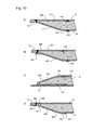
- Figures 10A to C illustrate transition profiles 210, 220, 230 which are used to connect a structural sandwich plate member to an aligned conventional metal plate or web.
- transition profile 210 essentially comprises two plate portions 211, 212 which are joined together at one edge, where they are to be welded to the conventional metal plate 73 at a weld location.
- the upper plate portion 211 is parallel and aligned with the conventional metal plate 73 where as the lower plate portion 212 is inclined so that at the distal edges of the plate portions 213, 214 they are spaced apart by a distance equal to the thickness of the structural sandwich plate member to which the outer plates 21 are welded.
- the distal end portion 213 of plate portion 212 is made parallel to the other plate portion 211 and the outer plate of the structural sandwich plate member to which it is to be connected.
- the distal end portions of the plate portions 211, 212 are also provided with backing bars 214 to assist in welding the outer plates 21 of the structural sandwich plate member to transition profile 210.
- Transition profile 220 shown in Figure 10B is a very similar to transition profile 210 of Figure 10 A but the upper link member 221 is shortened so that the points of connection between plate portions 221, 222 and the respective outer plates 21 of the structural sandwich plate member are not aligned vertically and in which an additional backing bar detail has been included to facilitate the welding of the transition profile to the metal plate 73 at the weld location.
- Transition profile 230 shown in Figure 10C is for use where the existing plate 74 extends to form one of the outer plate members of the structural sandwich plate member, as in the case of structural overlays.
- the lower plate portion 231 is placed against and welded at its edges to plate 74.
- the upper plate portion 232 is joined at one edge to one edge of lower plate portion 231 and rises up so as to be spaced from lower plate portion 231 for connection to plate 21 which forms the other outer plate of the structural sandwich plate member.
- Transitional profile 240 is shown in Figure 10D and is simpler to roll-form.
- Transitional profile 240 comprises a head portion 241, a main angled plate 242 and a tail portion 243.
- the head portion has a backing bar 244 and weld preparation 245 at a weld location for connection to an existing metal plate 73 as well as a shoulder 246 to receive one outer metal plate 21 of the structural sandwich plate element.
- the tail portion 243 has a backing bar 247 for receiving the other outer metal plate 21 whilst the main angled plate 242 makes the transition from the existing metal plate 73 to the full thickness of the structural sandwich plate member.
- FIG. 11 is a mid-tank cross section of the tanker 300 with the left hand part showing longitudinal framing and the right hand part showing a typical transverse frame.
- Figure 12 is a longitudinal section for a portion of tank section along a longitudinal frame.
- Figure 13 is an isometric exploded view of a typical tank section.
- Figure 14 is a partially exploded view with enlarged portions showing the use of profiles according to the invention to connect a structural sandwich plate member, e.g.
- FIG. 15 is a perspective view of two hull sections with an enlarged portion showing the use of edge profiles according to the invention to join the modules.
- the deck plate 311, outer hull 302, 303, 310, 314 and inner hull 304, 305, 316, 317 would be constructed with structural sandwich plate members.
- the corrugated bulkhead 315, longitudinal framing 306, 307, 312 and transverse framing 308, 309, 313 would be constructed with metal plates.
- Profiles according to the present invention, described above and illustrated in Figures 1 to 10 would be used to join these members. All members are made continuous by welding and according to the present invention a significant number of structural sandwich plate elements may be prefabricated and subsequently welded together at a weld location on site.
- the plate profiles 81, 82, 83, 84 shown in Figures 5A to D can be used to connect a longitudinal or transverse framing plate 306, 307, 308, 309, 312, 313 to a structural sandwich plate member 2d forming part of the inner or outer hulls 302, 303, 304, 305, 310, 314, 316, 317.
- An example of connection of a longitudinal framing plate is shown in greater detail in Figure 14 .
- the structural sandwich plate member 2d is made up from three elongate steel plates 21 a, 21b, 21c of which the largest 21a forms the outermost layer of the outer hull or the innermost layer of the inner hull.
- Edge profiles 1a, 1b, or 1c are welded along the short edges of the plate 21a, these edges will form the edge of a hull section in which the structural sandwich plate member 2d is to be incorporated and facilitate connection of hull sections as described above.
- socket profiles 71, 72 are welded to facilitate connection of the structural sandwich plate member 2d to adjacent members in the hull section.
- the plate profile 81, 82, 83 or 84 is welded along the centre line of plate 21a. Plates 21b and 21c can then be welded in place with the edge profiles 1a, 1b, 1c, or 1d, socket profiles 71, 72 and backing bars on the plate profile 81, 82, 83 or 84 supporting the plates 21b, 21c.
- the framing plate 306, 307 can then be welded to the plate profile 81 at the welding location which projects far enough from the structural sandwich plate member 2d to prevent the heat of welding damaging the elastomer. It will be appreciated that the construction of the structural sandwich plate member 2d and optionally also the connection of the longitudinal framing plate 306, 307 can be carried out in a factory rather than a shipyard, enabling improved dimensional accuracy and higher quality construction through well cured elastomer and good welds.
- edge profiles according to the invention can be employed to facilitate connection of hull sections or modules of other structures, allowing the modules or sections to be constructed off-site for convenience and improved dimensional accuracy.
- Figure 15 shows the connection of two hull modules 401, 402 of the vessel 300.
- the modules 401, 402 are constructed so that the edges of the structural sandwich plate members which form the edges of the sections are provided with edge profiles 1c.
- the free edges of the long flanges 11 of the edge profiles 1c can be displaced as necessary to line up against the end of the short flange of the edge profile 1c on the other section.
Claims (24)
- Struktursandwichplattenbauteil enthaltend eine erste und eine zweite äußere Metallplatte; einen Elastomer-Kern, der die äußeren Metallplatten mit einer ausreichenden Stärke kontaktiert, um Scherkräfte zwischen ihnen zu übertragen; gekennzeichnet durch ein Verbindungsbauteil, das ein Randbauteil ist, das gebildet ist durch ein gewalztes oder extrudiertes Profil und zwischen die erste und zweite äußere Metallplatte eingepasst und mit diesen verbunden ist, wobei das Verbindungsbauteil sich entlang mindestens eines Teils der Peripherie der äußeren Metallplatten erstreckt, und das Profil eine Schweißstelle bereitstellt, die geeignet ist zum Schweißen des Struktursandwichplattenbauteils an ein anderes Struktursandwichplattenbauteil.
- Struktursandwichplattenbauteil nach Anspruch 1, bei dem das Verbindungsbauteil einen Steg enthält, der an die erste äußere Platte anstößt und durch die zweite äußere Platte hindurch vorsteht.
- Struktursandwichplattenbauteil nach Anspruch 1, bei dem das Verbindungsbauteil einen Steg enthält, der durch beide, die erste und zweite Metallplatte hindurch vorsteht.
- Struktursandwichplattenbauteil nach Anspruch 1 oder 2, bei dem das Verbindungsbauteil ferner mindestens einen Flansch enthält, der von dem Steg vorsteht, um als Stützstab zu wirken zum Schweißen von einer der äußeren Platten an den Steg.
- Struktursandwichplattenbauteil nach Anspruch 1, 2 oder 3, bei dem der oder ein Rand des Stegs, der durch eine der äußeren Metallplatten hindurch vorsteht, Ansätze aufweist zum Stoßschweißen an eine koplanare Platte.
- Struktursandwichplattenbauteil nach Anspruch 1, bei dem das Verbindungsbauteil einen I-Balken oder einen T-Balken enthält, der sich senkrecht zu und zwischen der ersten und zweiten Metallplatte erstreckt.
- Struktursandwichplattenbauteil nach Anspruch 1, bei dem das Randbauteil einen ersten Flansch enthält, der im Wesentlichen koplanar zu der ersten äußeren Metallplatte ist, einen Steg, der von dem ersten Flansch nach oben weist, und einen zweiten Flansch, der sich von dem Ende des Stegs parallel zu dem ersten Flansch erstreckt und mindestens teilweise gegen die zweite äußere Platte aufliegt.
- Struktursandwichplattenbauteil nach Anspruch 7, bei dem der Steg von einem Rand des ersten Flansches nach oben weist.
- Struktursandwichplattenbauteil nach Anspruch 8, bei dem das Randbauteil ferner einen dritten Flansch enthält, der im Wesentlichen parallel zu dem ersten Flansch ist und von dem Steg in der entgegengesetzten Richtung zu dem ersten Flansch vorsteht, wobei der dritte Flansch positioniert ist, um als Stützstab zu wirken zum Schweißen der ersten äußeren Platte an das Randbauteil.
- Struktursandwichplattenbauteil nach einem der Ansprüche 7 bis 9, bei dem mindestens ein Rand des ersten Flansches bereitgestellt ist mit Ansätzen zum Stoßschweißen an einen anderen Flansch oder eine Platte.
- Struktursandwichplattenbauteil nach einem der Ansprüche 7 bis 10, bei dem der zweite Flansch sich jenseits des Randes der zweiten äußeren Platte erstreckt, um als Abstützung zu wirken zum Schweißen einer anderen Platte oder eines Flansches an das Struktursandwichplattenbauteil.
- Struktursandwichplattenbauteil nach Anspruch 7, bei dem das Randbauteil im Querschnitt U-förmig ist mit einem Basisbereich und zwei Armen, wobei die Arme des U im Wesentlichen parallel zu der ersten und zweiten äußeren Platte sind und mindestens teilweise gegen die erste und zweite äußere Platte aufliegen.
- Struktursandwichplattenbauteil nach Anspruch 12, bei dem der Basisbereich des Randbauteils von den Rändern der ersten und zweiten äußeren Platte nach außen vorsteht, um in eine Fassung eingreifbar zu sein.
- Struktursandwichplattenbauteil nach Anspruch 12, bei dem der Basisbereich des Randbauteils von den Rändern der ersten und zweiten äußeren Platte nach innen beabstandet ist, um eine Fassung zu bilden.
- Struktursandwichplattenbauteil nach Anspruch 1, bei dem das Randbauteil einen schrägen Flansch enthält, der einen spitzen Winkel mit der ersten äußeren Metallplatte bildet und an einem ersten und zweiten Rand mit der ersten bzw. zweiten äußeren Metallplatte verbunden ist.
- Struktursandwichplattenbauteil nach Anspruch 15, bei dem das Randbauteil ferner einen Kopfbereich enthält, der mit dem ersten Rand des schrägen Flansches verbunden ist, wobei der Kopfbereich Schweißansätze aufweist zum Stoßschweißen an eine andere Platte oder einen Flansch, die/der zu der ersten äußeren Metallplatte ausgerichtet ist.
- Struktursandwichplattenbauteil nach Anspruch 16, bei dem der schräge Flansch über den Kopfbereich mit dem ersten Flansch verbunden ist.
- Struktursandwichplattenbauteil nach Anspruch 17, bei dem das Randbauteil ferner einen weiteren Flansch enthält, der im Wesentlichen parallel zu der ersten äußeren Platte und an einem ersten Rand mit dem Kopfbereich verbunden ist.
- Struktursandwichplattenbauteil nach Anspruch 18, bei dem der weitere Flansch an seinem zweiten Rand an die erste äußere Platte stoßgeschweißt ist, sodass der geneigte Flansch mit der ersten äußeren Platte über den Kopfbereich und den weiteren Flansch verbunden ist.
- Struktursandwichplattenbauteil nach Anspruch 18, bei dem der weitere Flansch die erste äußere Platte überlagert.
- Struktursandwichplattenbauteil nach Anspruch 20, bei dem die erste äußere Platte eine existierende Metallplatte einer Struktur ist, an die das Struktursandwichplattenbauteil ergänzt wird.
- Struktursandwichplattenbauteil nach einem der Ansprüche 15 bis 21, bei dem der schräge Flansch an seinem zweiten Rand einen Endbereich hat, der im Wesentlichen parallel zu der zweiten äußeren Platte ist.
- Strukturteil enthaltend mindestens ein erstes und zweites Struktursandwichplattenbauteil nach Anspruch 1, wobei das erste und zweite Struktursandwichplattenbauteil durch das Verbindungsbauteil von entweder dem ersten oder zweiten Struktursandwichplattenbauteil verbunden sind, wobei das Verbindungsbauteil gebildet ist durch ein gewalztes oder extrudiertes Längsprofil.
- Strukturteil enthaltend mindestens ein erstes und zweites Struktursandwichplattenbauteil nach Anspruch 1, wobei das erste und zweite Struktursandwichplattenbauteil durch ein Knotenprofil verbunden sind, das von den Verbindungsbauteilen des ersten und zweiten Struktursandwichplattenbauteils verschieden ist, wobei das Knotenprofil durch ein gewalztes oder extrudiertes Längsprofil gebildet ist.
Applications Claiming Priority (3)
| Application Number | Priority Date | Filing Date | Title |
|---|---|---|---|
| GB0104846A GB2372476A (en) | 2001-02-27 | 2001-02-27 | Structural sandwich plate members |
| GB0104846 | 2001-02-27 | ||
| PCT/GB2002/000157 WO2002068186A1 (en) | 2001-02-27 | 2002-01-15 | Improved structural sandwich plate members |
Publications (2)
| Publication Number | Publication Date |
|---|---|
| EP1365911A1 EP1365911A1 (de) | 2003-12-03 |
| EP1365911B1 true EP1365911B1 (de) | 2013-09-11 |
Family
ID=9909626
Family Applications (1)
| Application Number | Title | Priority Date | Filing Date |
|---|---|---|---|
| EP02744907.3A Expired - Lifetime EP1365911B1 (de) | 2001-02-27 | 2002-01-15 | Verbesserte sandwichplattenglieder |
Country Status (9)
| Country | Link |
|---|---|
| US (1) | US7877960B2 (de) |
| EP (1) | EP1365911B1 (de) |
| JP (1) | JP4712280B2 (de) |
| KR (1) | KR100878063B1 (de) |
| CN (1) | CN1292897C (de) |
| CA (1) | CA2439353A1 (de) |
| ES (1) | ES2433275T3 (de) |
| GB (1) | GB2372476A (de) |
| WO (1) | WO2002068186A1 (de) |
Cited By (1)
| Publication number | Priority date | Publication date | Assignee | Title |
|---|---|---|---|---|
| US20120040135A1 (en) * | 2008-12-04 | 2012-02-16 | Jon Micheal Werthen | Sandwich Panel, Support Member for Use in a Sandwich Panel and Aircraft Provided with Such a Sandwich Panel |
Families Citing this family (32)
| Publication number | Priority date | Publication date | Assignee | Title |
|---|---|---|---|---|
| GB2368041B (en) * | 2000-10-17 | 2004-04-21 | Intelligent Engineering | Sandwich plate stepped risers |
| NL1022237C2 (nl) * | 2002-12-20 | 2004-07-01 | Stork Fokker Aesp Bv | Laminaat met stompgelaste metaallagen. |
| GB2399540B (en) * | 2003-03-18 | 2005-10-26 | Intelligent Engineering | Improved method for reinforcing or reinstating existing structures |
| GB2399539B (en) * | 2003-03-18 | 2005-09-07 | Intelligent Engineering | Method for connecting structural sandwich plate members |
| DE10350953A1 (de) * | 2003-10-30 | 2005-06-16 | Alcan Technology & Management Ag | Verbindung von Verbundwerkstoffen |
| GB2414213B (en) * | 2004-05-21 | 2008-11-12 | Intelligent Engineering | Improved structural sandwich plate members |
| TWI360599B (en) | 2007-01-04 | 2012-03-21 | Nippon Steel Corp | Floor structure |
| GB2445740A (en) * | 2007-01-18 | 2008-07-23 | Intelligent Engineering | Flooring panels |
| EP2225424B1 (de) * | 2007-11-13 | 2018-01-10 | Casata Technologies Inc. | Metalischer Träger für einen Bodenaufbau |
| GB2465568A (en) * | 2008-11-19 | 2010-05-26 | Intelligent Engineering | A prefabricated floor panel |
| GB2475088A (en) * | 2009-11-05 | 2011-05-11 | Intelligent Engineering | Sandwich panels, and vessel or structure made by combining these using closing plates |
| DE202010014620U1 (de) * | 2010-10-22 | 2011-02-10 | Kraussmaffei Technologies Gmbh | Sandwichpaneel |
| FR2970900B1 (fr) * | 2011-01-31 | 2013-10-18 | Aircelle Sa | Procede de reparation d'un panneau d'attenuation acoustique |
| EP2538167A1 (de) * | 2011-06-23 | 2012-12-26 | Nederlandse Organisatie voor toegepast -natuurwetenschappelijk onderzoek TNO | Explosions- und bruchsichere Wandabschnitte zur Verwendung in Strukturen wie Schiffen |
| KR20130010243A (ko) * | 2011-07-18 | 2013-01-28 | 대우조선해양 주식회사 | 구조 샌드위치 플레이트의 연결구조 |
| KR101326493B1 (ko) * | 2011-11-23 | 2013-11-08 | 현대자동차주식회사 | 탄소섬유 고분자 복합재와 금속재를 결합시키기 위한 장치 및 방법 |
| US8973337B2 (en) * | 2012-08-20 | 2015-03-10 | William Hires | Modular sheet metal building kit |
| US20150135617A1 (en) * | 2013-11-18 | 2015-05-21 | HUNG Ming LIU | Fast installation/removal building partition structure |
| US9611646B2 (en) * | 2014-10-31 | 2017-04-04 | Rapid Fabrications Ip, Llc | Connection mechanisms for structural members and related assemblies and methods |
| CN109689265A (zh) * | 2016-04-27 | 2019-04-26 | 蒂森克虏伯钢铁欧洲股份公司 | 多层部件及其制造方法 |
| DE102016012691A1 (de) * | 2016-10-25 | 2018-04-26 | Hydro Aluminium Rolled Products Gmbh | Mehrschichtiges Strukturbauteil, Verfahren zu dessen Herstellung und Verwendungen dafür |
| ES2758104T3 (es) * | 2017-02-28 | 2020-05-04 | Oy Fcr Finland Ltd | Un elemento enmarcado y su uso |
| US11148722B2 (en) * | 2017-06-02 | 2021-10-19 | Norco Industries, Inc. | Ultra light trailer frame |
| JP6819479B2 (ja) * | 2017-06-21 | 2021-01-27 | トヨタ自動車株式会社 | 金属部材及びその製造方法 |
| EP3683132A4 (de) * | 2017-09-12 | 2021-06-30 | Tae Young Chung | Wärmedämmendes baumaterial und niedertemperatur- sowie ultraniedertemperatur-flüssiggasträger damit |
| CN108277923B (zh) * | 2018-03-27 | 2023-09-12 | 长春工程学院 | 新型组合式保温复合墙板 |
| JP6681941B2 (ja) | 2018-05-31 | 2020-04-15 | 株式会社Uacj | 衝撃吸収部材 |
| CN109823468B (zh) * | 2018-08-29 | 2023-09-08 | 江苏科技大学 | 一种船用t形分布夹层板连接组件及安装方法 |
| WO2020167671A2 (en) * | 2019-02-14 | 2020-08-20 | 500 Group, Inc. | Foldable building structures with utility channels and laminate enclosures |
| CN109878541B (zh) | 2019-03-01 | 2020-06-05 | 中车青岛四方机车车辆股份有限公司 | 一种轨道车辆、司机室及复合铝板组件 |
| FI129690B (en) * | 2020-03-31 | 2022-06-30 | Shipmypacket Oy | Automated warehouse system and components and methods to make this |
| CN114932974A (zh) * | 2022-06-24 | 2022-08-23 | 广船国际有限公司 | 一种船舶外板及船舶 |
Citations (1)
| Publication number | Priority date | Publication date | Assignee | Title |
|---|---|---|---|---|
| GB2337022A (en) * | 1998-05-08 | 1999-11-10 | Fern Investments Ltd | Composite structural laminate |
Family Cites Families (22)
| Publication number | Priority date | Publication date | Assignee | Title |
|---|---|---|---|---|
| US3357146A (en) * | 1964-02-19 | 1967-12-12 | Birdsboro Corp | Building panel splicing |
| US3535844A (en) * | 1969-10-30 | 1970-10-27 | Glaros Products Inc | Structural panels |
| US3810337A (en) * | 1970-10-28 | 1974-05-14 | S Pollard | An elongated stressed structural member |
| GB1451111A (en) * | 1973-12-11 | 1976-09-29 | Hemmings Co Ltd C | Thermal insulating panels for cold-stores cold rooms refriger ated chambers and the like |
| US4518026A (en) * | 1980-07-14 | 1985-05-21 | Garland Manufacturing Co. | Energy efficient garage door construction and the like |
| JPS61158435A (ja) * | 1984-12-28 | 1986-07-18 | いすゞ自動車株式会社 | 中空体内部に芯材を通した複合積層体及びその製造法 |
| JPS63135605A (ja) * | 1986-11-28 | 1988-06-08 | 日本電信電話株式会社 | サンドイツチ板接合部構造 |
| GB8918594D0 (en) | 1989-08-15 | 1989-09-27 | Presco Int | Portable buildings |
| GB2244237A (en) * | 1990-02-23 | 1991-11-27 | Hunter Douglas Ind Bv | Bullet-proof wall panel |
| DE4012206C2 (de) * | 1990-04-14 | 1994-02-17 | Porsche Ag | Verbundelement |
| AU668735B2 (en) * | 1992-12-28 | 1996-05-16 | Ig-Technical Research Inc. | Refractory heat-insulating panel |
| US5373678A (en) * | 1994-02-22 | 1994-12-20 | Hesser; Francis J. | Structural panel system |
| CN2282977Y (zh) * | 1995-04-22 | 1998-06-03 | 林祺炳 | 一种板材 |
| ATE202046T1 (de) * | 1995-08-25 | 2001-06-15 | Alusuisse Airex Ag | Profile für plattenförmige verbundelemente |
| CH690759A5 (de) * | 1996-10-09 | 2001-01-15 | Alusuisse Tech & Man Ag | Mehrschichtige Verbundplatte. |
| US5778813A (en) * | 1996-11-13 | 1998-07-14 | Fern Investments Limited | Composite steel structural plastic sandwich plate systems |
| GB2355957B (en) * | 1999-11-05 | 2003-07-02 | Intelligent Engineering | Composite structural laminate plate construction |
| US6050208A (en) * | 1996-11-13 | 2000-04-18 | Fern Investments Limited | Composite structural laminate |
| US6418686B1 (en) * | 1997-04-25 | 2002-07-16 | Leading Edge Earth Products, Inc. | Insulated asymmetrical directional force resistant building panel with symmetrical joinery, integral shear resistance connector and thermal break |
| US6276748B1 (en) * | 1998-03-17 | 2001-08-21 | Western Sear Trucks Inc. | Lightweight cab/sleeper for trucks |
| US6311454B1 (en) * | 1999-02-18 | 2001-11-06 | Globe Door, L.L.C. | Door construction |
| GB0216699D0 (en) * | 2002-07-18 | 2002-08-28 | Holloway Wynn P | A building panel |
-
2001
- 2001-02-27 GB GB0104846A patent/GB2372476A/en not_active Withdrawn
-
2002
- 2002-01-15 ES ES02744907T patent/ES2433275T3/es not_active Expired - Lifetime
- 2002-01-15 WO PCT/GB2002/000157 patent/WO2002068186A1/en active Application Filing
- 2002-01-15 JP JP2002567527A patent/JP4712280B2/ja not_active Expired - Lifetime
- 2002-01-15 US US10/470,938 patent/US7877960B2/en not_active Expired - Fee Related
- 2002-01-15 CA CA 2439353 patent/CA2439353A1/en not_active Abandoned
- 2002-01-15 KR KR1020037011263A patent/KR100878063B1/ko active IP Right Grant
- 2002-01-15 CN CNB028055020A patent/CN1292897C/zh not_active Expired - Fee Related
- 2002-01-15 EP EP02744907.3A patent/EP1365911B1/de not_active Expired - Lifetime
Patent Citations (1)
| Publication number | Priority date | Publication date | Assignee | Title |
|---|---|---|---|---|
| GB2337022A (en) * | 1998-05-08 | 1999-11-10 | Fern Investments Ltd | Composite structural laminate |
Cited By (1)
| Publication number | Priority date | Publication date | Assignee | Title |
|---|---|---|---|---|
| US20120040135A1 (en) * | 2008-12-04 | 2012-02-16 | Jon Micheal Werthen | Sandwich Panel, Support Member for Use in a Sandwich Panel and Aircraft Provided with Such a Sandwich Panel |
Also Published As
| Publication number | Publication date |
|---|---|
| ES2433275T3 (es) | 2013-12-10 |
| GB0104846D0 (en) | 2001-04-18 |
| KR20030081470A (ko) | 2003-10-17 |
| US20040067373A1 (en) | 2004-04-08 |
| WO2002068186A1 (en) | 2002-09-06 |
| EP1365911A1 (de) | 2003-12-03 |
| CN1492805A (zh) | 2004-04-28 |
| CN1292897C (zh) | 2007-01-03 |
| GB2372476A (en) | 2002-08-28 |
| CA2439353A1 (en) | 2002-09-06 |
| US7877960B2 (en) | 2011-02-01 |
| JP4712280B2 (ja) | 2011-06-29 |
| JP2004528196A (ja) | 2004-09-16 |
| KR100878063B1 (ko) | 2009-01-13 |
Similar Documents
| Publication | Publication Date | Title |
|---|---|---|
| EP1365911B1 (de) | Verbesserte sandwichplattenglieder | |
| EP2126454B1 (de) | Tankstruktur | |
| JP4335006B2 (ja) | 構造サンドイッチ板部材および連結部材を含む構造体ならびに該構造体の部品を製造する方法 | |
| EP1603703B1 (de) | Verfahren zur schweissverbindung von konstruktionssandwichplattengliedern mit kanalförmigen verbindungsgliedern | |
| WO2011020999A2 (en) | Improved hatchcover | |
| EP1573141B1 (de) | Grosse verbundkonstruktionen und verfahren zur herstellung grosser verbundkonstruktionen | |
| US7337736B2 (en) | Double hulls | |
| JP2740729B2 (ja) | 船体二重殻建造法 | |
| GB2475088A (en) | Sandwich panels, and vessel or structure made by combining these using closing plates | |
| CN113202209B (zh) | 面向核电站的装配式可调节多腔斜钢板剪力墙及其施工方法 | |
| EP1266821A2 (de) | Verfahren zum Bauen einer Struktur | |
| CN213359003U (zh) | 双皮墙连接构件及连接结构 | |
| WO2016062924A1 (en) | Boat hull, boat and use | |
| US20030024455A1 (en) | Movable bulkhead | |
| WO2009131547A1 (en) | Composite panel assemblies including separation prevention shear connectors | |
| JPH08218320A (ja) | 柱脚構造体の構築方法および鋼製エレメント |
Legal Events
| Date | Code | Title | Description |
|---|---|---|---|
| PUAI | Public reference made under article 153(3) epc to a published international application that has entered the european phase |
Free format text: ORIGINAL CODE: 0009012 |
|
| 17P | Request for examination filed |
Effective date: 20030729 |
|
| AK | Designated contracting states |
Kind code of ref document: A1 Designated state(s): AT BE CH CY DE DK ES FI FR GB GR IE IT LI LU MC NL PT SE TR |
|
| AX | Request for extension of the european patent |
Extension state: AL LT LV MK RO SI |
|
| 17Q | First examination report despatched |
Effective date: 20040702 |
|
| 17Q | First examination report despatched |
Effective date: 20040702 |
|
| GRAP | Despatch of communication of intention to grant a patent |
Free format text: ORIGINAL CODE: EPIDOSNIGR1 |
|
| GRAS | Grant fee paid |
Free format text: ORIGINAL CODE: EPIDOSNIGR3 |
|
| GRAA | (expected) grant |
Free format text: ORIGINAL CODE: 0009210 |
|
| AK | Designated contracting states |
Kind code of ref document: B1 Designated state(s): AT BE CH CY DE DK ES FI FR GB GR IE IT LI LU MC NL PT SE TR |
|
| REG | Reference to a national code |
Ref country code: GB Ref legal event code: FG4D |
|
| REG | Reference to a national code |
Ref country code: CH Ref legal event code: EP |
|
| REG | Reference to a national code |
Ref country code: AT Ref legal event code: REF Ref document number: 631371 Country of ref document: AT Kind code of ref document: T Effective date: 20130915 |
|
| REG | Reference to a national code |
Ref country code: IE Ref legal event code: FG4D |
|
| REG | Reference to a national code |
Ref country code: DE Ref legal event code: R096 Ref document number: 60245513 Country of ref document: DE Effective date: 20131031 |
|
| REG | Reference to a national code |
Ref country code: ES Ref legal event code: FG2A Ref document number: 2433275 Country of ref document: ES Kind code of ref document: T3 Effective date: 20131210 |
|
| REG | Reference to a national code |
Ref country code: NL Ref legal event code: T3 |
|
| PG25 | Lapsed in a contracting state [announced via postgrant information from national office to epo] |
Ref country code: CY Free format text: LAPSE BECAUSE OF FAILURE TO SUBMIT A TRANSLATION OF THE DESCRIPTION OR TO PAY THE FEE WITHIN THE PRESCRIBED TIME-LIMIT Effective date: 20130619 Ref country code: SE Free format text: LAPSE BECAUSE OF FAILURE TO SUBMIT A TRANSLATION OF THE DESCRIPTION OR TO PAY THE FEE WITHIN THE PRESCRIBED TIME-LIMIT Effective date: 20130911 |
|
| REG | Reference to a national code |
Ref country code: AT Ref legal event code: MK05 Ref document number: 631371 Country of ref document: AT Kind code of ref document: T Effective date: 20130911 |
|
| PG25 | Lapsed in a contracting state [announced via postgrant information from national office to epo] |
Ref country code: FI Free format text: LAPSE BECAUSE OF FAILURE TO SUBMIT A TRANSLATION OF THE DESCRIPTION OR TO PAY THE FEE WITHIN THE PRESCRIBED TIME-LIMIT Effective date: 20130911 Ref country code: GR Free format text: LAPSE BECAUSE OF FAILURE TO SUBMIT A TRANSLATION OF THE DESCRIPTION OR TO PAY THE FEE WITHIN THE PRESCRIBED TIME-LIMIT Effective date: 20131212 |
|
| PG25 | Lapsed in a contracting state [announced via postgrant information from national office to epo] |
Ref country code: CY Free format text: LAPSE BECAUSE OF FAILURE TO SUBMIT A TRANSLATION OF THE DESCRIPTION OR TO PAY THE FEE WITHIN THE PRESCRIBED TIME-LIMIT Effective date: 20130911 Ref country code: BE Free format text: LAPSE BECAUSE OF FAILURE TO SUBMIT A TRANSLATION OF THE DESCRIPTION OR TO PAY THE FEE WITHIN THE PRESCRIBED TIME-LIMIT Effective date: 20130911 |
|
| PG25 | Lapsed in a contracting state [announced via postgrant information from national office to epo] |
Ref country code: AT Free format text: LAPSE BECAUSE OF FAILURE TO SUBMIT A TRANSLATION OF THE DESCRIPTION OR TO PAY THE FEE WITHIN THE PRESCRIBED TIME-LIMIT Effective date: 20130911 |
|
| REG | Reference to a national code |
Ref country code: DE Ref legal event code: R097 Ref document number: 60245513 Country of ref document: DE |
|
| PG25 | Lapsed in a contracting state [announced via postgrant information from national office to epo] |
Ref country code: PT Free format text: LAPSE BECAUSE OF FAILURE TO SUBMIT A TRANSLATION OF THE DESCRIPTION OR TO PAY THE FEE WITHIN THE PRESCRIBED TIME-LIMIT Effective date: 20140113 |
|
| PLBE | No opposition filed within time limit |
Free format text: ORIGINAL CODE: 0009261 |
|
| STAA | Information on the status of an ep patent application or granted ep patent |
Free format text: STATUS: NO OPPOSITION FILED WITHIN TIME LIMIT |
|
| 26N | No opposition filed |
Effective date: 20140612 |
|
| PG25 | Lapsed in a contracting state [announced via postgrant information from national office to epo] |
Ref country code: MC Free format text: LAPSE BECAUSE OF FAILURE TO SUBMIT A TRANSLATION OF THE DESCRIPTION OR TO PAY THE FEE WITHIN THE PRESCRIBED TIME-LIMIT Effective date: 20130911 Ref country code: LU Free format text: LAPSE BECAUSE OF FAILURE TO SUBMIT A TRANSLATION OF THE DESCRIPTION OR TO PAY THE FEE WITHIN THE PRESCRIBED TIME-LIMIT Effective date: 20140115 |
|
| REG | Reference to a national code |
Ref country code: CH Ref legal event code: PL |
|
| REG | Reference to a national code |
Ref country code: DE Ref legal event code: R097 Ref document number: 60245513 Country of ref document: DE Effective date: 20140612 |
|
| PG25 | Lapsed in a contracting state [announced via postgrant information from national office to epo] |
Ref country code: DK Free format text: LAPSE BECAUSE OF FAILURE TO SUBMIT A TRANSLATION OF THE DESCRIPTION OR TO PAY THE FEE WITHIN THE PRESCRIBED TIME-LIMIT Effective date: 20130911 |
|
| PG25 | Lapsed in a contracting state [announced via postgrant information from national office to epo] |
Ref country code: LI Free format text: LAPSE BECAUSE OF NON-PAYMENT OF DUE FEES Effective date: 20140131 Ref country code: CH Free format text: LAPSE BECAUSE OF NON-PAYMENT OF DUE FEES Effective date: 20140131 |
|
| REG | Reference to a national code |
Ref country code: IE Ref legal event code: MM4A Ref country code: GB Ref legal event code: 732E Free format text: REGISTERED BETWEEN 20141009 AND 20141015 |
|
| PG25 | Lapsed in a contracting state [announced via postgrant information from national office to epo] |
Ref country code: IE Free format text: LAPSE BECAUSE OF NON-PAYMENT OF DUE FEES Effective date: 20140115 |
|
| REG | Reference to a national code |
Ref country code: FR Ref legal event code: PLFP Year of fee payment: 15 |
|
| PG25 | Lapsed in a contracting state [announced via postgrant information from national office to epo] |
Ref country code: TR Free format text: LAPSE BECAUSE OF FAILURE TO SUBMIT A TRANSLATION OF THE DESCRIPTION OR TO PAY THE FEE WITHIN THE PRESCRIBED TIME-LIMIT Effective date: 20130911 |
|
| REG | Reference to a national code |
Ref country code: FR Ref legal event code: PLFP Year of fee payment: 16 |
|
| REG | Reference to a national code |
Ref country code: FR Ref legal event code: PLFP Year of fee payment: 17 |
|
| REG | Reference to a national code |
Ref country code: GB Ref legal event code: 732E Free format text: REGISTERED BETWEEN 20190808 AND 20190814 |
|
| PGFP | Annual fee paid to national office [announced via postgrant information from national office to epo] |
Ref country code: DE Payment date: 20190731 Year of fee payment: 18 Ref country code: IT Payment date: 20190730 Year of fee payment: 18 |
|
| PGFP | Annual fee paid to national office [announced via postgrant information from national office to epo] |
Ref country code: ES Payment date: 20191030 Year of fee payment: 18 Ref country code: FR Payment date: 20191230 Year of fee payment: 19 |
|
| PGFP | Annual fee paid to national office [announced via postgrant information from national office to epo] |
Ref country code: NL Payment date: 20200130 Year of fee payment: 19 Ref country code: GB Payment date: 20200113 Year of fee payment: 19 |
|
| REG | Reference to a national code |
Ref country code: DE Ref legal event code: R119 Ref document number: 60245513 Country of ref document: DE |
|
| PG25 | Lapsed in a contracting state [announced via postgrant information from national office to epo] |
Ref country code: DE Free format text: LAPSE BECAUSE OF NON-PAYMENT OF DUE FEES Effective date: 20200801 |
|
| PG25 | Lapsed in a contracting state [announced via postgrant information from national office to epo] |
Ref country code: IT Free format text: LAPSE BECAUSE OF NON-PAYMENT OF DUE FEES Effective date: 20200115 |
|
| REG | Reference to a national code |
Ref country code: ES Ref legal event code: FD2A Effective date: 20210603 |
|
| REG | Reference to a national code |
Ref country code: GB Ref legal event code: 732E Free format text: REGISTERED BETWEEN 20210610 AND 20210616 |
|
| PG25 | Lapsed in a contracting state [announced via postgrant information from national office to epo] |
Ref country code: ES Free format text: LAPSE BECAUSE OF NON-PAYMENT OF DUE FEES Effective date: 20200116 |
|
| REG | Reference to a national code |
Ref country code: NL Ref legal event code: MM Effective date: 20210201 |
|
| GBPC | Gb: european patent ceased through non-payment of renewal fee |
Effective date: 20210115 |
|
| PG25 | Lapsed in a contracting state [announced via postgrant information from national office to epo] |
Ref country code: FR Free format text: LAPSE BECAUSE OF NON-PAYMENT OF DUE FEES Effective date: 20210131 Ref country code: NL Free format text: LAPSE BECAUSE OF NON-PAYMENT OF DUE FEES Effective date: 20210201 |
|
| PG25 | Lapsed in a contracting state [announced via postgrant information from national office to epo] |
Ref country code: GB Free format text: LAPSE BECAUSE OF NON-PAYMENT OF DUE FEES Effective date: 20210115 |