EP1365233A2 - Gasensor, Gassensorinbauvorrichtung und Verfahren zum Einbau von Gassensoren - Google Patents
Gasensor, Gassensorinbauvorrichtung und Verfahren zum Einbau von Gassensoren Download PDFInfo
- Publication number
- EP1365233A2 EP1365233A2 EP03251971A EP03251971A EP1365233A2 EP 1365233 A2 EP1365233 A2 EP 1365233A2 EP 03251971 A EP03251971 A EP 03251971A EP 03251971 A EP03251971 A EP 03251971A EP 1365233 A2 EP1365233 A2 EP 1365233A2
- Authority
- EP
- European Patent Office
- Prior art keywords
- section
- sealing surface
- coefficient
- housing
- thermal expansion
- Prior art date
- Legal status (The legal status is an assumption and is not a legal conclusion. Google has not performed a legal analysis and makes no representation as to the accuracy of the status listed.)
- Granted
Links
Images


Classifications
-
- G—PHYSICS
- G01—MEASURING; TESTING
- G01N—INVESTIGATING OR ANALYSING MATERIALS BY DETERMINING THEIR CHEMICAL OR PHYSICAL PROPERTIES
- G01N33/00—Investigating or analysing materials by specific methods not covered by groups G01N1/00 - G01N31/00
- G01N33/0004—Gaseous mixtures, e.g. polluted air
- G01N33/0009—General constructional details of gas analysers, e.g. portable test equipment
- G01N33/0027—General constructional details of gas analysers, e.g. portable test equipment concerning the detector
- G01N33/0036—General constructional details of gas analysers, e.g. portable test equipment concerning the detector specially adapted to detect a particular component
- G01N33/0037—NOx
-
- G—PHYSICS
- G01—MEASURING; TESTING
- G01N—INVESTIGATING OR ANALYSING MATERIALS BY DETERMINING THEIR CHEMICAL OR PHYSICAL PROPERTIES
- G01N27/00—Investigating or analysing materials by the use of electric, electrochemical, or magnetic means
- G01N27/26—Investigating or analysing materials by the use of electric, electrochemical, or magnetic means by investigating electrochemical variables; by using electrolysis or electrophoresis
- G01N27/403—Cells and electrode assemblies
- G01N27/406—Cells and probes with solid electrolytes
- G01N27/407—Cells and probes with solid electrolytes for investigating or analysing gases
- G01N27/4073—Composition or fabrication of the solid electrolyte
- G01N27/4074—Composition or fabrication of the solid electrolyte for detection of gases other than oxygen
-
- Y—GENERAL TAGGING OF NEW TECHNOLOGICAL DEVELOPMENTS; GENERAL TAGGING OF CROSS-SECTIONAL TECHNOLOGIES SPANNING OVER SEVERAL SECTIONS OF THE IPC; TECHNICAL SUBJECTS COVERED BY FORMER USPC CROSS-REFERENCE ART COLLECTIONS [XRACs] AND DIGESTS
- Y02—TECHNOLOGIES OR APPLICATIONS FOR MITIGATION OR ADAPTATION AGAINST CLIMATE CHANGE
- Y02A—TECHNOLOGIES FOR ADAPTATION TO CLIMATE CHANGE
- Y02A50/00—TECHNOLOGIES FOR ADAPTATION TO CLIMATE CHANGE in human health protection, e.g. against extreme weather
- Y02A50/20—Air quality improvement or preservation, e.g. vehicle emission control or emission reduction by using catalytic converters
Definitions
- the present invention relates to a gas sensor, a gas sensor installation structure, and a method for installing gas sensor. More particularly, the present invention relates to a gas sensor which is rarely dislodged from an installation section even if the gas sensor installed in a vehicle or the like is used under high temperature conditions, a gas sensor installation structure equipped with such a gas sensor, and a method for installing a gas sensor in such a manner.
- Various types of gas sensors are installed in the exhaust pipe (pipe) of a vehicle in order to detect a specific gas component (NO x , for example) contained in exhaust gas. These types of gas sensors are generally installed in a specific pipe 6, as shown in FIG. 1.
- a gas sensor 10 includes a sensor element 1 having a function of detecting NO x or the like, and a housing 5 which contains the sensor element 1 therein and includes a thread section 2 outside the housing and a sealing surface 4 which can form a sealing section 3 by coming in contact with a specific area of an installation section (boss 7).
- the boss 7 having a thread groove which can be screwed together with the thread section 2 of the housing 5 is secured to the pipe 6 in which the gas sensor 10 is installed.
- the gas sensor 10 is installed in the pipe 6 by screwing the housing 5 into the boss 7.
- the sealing section 3 may be formed in a state in which a gasket 8 is disposed on the sealing surface 4 when installing the gas sensor 10.
- FIG. 3 there may be a case where a rotating member (rotational hexagon 15) which can be rotated concentrically with the center axis of the housing 5 is disposed outside the housing 5, and the gas sensor 10 is installed so that the sealing surface 4 is pressed against the boss 7 by screwing the rotating member without rotating the housing 5.
- the sealing section 3 may also be formed in a state in which the gasket 8 is disposed on the sealing surface 4 in the same manner as shown in FIG. 2 (see FIG. 4).
- the installation area of the gas sensor may be subjected to high temperature when the temperature of the pipe is increased.
- the installation area of the gas sensor is subjected to a high temperature of 800-900°C.
- a gap is easily formed at the sealing section under high temperature conditions due to a difference in coefficient of thermal expansion between the materials.
- the tightening force of the screw is gradually decreased as the gap is increased. If the gas sensor is continuously used in a state in which the tightening force of the screw is decreased, the gas sensor may be dislodged from the pipe. In particular, since the possibility of dislodgement of the gas sensor is increased when used in an installation environment in which vibration is applied either continuously or intermittently, measures for eliminating such problems have been demanded.
- an object of the present invention is to provide a gas sensor which rarely allows the tightening force of the screw to be decreased even if the gas sensor is used under high temperature conditions when installed in a vehicle or the like, and is rarely dislodged from the pipe or the like in which the gas sensor is installed even if vibration is applied, a gas sensor installation structure equipped with the gas sensor, and a method for installing gas sensor.
- a gasket be provided to the sealing surface and an estimated value X 2 of the gap be calculated according to the following equation (2).
- the material for the gasket is preferably at least one material selected from the group consisting of 430 SS, 304 SS, 310 SS, 316 SS, and 321 SS.
- X 2 ( ⁇ m) ⁇ (L 1 x ⁇ 1 ) - (L 2 x ⁇ 2 ) - (L 3 x ⁇ 3 ) ⁇ x 1123
- X 2 represents an estimated value ( ⁇ m) of the gap
- L 1 represents a length ( ⁇ m) from the sealing surface to a top end of the installation section
- L 2 represents a length ( ⁇ m) from the sealing surface to a top end of the thread section
- L 3 represents a thickness ( ⁇ m) of the gasket
- ⁇ 1 represents a coefficient of thermal expansion (x 10 -6 /°C) of the installation section
- ⁇ 2 represents a coefficient of thermal expansion (x 10 -6 /°C) of the housing
- ⁇ 3 represents a coefficient of thermal expansion (x 10 -6 /°C) of the gasket.
- a gasket be provided to the sealing surface and an estimated value X 4 of the gap be calculated according to the following equation (4):
- X 4 ( ⁇ m) ⁇ (L 1 ⁇ ⁇ 1 ) - (L 3 x ⁇ 3 ) - (L 4 x ⁇ 4 ) - (L 5 ⁇ ⁇ 5 ) ⁇ ⁇ 1123
- X 4 represents an estimated value ( ⁇ m) of the gap
- L 1 represents a length ( ⁇ m) from the sealing surface to a top end of the installation section
- L 3 represents a thickness ( ⁇ m) of the gasket
- L 4 represents a length ( ⁇ m) from a bottom end to a top end of the thread section
- L 5 represents a length ( ⁇ m) from the sealing surface to the bottom end of the thread section
- ⁇ 1 represents a coefficient of thermal expansion (x 10 -6 /°C) of the installation section
- ⁇ 3 represents a coefficient of thermal expansion (x 10 -6 /°C) of the gasket
- the material for the gasket is preferably at least one material selected from the group consisting of 430 SS, 304 SS, 310 SS, 316 SS, and 321 SS.
- the material for the rotating member is preferably at least one material selected from the group consisting of 430 SS, 304 SS, 310 SS, 316 SS, and 321 SS.
- the material for the housing is preferably at least one material selected from the group consisting of 430 SS, 304 SS, 310 SS, 316 SS, and 321 SS.
- the sealing section be formed through a gasket and an estimated value X 6 of the gap be calculated according to the following equation (6).
- the material for the gasket is preferably at least one material selected from the group consisting of 430 SS, 304 SS, 310 SS, 316 SS, and 321 SS.
- X 6 ( ⁇ m) ⁇ (L 1 x ⁇ 1 ) - (L 2 ⁇ ⁇ 2 ) - (L 3 x ⁇ 3 ) ⁇ x 1123
- X 6 represents an estimated value ( ⁇ m) of the gap
- L 1 represents a length ( ⁇ m) from the sealing surface to a top end of the installation section
- L 2 represents a length ( ⁇ m) from the sealing surface to a top end of the thread section
- L 3 represents a thickness ( ⁇ m) of the gasket
- ⁇ 1 represents a coefficient of thermal expansion (x 10 -6 /°C) of the installation section
- ⁇ 2 represents a coefficient of thermal expansion (x 10 -6 /°C) of the housing
- ⁇ 3 represents a coefficient of thermal expansion (x 10 -6 /°C) of the gasket.
- the sealing section be formed through a gasket and an estimated value X 8 of the gap be calculated according to the following equation (8):
- X 8 ( ⁇ m) ⁇ (L 1 x ⁇ 1 ) - (L 3 x ⁇ 3 ) - (L 4 x ⁇ 4 ) - (L 5 x ⁇ 5 ) ⁇ x 1123
- X 8 represents an estimated value ( ⁇ m) of the gap
- L 1 represents a length ( ⁇ m) from the sealing surface to a top end of the installation section
- L 3 represents a thickness ( ⁇ m) of the gasket
- L 4 represents a length ( ⁇ m) from a bottom end to a top end of the thread section
- L 5 represents a length ( ⁇ m) from the sealing surface to the bottom end of the thread section
- ⁇ 1 represents a coefficient of thermal expansion (x 10 -6 /°C) of the installation section
- ⁇ 3 represents a coefficient of thermal expansion (x 10 -6 /°C) of the gasket
- the material for the gasket is preferably at least one material selected from the group consisting of 430 SS, 304 SS, 310 SS, 316 SS, and 321 SS.
- the material for the rotating member is preferably at least one material selected from the group consisting of 430 SS, 304 SS, 310 SS, 316 SS, and 321 SS.
- the material for the housing is preferably at least one material selected from the group consisting of 430 SS, 304 SS, 310 SS, 316 SS, and 321 SS.
- the sealing section be formed through a gasket and the housing be screwed so that an estimated value X 10 of the gap calculated according to the following equation (10) is 31 ⁇ m or less:
- X 10 ( ⁇ m) ⁇ (L 1 ⁇ ⁇ 1 ) - (L 2 x ⁇ 2 ) - (L 3 x ⁇ 3 ) ⁇ x 1123
- X 10 represents an estimated value ( ⁇ m) of the gap
- L 1 represents a length ( ⁇ m) from the sealing surface to a top end of the installation section
- L 2 represents a length ( ⁇ m) from the sealing surface to a top end of the thread section
- L 3 represents a thickness ( ⁇ m) of the gasket
- ⁇ 1 represents a coefficient of thermal expansion (x 10 -6 /°C) of the installation section
- ⁇ 2 represents a coefficient of thermal expansion (x 10 -6 /°C) of the housing
- ⁇ 3 represents a coefficient of thermal expansion (x 10 -6 /°C) of the
- the sealing section be formed through a gasket and the housing be screwed so that an estimated value X 12 of the gap calculated according to the following equation (12) is 31 ⁇ m or less:
- X 12 ( ⁇ m) ⁇ (L 1 x ⁇ 1 ) - (L 3 x ⁇ 3 ) - (L 4 x ⁇ 4 ) - (L 5 x ⁇ 5 ) ⁇ x 1123
- X 12 represents an estimated value ( ⁇ m) of the gap
- L 1 represents a length ( ⁇ m) from the sealing surface to a top end of the installation section
- L 3 represents a thickness ( ⁇ m) of the gasket
- L 4 represents a length ( ⁇ m) from a bottom end to a top end of the thread section
- L 5 represents a length ( ⁇ m) from the sealing surface to the bottom end of the thread section
- ⁇ 1 represents a coefficient of thermal expansion (x 10 -6 /°C) of the installation section
- ⁇ 3 represents a coefficient of thermal expansion (x 10
- FIG. 1 is a partial cross-sectional view showing an embodiment of a gas sensor installation structure of the present invention.
- FIG. 2 is a partial cross-sectional view showing another embodiment of the gas sensor installation structure of the present invention.
- FIG. 3 is a partial cross-sectional view showing still another embodiment of the gas sensor installation structure of the present invention.
- FIG. 4 is a partial cross-sectional view showing yet another embodiment of the gas sensor installation structure of the present invention.
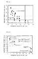
- FIG. 5 is a graph showing the relation between dislodgement of a gas sensor and release torque (N ⁇ m) and an estimated value ( ⁇ m) of a gap.
- FIG. 6 is a graph in which release torque (N ⁇ m) at 850°C is plotted with respect to an estimated value of a gap for each gas sensor installation structure obtained in examples.
- FIG. 1 illustrates a state in which the gas sensor 10 is installed in the pipe 6 by screwing the housing 5 into the boss 7 as described above.
- the relation between the coefficient of thermal expansion ( ⁇ 1 ) of the boss 7 which is the installation section and the coefficient of thermal expansion ( ⁇ 2 ) of the housing 5 is ⁇ 1 > ⁇ 2 , a gap is formed at the sealing section 3 when the temperature of the pipe 6 is increased, whereby the tightening force of the screw is decreased.
- the gas sensor of the present embodiment since the release torque at 850°C (1123 K) in the case where the housing 5 is screwed into the installation section (boss 7) and the estimated value X 1 of the gap calculated according to the above equation (1) are specific values in the relation between the coefficient of thermal expansion ( ⁇ 1 ) of the installation section and the length between the sealing surface and the top end of the installation section (L 1 ), the tightening force of the thread section 2 is maintained moderately. Therefore, the gas sensor of the present embodiment is rarely dislodged from the installation section (boss 7) even if the gas sensor is used in an installation environment in which vibration is applied either continuously or intermittently under high temperature conditions.
- the "release torque” used in the present invention means the torque necessary for dislodging the tightened product (gas sensor) from the installation section or the torque necessary for causing the tightening force between the tightened product and the installation section to be lost, and is a measured value which is actually measured using a torque gauge.
- the release torque at 850°C (1123 K) in the case where the housing is screwed into the installation section be 15 N ⁇ m or more and the estimated value X 1 of the gap calculated according to the above equation (1) be 20 ⁇ m or less. It is still more preferable that the release torque at 850°C (1123 K) be 20 N ⁇ m or more and the estimated value X 1 of the gap calculated according to the above equation (1) be 15 ⁇ m or less.
- the upper limit of the release torque is not limited in the present invention. It suffices that the release torque be equal to or less than the torque during tightening from the viewpoint of preventing deformation of the thread section, seizing of the screw, and the like.
- the lower limit of the estimated value X 1 of the gap in the present invention is not limited. There may be a case where the estimated value X 1 of the gap is a negative value since the estimated value X 1 is a theoretical value, and it suffices that the estimated value X 1 be about -10 ⁇ m or more.
- the gas sensor of the present invention may have a configuration in which the gasket 8 is provided to the sealing surface 4, as shown in FIG. 2.
- a gas sensor comprising a sensor element which has a function of detecting a specific gas component, a housing which contains the sensor element therein and has a sealing surface which forms a sealing section together with an installation section at the front in a direction in which the sensor element is inserted, and a rotating member which has a thread section which is formed outside the rotating member and is to be screwed into the installation section and can be rotated concentrically with a center axis of the housing, wherein release torque of the rotating member at 850°C (1123 K) in the case where the gas sensor is installed in the installation section by screwing the rotating member into the installation section is 9 N ⁇ m or more, and wherein an estimated value X 3 of a gap formed between the sealing surface and the installation section at 850°C (1123 K) calculated according to the following equation (3) is 31 ⁇ m or less.
- X 3 ( ⁇ m) ⁇ (L 1 x ⁇ 1 ) - (L 4 x ⁇ 4 ) - (L 5 ⁇ ⁇ 5 ) ⁇ ⁇ 1123
- X 3 represents an estimated value ( ⁇ m) of the gap
- L 1 represents a length ( ⁇ m) from the sealing surface to a top end of the installation section
- L 4 represents a length ( ⁇ m) from a bottom end to a top end of the thread section
- L 5 represents a length from the sealing surface to the bottom end of the thread section ( ⁇ m)
- ⁇ 1 represents a coefficient of thermal expansion (x 10 -6 /°C) of the installation section
- ⁇ 4 represents a coefficient of thermal expansion (x 10 -6 /°C) of the rotating member
- ⁇ 5 represents a coefficient of thermal expansion (x 10 -6 /°C) of the housing.
- the gas sensor of the present invention is described below taking the gas sensor installation structure shown in FIG. 3 as an example.
- FIG. 3 illustrates a state in which the rotating member (rotational hexagon 15) which can be rotated concentrically with the center axis of the housing 5 is disposed outside the housing 5, and the gas sensor 10 is installed by screwing the rotating member so that the sealing surface 4 is pressed against the boss 7 without rotating the housing 5.
- the relation between the coefficient of thermal expansion ( ⁇ 1 ) of the boss 7 which is the installation section and the coefficients of thermal expansion ( ⁇ 4 and ⁇ 5 ) of the housing 5 and the rotating member (rotational hexagon 15) is ⁇ 1 > ⁇ 4 and a 1 > ⁇ 5 , a gap is formed at the sealing section 3 when the temperature of the pipe 6 is increased, whereby the tightening force of the screw is decreased.
- the gas sensor of the present embodiment since the value of the release torque at 850°C (1123 K) in the case where the rotational hexagon 15 which is the rotating member is screwed into the installation section (boss 7) and the estimated value X 3 of the gap calculated according to the above equation (3) are specific values in the relation between the coefficient of thermal expansion ( ⁇ 1 ) of the installation section and the length (L 1 ) between the sealing surface and the top end of the installation section, the tightening force of the thread section 2 is maintained moderately. Therefore, the gas sensor of the present embodiment is rarely dislodged from the installation section (boss 7) even if the gas sensor is used in an installation environment in which vibration is applied either continuously or intermittently under high temperature conditions.
- the release torque at 850°C (1123 K) in the case where the rotating member is screwed into the installation section be 15 N ⁇ m or more and the estimated value X 3 of the gap calculated according to the above equation (3) be 20 ⁇ m or less. It is still more preferable that the release torque at 850°C (1123 K) be 20 N ⁇ m or more and the estimated value X 3 of the gap calculated according to the above equation (3) be 15 ⁇ m or less.
- the upper limit of the release torque is not limited. It suffices that the release torque be equal to or less than the torque during tightening from the viewpoint of preventing deformation of the thread section, seizing of the screw, and the like.
- the lower limit of the estimated value X 1 of the gap in the present invention is not limited. There may be a case where the estimated value X 3 of the gap is a negative value since the estimated value X 3 is a theoretical value, and it suffices that the estimated value X 3 be about -10 ⁇ m or more.
- an estimated value X 4 of the gap can be calculated according to the following equation (4):
- X 4 ( ⁇ m) ⁇ (L 1 ⁇ ⁇ 1 ) - (L 3 ⁇ ⁇ 3 ) - (L 4 x ⁇ 4 ) - (L 5 ⁇ ⁇ 5 ) ⁇ x 1123
- X 4 represents an estimated value ( ⁇ m) of the gap
- L 1 represents a length ( ⁇ m) from the sealing surface to a top end of the installation section
- L 3 represents a thickness ( ⁇ m) of the gasket
- L 4 represents a length ( ⁇ m) from a bottom end to a top end of the thread section
- L 5 represents a length ( ⁇ m) from the sealing surface to the bottom end of the thread section
- ⁇ 1 represents a coefficient of thermal expansion (x 10 -6 /°C) of the installation section
- ⁇ 3 represents a coefficient of thermal expansion
- the material for the gasket is preferably at least one material selected from the group consisting of 430 SS, 304 SS, 310 SS, 316 SS, and 321 SS. These materials can exhibit superior sealing properties at the sealing section and have excellent workability.
- the materials which make up the rotating member and the housing general-purpose materials are suitably used.
- the material for the rotating member at least one material selected from the group consisting of 430 SS, 304 SS, 310 SS, 316 SS, and 321 SS is preferably used.
- the material for the housing at least one material selected from the group consisting of 430 SS, 304 SS, 310 SS, 316 SS, and 321 SS is preferably used.
- the gas sensor installation structure of the present invention is described below taking the gas sensor installation structure shown in FIG. 1 as an example.
- the release torque of the housing at 850°C (1123 K) be 15 N ⁇ m or more and the estimated value X 5 of the gap calculated according to the above equation (5) be 20 ⁇ m or less. It is still more preferable that the release torque at 850°C (1123 K) be 20 N ⁇ m or more and the estimated value X 5 of the gap calculated according to the above equation (5) be 15 ⁇ m or less.
- the upper limit of the release torque is not limited. It suffices that the release torque be equal to or less than the torque during tightening from the viewpoint of preventing deformation of the thread section, seizing of the screw, and the like.
- the lower limit of the estimated value X 1 of the gap in the present invention is not limited. There may be a case where the estimated value X 5 of the gap is a negative value since the estimated value X 5 is a theoretical value, and it suffices that the estimated value X 5 be about -10 ⁇ m or more.
- the gas sensor installation structure of the present invention may have a configuration in which the sealing section 3 is formed through the gasket 8, as shown in FIG. 2.
- the material for the gasket is preferably at least one material selected from the group consisting of 430 SS, 304 SS, 310 SS, 316 SS, and 321 SS. These materials can exhibit superior sealing properties at the sealing section and have excellent workability.
- the gas sensor installation structure of the present invention is described below taking the gas sensor installation structure shown in FIG. 3 as an example.
- FIG. 3 illustrates a state in which the rotating member (rotational hexagon 15) which can be rotated concentrically with the center axis of the housing 5 is disposed outside the housing 5, and the gas sensor installation structure is formed by screwing the rotating member so that the sealing surface 4 is pressed against the boss 7 without rotating the housing 5.
- the relation between the coefficient of thermal expansion ( ⁇ 1 ) of the boss 7 which is the installation section and the coefficients of thermal expansion ( ⁇ 4 and ⁇ 5 ) of the housing 5 and the rotating member (rotational hexagon 15) is ⁇ 1 > ⁇ 4 and ⁇ 1 > ⁇ 5 , a gap is formed at the sealing section 3 when the temperature of the pipe 6 is increased, whereby the tightening force of the screw is decreased.
- the release torque at 850°C (1123 K) and the estimated value X 7 of the gap calculated according to the above equation (7) are specific values, the tightening force of the thread section 2 is maintained moderately. Therefore, even if the gas sensor installation structure of the present embodiment is used in an installation environment in which vibration is applied either continuously or intermittently under high temperature conditions, the gas sensor is significantly rarely dislodged from the installation section (boss 7).
- the release torque of the rotating member at 850°C (1123 K) be 15 N ⁇ m or more and the estimated value X 7 of the gap calculated according to the above equation (7) be 20 ⁇ m or less. It is still more preferable that the release torque of the rotating member at 850°C (1123 K) be 20 N ⁇ m or more and the estimated value X 7 of the gap calculated according to the above equation (7) be 15 ⁇ m or less.
- the upper limit of the release torque of the rotating member is not limited. It suffices that the release torque be equal to or less than the torque during tightening from the viewpoint of preventing deformation of the thread section, seizing of the screw, and the like.
- the lower limit of the estimated value X 1 of the gap in the present invention is not limited. There may be a case where the estimated value X 7 of the gap is a negative value since the estimated value X 7 is a theoretical value, and it suffices that the estimated value X 7 be about -10 ⁇ m or more.
- the gas sensor installation structure of the present invention may have a configuration in which the sealing section 3 is formed through the gasket 8, as shown in FIG. 4.
- an estimated value X 8 of the gap can be calculated according to the following equation (8).
- the material for the gasket is preferably at least one material selected from the group consisting of 430 SS, 304 SS, 310 SS, 316 SS, and 321 SS. These materials can exhibit superior sealing properties at the sealing section and have excellent workability.
- X 8 ( ⁇ m) ⁇ (L 1 ⁇ ⁇ 1 ) - (L 3 ⁇ ⁇ 3 ) - (L 4 ⁇ ⁇ 4 ) - (L 5 x ⁇ 5 ) ⁇ x 1123
- X 8 represents an estimated value ( ⁇ m) of the gap
- L 1 represents a length ( ⁇ m) from the sealing surface to a top end of the installation section
- L 3 represents a thickness ( ⁇ m) of the gasket
- L 4 represents a length ( ⁇ m) from a bottom end to a top end of the thread section
- L 5 represents a length ( ⁇ m) from the sealing surface to the bottom end of the thread section
- ⁇ 1 represents a coefficient of thermal expansion (x 10 -6 /°C) of the installation section
- ⁇ 3 represents a coefficient of thermal expansion (x 10 -6 /°C) of the gasket
- ⁇ 4 represents a coefficient of thermal expansion (x 10 -6 /°C) of the rotating member
- ⁇ 5 represents a coefficient
- the materials for the rotating member and the housing general-purpose materials are suitably used.
- the material for the rotating member at least one material selected from the group consisting of 430 SS, 304 SS, 310 SS, 316 SS, and 321 SS is preferably used.
- the material for the housing at least one material selected from the group consisting of 430 SS, 304 SS, 310 SS, 316 SS, and 321 SS is preferably used.
- the method for installing gas sensor is described below taking the gas sensor installation structure shown in FIG. 1 as an example.
- the housing In order to further reduce the possibility of dislodgement, it is preferable to screw the housing so that the release torque at 850°C (1123 K) is 15 N ⁇ m or more and the estimated value X 9 of the gap calculated according to the above equation (9) is 20 ⁇ m or less. It is still more preferable to screw the housing so that the release torque at 850°C (1123 K) is 20 N ⁇ m or more and the estimated value X 9 of the gap calculated according to the above equation (9) is 15 ⁇ m or less.
- the upper limit of the release torque is not limited. It suffices that the release torque be equal to or less than the torque during tightening from the viewpoint of preventing deformation of the thread section, seizing of the screw, and the like.
- the lower limit of the estimated value X 1 of the gap in the present invention is not limited. There may be a case where the estimated value X 9 of the gap is a negative value since the estimated value X 9 is a theoretical value, and it suffices that the estimated value X 9 be about -10 ⁇ m or more.
- the sealing section 3 may be formed through the gasket 8, as shown in FIG. 2.
- the method for installing gas sensor is described below taking the gas sensor installation structure shown in FIG. 3 as an example.
- FIG. 3 illustrates a state in which the rotating member (rotational hexagon 15) which can be rotated concentrically with the center axis of the housing 5 is disposed outside the housing 5, and the gas sensor installation structure is formed by screwing the rotating member so that the sealing surface 4 is pressed against the boss 7 without rotating the housing 5.
- the relation between the coefficient of thermal expansion ( ⁇ 1 ) of the boss 7 which is the installation section and the coefficients of thermal expansion ( ⁇ 4 and ⁇ 5 ) of the housing 5 and the rotating member (rotational hexagon 15) is ⁇ 1 > ⁇ 4 and ⁇ 1 > ⁇ 5
- a gap is formed at the sealing section 3 when the temperature of the pipe 6 is increased in this state, whereby the tightening force of the thread section 3 is decreased.
- the rotating member In order to further reduce the possibility of dislodgement, it is preferable to screw the rotating member so that that the release torque at 850°C (1123 K) is 15 N ⁇ m or more and the estimated value X 11 of the gap calculated according to the above equation (11) is 20 ⁇ m or less. It is still more preferable to screw the rotating member so that the release torque at 850°C (1123 K) is 20 N ⁇ m or more and the estimated value X 11 of the gap calculated according to the above equation (11) is 15 ⁇ m or less.
- the upper limit of the release torque is not limited. It suffices that the release torque be equal to or less than the torque during tightening from the viewpoint of preventing deformation of the thread section, seizing of the screw, and the like.
- the lower limit of the estimated value X 11 of the gap in the present invention is not limited. There may be a case where the estimated value X 11 of the gap is a negative value since the estimated value X 11 is a theoretical value. It suffices that the estimated value X 11 be about -10 ⁇ m or more.
- the sealing section 3 may be formed through the gasket 8, as shown in FIG. 4.
- the materials for the gasket, the rotating member, and the housing general-purpose materials are suitably used.
- the material for the gasket at least one material selected from the group consisting of 430 SS, 304 SS, 310 SS, 316 SS, and 321 SS is preferably used.
- the material for the rotating member at least one material selected from the group consisting of 430 SS, 304 SS, 310 SS, 316 SS, and 321 SS is preferably used.
- the material for the housing at least one material selected from the group consisting of 430 SS, 304 SS, 310 SS, 316 SS, and 321 SS is preferably used.
- Example 1 Each constituent member formed of materials shown in Table 1 was provided.
- the rotational hexagon was screwed into the boss at a tightening torque of 30 N ⁇ m or more at room temperature to obtain a gas sensor installation structure having a structure shown in FIG. 3 (samples Nos. 1-13).
- the length (L 1 : mm) from the sealing surface to the top end of the boss (installation section) was as shown in Table 1.
- the resulting gas sensor installation structure was allowed to stand under high temperature conditions of 850°C, and the release torque (N ⁇ m) of the rotational hexagon was measured.
- the estimated value ( ⁇ m) of the gap formed between the sealing surface and the boss was calculated from the coefficient of thermal expansion ( ⁇ 10 -6 /°C) of the materials for each member and the lengths (mm) at each point (L 1 and L 3 to L 5 ).
- FIG. 5 shows a graph in which the release torque (N ⁇ m) is plotted with respect to the resulting estimated values.
- the resulting gas sensor installation structure was subjected to a vibration test to confirm whether or not the gas sensor was dislodged. The results are shown in FIG. 5. Sample No.
- the gas sensor is not dislodged from the boss which is the installation section in the case where the release torque of the rotational hexagon at 850°C (1123 K) is 9 N ⁇ m or more and the estimated value of the gap is 31 ⁇ m or less.
- the gas sensor can be prevented from being dislodged in advance by appropriately selecting the materials and dimensions of the rotational hexagon, the gasket, and the housing for the material and dimensions of the boss, and appropriately controlling the tightening force (release torque) of the rotational hexagon.
- the release torque of the rotational hexagon (rotating member) of a gas sensor installation structure was measured according to the following method.
- the gas sensor installation structure was formed by installing the gas sensor in the pipe.
- the gas sensor installation structure was then heated by allowing gas at 850°C to flow through the pipe. After allowing the gas sensor installation structure to stand for two hours in this state, the release torque measured using a torque gauge was taken as the release torque (N ⁇ m) at 850°C.
- the gas sensor installation structure thus obtained was subjected to a vibration test using a test equipment and conditions shown in Table 2.
- Each constituent member formed of materials shown in Table 3 was provided.
- the rotational hexagon was screwed into the boss at a tightening torque of 60 N ⁇ m or 40 N ⁇ m at room temperature to obtain a gas sensor installation structure having a structure shown in FIG. 3.
- the gas sensor installation structure thus obtained was allowed to stand under high temperature conditions of 850°C, and the release torque (N ⁇ m) of the rotational hexagon was measured.
- the estimated value ( ⁇ m) of the gap formed between the sealing surface and the boss was calculated from the coefficients of thermal expansion (x 10 -6 /°C) of the materials for each member and the lengths (mm) at each point (L 1 and L 3 to L 5 ).
- Table 3 shows the release torque (N ⁇ m) at 850°C and the estimated value ( ⁇ m) of the gap.
- FIG. 6 shows a graph in which the release torque (N ⁇ m) at 850°C is plotted with respect to the estimated value of the gap.
- the gas sensor installation structure thus obtained was subjected to the vibration test to confirm whether or not the gas sensor was dislodged.
- the gas sensor was not dislodged in Examples 1-4, the gas sensor was dislodged in Comparative Examples 1 and 2 (Table 3). Therefore, as shown in FIG. 6, it was confirmed that the gas sensor is not dislodged from the boss which is the installation section in the case where the release torque of the rotational hexagon at 850°C (1123 K) is 9 N ⁇ m or more and the estimated value of the gap is 31 ⁇ m or less.
- the gas sensor of the present invention rarely allows the tightening force of the screw to be decreased even if the gas sensor is installed and used under high temperature conditions, and is rarely dislodged from the installation section even if vibration is applied, since the release torque at a specific temperature in the case where the housing or the rotating member which is the constituent member is screwed into the installation section and the estimated value of the gap formed between the sealing surface and the installation section are specific values.
- the gas sensor installation structure of the present invention rarely allows the tightening force of the screw to be decreased even if the gas sensor installation structure is installed and used under high temperature conditions, and the gas sensor is rarely dislodged from the installation section even if vibration is applied, since the release torque of the housing or the rotating member at a specific temperature and the estimated value of the gap formed between the sealing surface and the installation section are specific values.
- the housing or the rotating member is screwed so that the release torque at a specific temperature and the estimated value of the gap formed between the sealing surface and the installation section are specific values, a gas sensor installation structure in which the gas sensor is significantly rarely dislodged from the installation section can be obtained.
Landscapes
- Chemical & Material Sciences (AREA)
- Health & Medical Sciences (AREA)
- Life Sciences & Earth Sciences (AREA)
- Analytical Chemistry (AREA)
- General Health & Medical Sciences (AREA)
- Pathology (AREA)
- Immunology (AREA)
- Physics & Mathematics (AREA)
- Engineering & Computer Science (AREA)
- Biochemistry (AREA)
- General Physics & Mathematics (AREA)
- Combustion & Propulsion (AREA)
- Medicinal Chemistry (AREA)
- Food Science & Technology (AREA)
- Molecular Biology (AREA)
- Chemical Kinetics & Catalysis (AREA)
- Electrochemistry (AREA)
- Measuring Oxygen Concentration In Cells (AREA)
- Gasket Seals (AREA)
Applications Claiming Priority (2)
| Application Number | Priority Date | Filing Date | Title |
|---|---|---|---|
| JP2002095842 | 2002-03-29 | ||
| JP2002095842A JP3866134B2 (ja) | 2002-03-29 | 2002-03-29 | ガスセンサ取付構造体、及びガスセンサ取付方法 |
Publications (3)
| Publication Number | Publication Date |
|---|---|
| EP1365233A2 true EP1365233A2 (de) | 2003-11-26 |
| EP1365233A3 EP1365233A3 (de) | 2004-08-18 |
| EP1365233B1 EP1365233B1 (de) | 2014-07-23 |
Family
ID=28671817
Family Applications (1)
| Application Number | Title | Priority Date | Filing Date |
|---|---|---|---|
| EP03251971.2A Expired - Lifetime EP1365233B1 (de) | 2002-03-29 | 2003-03-28 | Gassensoreinbauvorrichtung und Verfahren zum Einbau von Gassensoren |
Country Status (3)
| Country | Link |
|---|---|
| US (2) | US6796175B2 (de) |
| EP (1) | EP1365233B1 (de) |
| JP (1) | JP3866134B2 (de) |
Families Citing this family (8)
| Publication number | Priority date | Publication date | Assignee | Title |
|---|---|---|---|---|
| JP3866134B2 (ja) * | 2002-03-29 | 2007-01-10 | 日本碍子株式会社 | ガスセンサ取付構造体、及びガスセンサ取付方法 |
| JP2005164246A (ja) * | 2003-11-28 | 2005-06-23 | Ngk Spark Plug Co Ltd | ガスセンサ |
| JP4258534B2 (ja) * | 2006-07-18 | 2009-04-30 | トヨタ自動車株式会社 | 電源システム |
| JP5106248B2 (ja) * | 2008-05-26 | 2012-12-26 | Udトラックス株式会社 | NOxセンサの異常判定装置 |
| JP5469693B2 (ja) | 2011-04-08 | 2014-04-16 | 日本特殊陶業株式会社 | センサ及びセンサ取付構造体 |
| JP6424789B2 (ja) | 2015-02-12 | 2018-11-21 | 株式会社デンソー | ガスセンサ |
| DE102015209262A1 (de) * | 2015-05-21 | 2016-11-24 | Bayerische Motoren Werke Aktiengesellschaft | Abgasanlage mit einem Gassensor, insbesondere mit einem Partikelsensor |
| JP6784504B2 (ja) * | 2016-04-08 | 2020-11-11 | 日本特殊陶業株式会社 | 微粒子センサ |
Citations (3)
| Publication number | Priority date | Publication date | Assignee | Title |
|---|---|---|---|---|
| US4526672A (en) | 1984-03-23 | 1985-07-02 | Axia Incorporated | Oxygen sensor |
| WO1997029364A1 (en) | 1996-02-12 | 1997-08-14 | General Motors Corporation | Sensor with glass seal |
| JP2001221769A (ja) | 2000-02-03 | 2001-08-17 | Ngk Insulators Ltd | ガスセンサ |
Family Cites Families (14)
| Publication number | Priority date | Publication date | Assignee | Title |
|---|---|---|---|---|
| US4096752A (en) * | 1976-07-06 | 1978-06-27 | Production Data Inc. | Oil well logging probe assembly |
| US4199424A (en) * | 1978-09-13 | 1980-04-22 | The Bendix Corporation | Protective shield for sensing means |
| JPH05232062A (ja) | 1991-12-25 | 1993-09-07 | Ngk Spark Plug Co Ltd | ガスセンサ |
| US5329806A (en) | 1993-05-11 | 1994-07-19 | General Motors Corporation | Exhaust sensor with tubular shell |
| US5401962A (en) * | 1993-06-14 | 1995-03-28 | Ferran Scientific | Residual gas sensor utilizing a miniature quadrupole array |
| DE4417665A1 (de) * | 1994-05-20 | 1995-11-30 | Testo Gmbh & Co | Meßanordnung zur Untersuchung gasförmiger Medien |
| EP0704697A1 (de) * | 1994-09-27 | 1996-04-03 | General Motors Corporation | Abgassensor mit keramischem Rohr in einer Metalltubepackung |
| JPH08278280A (ja) | 1995-04-07 | 1996-10-22 | Nippondenso Co Ltd | ガスセンサ |
| DE19608543A1 (de) * | 1996-03-06 | 1997-09-11 | Bosch Gmbh Robert | Meßfühler |
| JP3635197B2 (ja) * | 1997-11-28 | 2005-04-06 | 日本特殊陶業株式会社 | ガスセンサ |
| US6302402B1 (en) * | 1999-07-07 | 2001-10-16 | Air Products And Chemicals, Inc. | Compliant high temperature seals for dissimilar materials |
| US6673224B2 (en) * | 2000-06-30 | 2004-01-06 | Denso Corporation | Sealing structure of gas sensor |
| JP2002090335A (ja) * | 2000-09-18 | 2002-03-27 | Ngk Spark Plug Co Ltd | ガスセンサ |
| JP3866134B2 (ja) * | 2002-03-29 | 2007-01-10 | 日本碍子株式会社 | ガスセンサ取付構造体、及びガスセンサ取付方法 |
-
2002
- 2002-03-29 JP JP2002095842A patent/JP3866134B2/ja not_active Expired - Lifetime
-
2003
- 2003-03-25 US US10/396,633 patent/US6796175B2/en not_active Expired - Lifetime
- 2003-03-28 EP EP03251971.2A patent/EP1365233B1/de not_active Expired - Lifetime
-
2004
- 2004-05-26 US US10/854,728 patent/US6857316B2/en not_active Expired - Lifetime
Patent Citations (3)
| Publication number | Priority date | Publication date | Assignee | Title |
|---|---|---|---|---|
| US4526672A (en) | 1984-03-23 | 1985-07-02 | Axia Incorporated | Oxygen sensor |
| WO1997029364A1 (en) | 1996-02-12 | 1997-08-14 | General Motors Corporation | Sensor with glass seal |
| JP2001221769A (ja) | 2000-02-03 | 2001-08-17 | Ngk Insulators Ltd | ガスセンサ |
Non-Patent Citations (1)
| Title |
|---|
| J E POPE ET AL.: "Rues of Thumb for Mechanical Engineers", 1997, GULF PUBLISHING COMPANY, pages: 317 |
Also Published As
| Publication number | Publication date |
|---|---|
| JP2003294685A (ja) | 2003-10-15 |
| US20030188568A1 (en) | 2003-10-09 |
| US20040216513A1 (en) | 2004-11-04 |
| US6857316B2 (en) | 2005-02-22 |
| JP3866134B2 (ja) | 2007-01-10 |
| EP1365233A3 (de) | 2004-08-18 |
| EP1365233B1 (de) | 2014-07-23 |
| US6796175B2 (en) | 2004-09-28 |
Similar Documents
| Publication | Publication Date | Title |
|---|---|---|
| US7600433B2 (en) | Pressure sensor with roughened and treated surface for improving adhesive strength and method of manufacturing the sensor | |
| US7287433B2 (en) | Pressure sensor | |
| US6796175B2 (en) | Gas sensor, gas sensor installation structure, and method for installing gas sensor | |
| US9182297B2 (en) | Exhaust gas temperature sensor including a vibration reducing and/or modifying sleeve | |
| US20080205485A1 (en) | Installation mechanism for temperature sensor | |
| US9476775B2 (en) | Exhaust gas temperature sensor including strain relief and/or anti-vibration sleeve | |
| US8122765B2 (en) | Membrane protection for a sensor having a membrane, and sensor having a membrane and membrane protection | |
| JP2000121474A (ja) | 自動車用センサの取付け構造及び半導体圧力センサ | |
| KR100356778B1 (ko) | 멤브레인 압력 센서 | |
| EP0191251A1 (de) | Zweirichtungsdichtung | |
| JP2009282034A (ja) | 危険な用途に用いられるゲージ式圧力センサ | |
| US7395720B2 (en) | Apparatus for securing a measuring sensor on a pipeline | |
| RU2397462C1 (ru) | Тонкопленочный датчик давления | |
| US20080069179A1 (en) | Method for operating a sensor arrangement | |
| US5852245A (en) | Piezoelectric pressure sensor suitable for sensing pressure at high temperatures | |
| EP1619487B1 (de) | Dehnungssensor und entsprechendes Herstellungsverfahren. | |
| KR20050060004A (ko) | 산소 센서 | |
| US5904459A (en) | Fastener apparatus and system with self-setting torque and over-torque protection | |
| US20040070153A1 (en) | Metallic flat seal and method for the production thereof | |
| US20160084723A1 (en) | Pressure Sensor | |
| US20040146084A1 (en) | Component exposed to thermal loads | |
| US20020148279A1 (en) | Gas sensor | |
| US20240337514A1 (en) | Field device with a sensor for detecting a physical measured variable, and clamping element for fastening a housing of a field device to a sensor neck | |
| WO2008115131A1 (en) | A sensor device | |
| JP6485331B2 (ja) | ガスセンサ |
Legal Events
| Date | Code | Title | Description |
|---|---|---|---|
| PUAI | Public reference made under article 153(3) epc to a published international application that has entered the european phase |
Free format text: ORIGINAL CODE: 0009012 |
|
| AK | Designated contracting states |
Kind code of ref document: A2 Designated state(s): AT BE BG CH CY CZ DE DK EE ES FI FR GB GR HU IE IT LI LU MC NL PT RO SE SI SK TR |
|
| AX | Request for extension of the european patent |
Extension state: AL LT LV MK |
|
| PUAL | Search report despatched |
Free format text: ORIGINAL CODE: 0009013 |
|
| AK | Designated contracting states |
Kind code of ref document: A3 Designated state(s): AT BE BG CH CY CZ DE DK EE ES FI FR GB GR HU IE IT LI LU MC NL PT RO SE SI SK TR |
|
| AX | Request for extension of the european patent |
Extension state: AL LT LV MK |
|
| RIC1 | Information provided on ipc code assigned before grant |
Ipc: 7G 01N 27/407 A Ipc: 7G 01N 27/12 B Ipc: 7G 01N 27/416 B Ipc: 7F 01N 7/00 B |
|
| 17P | Request for examination filed |
Effective date: 20041123 |
|
| AKX | Designation fees paid |
Designated state(s): DE FR GB |
|
| RBV | Designated contracting states (corrected) |
Designated state(s): DE FR GB |
|
| APBK | Appeal reference recorded |
Free format text: ORIGINAL CODE: EPIDOSNREFNE |
|
| APBN | Date of receipt of notice of appeal recorded |
Free format text: ORIGINAL CODE: EPIDOSNNOA2E |
|
| APBR | Date of receipt of statement of grounds of appeal recorded |
Free format text: ORIGINAL CODE: EPIDOSNNOA3E |
|
| APAF | Appeal reference modified |
Free format text: ORIGINAL CODE: EPIDOSCREFNE |
|
| APBT | Appeal procedure closed |
Free format text: ORIGINAL CODE: EPIDOSNNOA9E |
|
| GRAP | Despatch of communication of intention to grant a patent |
Free format text: ORIGINAL CODE: EPIDOSNIGR1 |
|
| RIC1 | Information provided on ipc code assigned before grant |
Ipc: G01N 27/407 20060101AFI20140122BHEP Ipc: G01N 33/00 20060101ALI20140122BHEP Ipc: G01N 27/12 20060101ALI20140122BHEP |
|
| INTG | Intention to grant announced |
Effective date: 20140220 |
|
| RIN1 | Information on inventor provided before grant (corrected) |
Inventor name: KURACHI, HIROSHI Inventor name: IKOMA, NOBUKAZU Inventor name: LEE, SANG JAE |
|
| GRAS | Grant fee paid |
Free format text: ORIGINAL CODE: EPIDOSNIGR3 |
|
| GRAA | (expected) grant |
Free format text: ORIGINAL CODE: 0009210 |
|
| AK | Designated contracting states |
Kind code of ref document: B1 Designated state(s): DE FR GB |
|
| REG | Reference to a national code |
Ref country code: GB Ref legal event code: FG4D |
|
| REG | Reference to a national code |
Ref country code: DE Ref legal event code: R096 Ref document number: 60346515 Country of ref document: DE Effective date: 20140828 |
|
| REG | Reference to a national code |
Ref country code: DE Ref legal event code: R097 Ref document number: 60346515 Country of ref document: DE |
|
| PLBE | No opposition filed within time limit |
Free format text: ORIGINAL CODE: 0009261 |
|
| STAA | Information on the status of an ep patent application or granted ep patent |
Free format text: STATUS: NO OPPOSITION FILED WITHIN TIME LIMIT |
|
| 26N | No opposition filed |
Effective date: 20150424 |
|
| GBPC | Gb: european patent ceased through non-payment of renewal fee |
Effective date: 20150328 |
|
| REG | Reference to a national code |
Ref country code: FR Ref legal event code: ST Effective date: 20151130 |
|
| PG25 | Lapsed in a contracting state [announced via postgrant information from national office to epo] |
Ref country code: GB Free format text: LAPSE BECAUSE OF NON-PAYMENT OF DUE FEES Effective date: 20150328 |
|
| PG25 | Lapsed in a contracting state [announced via postgrant information from national office to epo] |
Ref country code: FR Free format text: LAPSE BECAUSE OF NON-PAYMENT OF DUE FEES Effective date: 20150331 |
|
| PGFP | Annual fee paid to national office [announced via postgrant information from national office to epo] |
Ref country code: DE Payment date: 20220203 Year of fee payment: 20 |
|
| REG | Reference to a national code |
Ref country code: DE Ref legal event code: R071 Ref document number: 60346515 Country of ref document: DE |