EP1363389A2 - Commande d'un onduleur - Google Patents
Commande d'un onduleur Download PDFInfo
- Publication number
- EP1363389A2 EP1363389A2 EP03076276A EP03076276A EP1363389A2 EP 1363389 A2 EP1363389 A2 EP 1363389A2 EP 03076276 A EP03076276 A EP 03076276A EP 03076276 A EP03076276 A EP 03076276A EP 1363389 A2 EP1363389 A2 EP 1363389A2
- Authority
- EP
- European Patent Office
- Prior art keywords
- control section
- control unit
- voltage
- inverter
- circuit
- Prior art date
- Legal status (The legal status is an assumption and is not a legal conclusion. Google has not performed a legal analysis and makes no representation as to the accuracy of the status listed.)
- Withdrawn
Links
Images
Classifications
-
- H—ELECTRICITY
- H02—GENERATION; CONVERSION OR DISTRIBUTION OF ELECTRIC POWER
- H02M—APPARATUS FOR CONVERSION BETWEEN AC AND AC, BETWEEN AC AND DC, OR BETWEEN DC AND DC, AND FOR USE WITH MAINS OR SIMILAR POWER SUPPLY SYSTEMS; CONVERSION OF DC OR AC INPUT POWER INTO SURGE OUTPUT POWER; CONTROL OR REGULATION THEREOF
- H02M7/00—Conversion of AC power input into DC power output; Conversion of DC power input into AC power output
- H02M7/42—Conversion of DC power input into AC power output without possibility of reversal
- H02M7/44—Conversion of DC power input into AC power output without possibility of reversal by static converters
- H02M7/48—Conversion of DC power input into AC power output without possibility of reversal by static converters using discharge tubes with control electrode or semiconductor devices with control electrode
- H02M7/53—Conversion of DC power input into AC power output without possibility of reversal by static converters using discharge tubes with control electrode or semiconductor devices with control electrode using devices of a triode or transistor type requiring continuous application of a control signal
- H02M7/537—Conversion of DC power input into AC power output without possibility of reversal by static converters using discharge tubes with control electrode or semiconductor devices with control electrode using devices of a triode or transistor type requiring continuous application of a control signal using semiconductor devices only, e.g. single switched pulse inverters
- H02M7/5387—Conversion of DC power input into AC power output without possibility of reversal by static converters using discharge tubes with control electrode or semiconductor devices with control electrode using devices of a triode or transistor type requiring continuous application of a control signal using semiconductor devices only, e.g. single switched pulse inverters in a bridge configuration
- H02M7/53871—Conversion of DC power input into AC power output without possibility of reversal by static converters using discharge tubes with control electrode or semiconductor devices with control electrode using devices of a triode or transistor type requiring continuous application of a control signal using semiconductor devices only, e.g. single switched pulse inverters in a bridge configuration with automatic control of output voltage or current
- H02M7/53873—Conversion of DC power input into AC power output without possibility of reversal by static converters using discharge tubes with control electrode or semiconductor devices with control electrode using devices of a triode or transistor type requiring continuous application of a control signal using semiconductor devices only, e.g. single switched pulse inverters in a bridge configuration with automatic control of output voltage or current with digital control
Definitions
- the present invention relates to a control unit for controlling an inverter having a bridge circuit provided with controllable semiconductor switches, which bridge circuit converts a direct voltage fed to the inverter into an alternating voltage of variable frequency and amplitude, said control unit controlling the semiconductor switches by pulse-width modulation (PWM) to produce an output voltage of the inverter.
- PWM pulse-width modulation
- the invention relates especially to a PWM inverter control arrangement which comprises a control circuit at ground potential used e.g. for a customer interface and a control circuit at main circuit potential, containing e.g. measuring circuits and circuits producing control signals for power semiconductor switches.
- Such an inverter is applicable for use e.g. in a frequency converter in which the alternating voltage of a three-phase supply network is rectified by a rectifier circuit to produce an intermediate circuit direct voltage and then inverted by means of an inverter to produce a three-phase alternating voltage of variable frequency and amplitude for feeding e.g. a three-phase cage induction motor.
- PWM frequency converters are generally used to control the rotational speed of a cage induction motor, which is the commonest motor type in industry.
- An output voltage of variable amplitude and frequency is generated by means of the power semiconductor switches of an inverter.
- pulse amplifier circuits at main circuit potential i.e. at the potential of the power semiconductor switches are needed.
- measuring circuits which are normally also at main circuit potential.
- the control circuit processing the signals pertaining to the customer interface again has to be at ground potential for reasons of safety. Therefore, galvanic isolation is required between the control circuit unit at ground potential and the control circuits at main circuit potential.
- a common practice for providing galvanic isolation between the units is to use serial communication via optoisolators or optical fibers.
- serial communication via optoisolators or optical fibers.
- Such an arrangement is known e.g. from patent specification EP0469872, which discloses a system for the control of an adjustable-frequency AC inverter using two serial data channels: one channel for transmitting reference values to a control circuit at main circuit potential and a second channel for transmitting measurement and other feedback data to a control circuit at ground potential.
- the pulse pattern of the voltage produced by the inverter is normally computed either by a microprocessor or an ASIC circuit designed for this purpose.
- the generation of the pulse pattern is normally based on a predetermined algorithm, e.g. a sine-triangle comparison.
- the modern efficient microprocessors allow both the functions required for the control of the customer interface and the functions needed for controlling the main circuit to be performed by the same processor, which is normally placed in a the control unit section at ground potential.
- the generation of a pulse pattern implemented in the aforesaid manner involves the problem that the pulse pattern actually produced in the output voltage is not exactly of the desired form. Deviations arise e.g. from signal processing delays in the pulse amplifiers, switching delays in the power semiconductor switches and the required so-called dead time between the conduction periods of the upper and lower arms of the phase switch. Further errors result from a fast variation of the d.c. intermediate circuit voltage. Especially at low frequencies, at which a large number of switching actions occur during a single cycle of the output voltage, the errors clearly distort the output voltage.
- the voltage error can be compensated by measuring the output voltage produced and taking the error into account in connection with the next switching instant. Especially if the pulse pattern is generated at ground potential, the large voltage difference requires the use of difficult and expensive measuring circuits which reduce the ground impedance of the device and may cause problems in the earth-leakage monitoring circuits of the supply network.
- the object of the present invention is to achieve a control system for the control of a PWM-controlled inverter that is better than prior-art solutions, in which system the output voltage is always correct regardless of frequency, power-stage dead time or variations of the intermediate circuit voltage, wherein the phase switches do not have to perform any unnecessary actions, the switching losses being thereby reduced, wherein the angle of the output voltage vector is continuously known, allowing easier motor adjustment especially in difficult applications, and wherein the distribution of tasks between the control unit at ground potential and the control unit at main circuit potential is natural, so that no difficult main circuit measurements are needed and no ground impedance problems caused by them arise.
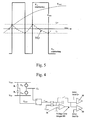
- this is achieved by calculating in the control unit section at ground potential the instantaneous value of the voltage vector of the output phases, which value is transmitted in serial format over a galvanically isolated channel to the control unit section at main circuit potential, where the modulation, i.e. determination of the phase switch positions is carried out by forming the time integral of the difference between the reference and actual values of the phase voltages, comparing this difference to a positive limit and a negative limit, and if the time integral exceeds the positive or the negative limit, the phase switch is turned accordingly either to the up position or to the down position.
- the angle and amplitude of the output voltage vector is given in the channel between the galvanically isolated control circuits.
- the reference values of the instantaneous voltages of at least two phase voltages are given in the channel between the galvanically isolated control circuits.
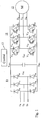
- Fig. 1 represents a prior-art voltage-controlled three-phase PWM frequency converter comprising a rectifier bridge 10 for the rectification of a three-phase alternating voltage consisting of phase voltages U R , U S , U T to produce an intermediate circuit direct voltage U DC and an inverter bridge 11 for DC/AC conversion of the intermediate circuit direct voltage into a three-phase alternating voltage of variable frequency and amplitude having phase voltages U U , U V , U W .
- the frequency converter feeds a three-phase cage induction motor (M) 12.
- the inverter bridge 11 is a full-wave bridge having in the upper and lower arms of the three phases controllable semiconductor switches V 11 - V 16 with diodes D 11 - D 16 connected in inverse-parallel with them.
- the inverter control unit 13 controls the semiconductor switches V 11 - V 16 of each phase (V 11 , V 14 in phase U; V 12 , V 15 in phase V, and V 13 , V 16 in phase W) by pulse-width
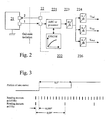
- Fig. 2 represents the inverter control unit 13, in which the outward interface part 21 of the control system is grounded and galvanically isolated from the control functions 22 immediately relating to the main circuit by means of two optically isolated serial data channels 1 and 2, implemented e.g. using optical fibers.
- One of the channels is used for the transmission of reference values to the control unit at main circuit potential and the other for the transmission of feedback data.
- control unit section 21 also takes care of actions relating to the adjustment of the output voltage, such as the computations relating to motor adjustment, actions associated with supply network failures, etc., and sends the values of the output voltage vector obtained as a final result to the control circuits 22 of the main circuit.
- Control unit section 22 performs the modulation, i.e. the determination of the phase switch positions, main circuit measurements and actions relating to immediate protection of the power stage.
- channel 1 is used for transmitting reference values by giving the angle and amplitude of the output voltage vector during operation, instead of which it is also possible give the instantaneous values of the phase voltages.
- the reference values are given precisely at predetermined intervals, e.g. at every 50 ⁇ s.
- the direction of rotation of the vector angle also determines the direction of rotation of the motor.
- channel 1 can also be used for other actions, such as carrying out inquiries concerning the power stage in connection with start-up and giving a switching frequency reference and start/stop data.
- Channel 2 is used for the transmission of feedback signals: motor currents, DC voltage, temperatures and malfunction and warning notices during operation and for responding to inquiries relating to the power stage in connection with start-up.
- channel 1 transmits the angle and amplitude of the output voltage vector
- the unscaled instantaneous values of the phase voltages are read from memory on the basis of an angle reference and multiplied by an amplitude reference. If the sinusoidal phase voltage reference curve is combined with the 3 rd harmonic, which is a well-known expedient used to achieve a larger output voltage, then the quarter period (90°) values of the sine curve have to be programmed in memory. If the sine curve is not combined with the 3 rd harmonic, only the 60° values have to be stored in memory.
- the readings obtained from the memory 222 are multiplied in a microcircuit 221 by the amplitude reference and D/A-converted in a converter 223 to produce in reference value units 224, 225 and 226 analog instantaneous-value references U Uref , U Vref and U Wref of the phase voltages when the 3 rd harmonic has been mixed with the sine curve to reach a full output voltage. If the 3 rd harmonic has not been mixed with the sine curve, it is sufficient to D/A convert the instantaneous value references, the 3 rd phase voltage being obtained by summing.
- the modulation i.e. determination of the positions of the phase switches V 11 - V 16 is performed by coupling as presented in Fig. 4 as follows e.g. for phase U:
Landscapes
- Engineering & Computer Science (AREA)
- Power Engineering (AREA)
- Inverter Devices (AREA)
- Control Of Ac Motors In General (AREA)
Applications Claiming Priority (2)
| Application Number | Priority Date | Filing Date | Title |
|---|---|---|---|
| FI20020933 | 2002-05-17 | ||
| FI20020933A FI112558B (fi) | 2002-05-17 | 2002-05-17 | Vaihtosuuntaajan ohjaus |
Publications (2)
| Publication Number | Publication Date |
|---|---|
| EP1363389A2 true EP1363389A2 (fr) | 2003-11-19 |
| EP1363389A3 EP1363389A3 (fr) | 2006-02-22 |
Family
ID=8563959
Family Applications (1)
| Application Number | Title | Priority Date | Filing Date |
|---|---|---|---|
| EP03076276A Withdrawn EP1363389A3 (fr) | 2002-05-17 | 2003-05-02 | Commande d'un onduleur |
Country Status (3)
| Country | Link |
|---|---|
| US (1) | US6807074B2 (fr) |
| EP (1) | EP1363389A3 (fr) |
| FI (1) | FI112558B (fr) |
Families Citing this family (11)
| Publication number | Priority date | Publication date | Assignee | Title |
|---|---|---|---|---|
| US7239034B2 (en) * | 2004-03-16 | 2007-07-03 | Tecogen, Inc. | Engine driven power inverter system with cogeneration |
| FI121491B (fi) * | 2004-11-11 | 2010-11-30 | Vacon Oyj | Taajuusmuuttajan ylijännitesuojaus |
| FI121803B (fi) * | 2005-05-03 | 2011-04-15 | Vacon Oyj | Taajuusmuuttajan valvontajärjestely |
| US7932693B2 (en) * | 2005-07-07 | 2011-04-26 | Eaton Corporation | System and method of controlling power to a non-motor load |
| US7468595B2 (en) * | 2005-07-26 | 2008-12-23 | Eaton Corporation | System and method of controlling the start-up of an adjustable speed motor drive based sinusoidal output power conditioner |
| US7193388B1 (en) | 2006-02-02 | 2007-03-20 | Emerson Electric Co. | Offset PWM signals for multiphase motor |
| WO2008109713A2 (fr) * | 2007-03-05 | 2008-09-12 | Jorge Sanchez | Procédé et micrologiciel pour contrôler une tension d'inverseur par fréquence de signal de commande |
| BR112017022364A2 (pt) | 2015-04-20 | 2018-07-10 | Eaton Corp | método para reduzir interferência eletromagnética em aplicações de circuito de comutação |
| DE112016007532T5 (de) * | 2016-12-21 | 2019-09-26 | Vacon Oy | Priorisierte serielle kommunikation |
| JP7390881B2 (ja) * | 2019-12-11 | 2023-12-04 | 富士フイルムヘルスケア株式会社 | 電力変換装置及びx線画像撮影装置、モータードライブ装置 |
| WO2022272279A1 (fr) | 2021-06-23 | 2022-12-29 | Tecogen Inc. | Système d'alimentation hybride à générateur électrique et source d'énergie auxiliaire |
Family Cites Families (9)
| Publication number | Priority date | Publication date | Assignee | Title |
|---|---|---|---|---|
| GB2186127B (en) * | 1986-01-11 | 1990-03-21 | Hitachi Ltd | Apparatus for controlling power transducers |
| JPS6373898A (ja) * | 1986-09-12 | 1988-04-04 | Matsushita Electric Ind Co Ltd | インバ−タ装置 |
| JPH0469872A (ja) | 1990-07-11 | 1992-03-05 | Nec Gumma Ltd | フレキシブルデイスク装置のステツピングモータ駆動回路 |
| US5045988A (en) * | 1990-07-31 | 1991-09-03 | Eaton Corporation | Isolated adjustable frequency AC inverter control |
| US4994950A (en) * | 1990-07-31 | 1991-02-19 | Eaton Corporation | Waveform generator for inverter control |
| JP3116698B2 (ja) | 1993-12-22 | 2000-12-11 | 松下電器産業株式会社 | インバータの電圧検出装置 |
| KR200154582Y1 (ko) * | 1996-11-09 | 1999-08-16 | 윤종용 | 브러시리스 직류 전동기의 인버터 구동 회로 |
| DE19648696A1 (de) * | 1996-11-25 | 1998-05-28 | Asea Brown Boveri | Verfahren und Vorrichtung zur Ausregelung des DC-Offsets eines Umrichters |
| US5990658A (en) * | 1998-01-22 | 1999-11-23 | Allen-Bradley Company, Llc | Apparatus for controlling reflected voltage on motor supply lines |
-
2002
- 2002-05-17 FI FI20020933A patent/FI112558B/fi not_active IP Right Cessation
-
2003
- 2003-05-02 EP EP03076276A patent/EP1363389A3/fr not_active Withdrawn
- 2003-05-16 US US10/438,826 patent/US6807074B2/en not_active Expired - Fee Related
Also Published As
| Publication number | Publication date |
|---|---|
| US20030214827A1 (en) | 2003-11-20 |
| FI112558B (fi) | 2003-12-15 |
| FI20020933A0 (fi) | 2002-05-17 |
| US6807074B2 (en) | 2004-10-19 |
| EP1363389A3 (fr) | 2006-02-22 |
Similar Documents
| Publication | Publication Date | Title |
|---|---|---|
| US6807074B2 (en) | Control of an inverter | |
| US6771522B2 (en) | Inverter parallel operation system | |
| US6621719B2 (en) | Converter with additional voltage addition or subtraction at the output | |
| JP3657818B2 (ja) | モータ制御装置 | |
| KR20080068254A (ko) | 인버터의 입력전류 검출장치 및 그 방법 | |
| CN101246187B (zh) | 逆变器输入电流检测装置及方法 | |
| US7742321B2 (en) | Measurement of the current of a frequency converter | |
| US6043999A (en) | Apparatus and method for controlling an elevator power supply | |
| JP2010142066A (ja) | ロボット | |
| CN113273072B (zh) | Dc·ac转换装置的控制装置 | |
| US20050281060A1 (en) | Control of an inverter pulse-width modulator | |
| US20050083035A1 (en) | Measurement of energy by means of a frequency converter | |
| JP3979274B2 (ja) | 電力変換装置 | |
| CN114930704B (zh) | 转换装置和功率转换系统 | |
| KR930010644B1 (ko) | 인버터 전류제어장치 | |
| US7688603B2 (en) | Arrangement for monitoring a frequency converter | |
| KR100288588B1 (ko) | 3상 펄스 폭 변조 컨버터 | |
| EP2963754B1 (fr) | Système d'alimentation en puissance décentralisé | |
| JP4667771B2 (ja) | インバータ装置 | |
| JP4349068B2 (ja) | マトリクスコンバータシステム | |
| JP2019144084A (ja) | モニタリング方法およびモニタリングシステム | |
| RU37283U1 (ru) | Тиристорный преобразователь | |
| JP2000032760A (ja) | Pwmコンバータの電源電圧推定装置 | |
| KR20210128180A (ko) | 모터 구동용 전력 변환 장치 및 그 제어 방법 | |
| JP2013251949A (ja) | 整流装置及びその制御方法並びに制御プログラム |
Legal Events
| Date | Code | Title | Description |
|---|---|---|---|
| PUAI | Public reference made under article 153(3) epc to a published international application that has entered the european phase |
Free format text: ORIGINAL CODE: 0009012 |
|
| AK | Designated contracting states |
Kind code of ref document: A2 Designated state(s): AT BE BG CH CY CZ DE DK EE ES FI FR GB GR HU IE IT LI LU MC NL PT RO SE SI SK TR |
|
| AX | Request for extension of the european patent |
Extension state: AL LT LV MK |
|
| PUAL | Search report despatched |
Free format text: ORIGINAL CODE: 0009013 |
|
| AK | Designated contracting states |
Kind code of ref document: A3 Designated state(s): AT BE BG CH CY CZ DE DK EE ES FI FR GB GR HU IE IT LI LU MC NL PT RO SE SI SK TR |
|
| AX | Request for extension of the european patent |
Extension state: AL LT LV MK |
|
| 17P | Request for examination filed |
Effective date: 20060607 |
|
| AKX | Designation fees paid |
Designated state(s): AT BE BG CH CY CZ DE DK EE ES FI FR GB GR HU IE IT LI LU MC NL PT RO SE SI SK TR |
|
| GRAP | Despatch of communication of intention to grant a patent |
Free format text: ORIGINAL CODE: EPIDOSNIGR1 |
|
| STAA | Information on the status of an ep patent application or granted ep patent |
Free format text: STATUS: THE APPLICATION IS DEEMED TO BE WITHDRAWN |
|
| 18D | Application deemed to be withdrawn |
Effective date: 20090613 |