EP1362659B1 - Werkzeug, Vorrichtung und Verfahren zum Entgraten von Bohrungen - Google Patents
Werkzeug, Vorrichtung und Verfahren zum Entgraten von Bohrungen Download PDFInfo
- Publication number
- EP1362659B1 EP1362659B1 EP03011272A EP03011272A EP1362659B1 EP 1362659 B1 EP1362659 B1 EP 1362659B1 EP 03011272 A EP03011272 A EP 03011272A EP 03011272 A EP03011272 A EP 03011272A EP 1362659 B1 EP1362659 B1 EP 1362659B1
- Authority
- EP
- European Patent Office
- Prior art keywords
- tool
- cutting head
- tool according
- cutting
- flow medium
- Prior art date
- Legal status (The legal status is an assumption and is not a legal conclusion. Google has not performed a legal analysis and makes no representation as to the accuracy of the status listed.)
- Expired - Lifetime
Links
- 238000000034 method Methods 0.000 title claims description 20
- 238000005520 cutting process Methods 0.000 claims description 172
- 239000000463 material Substances 0.000 claims description 23
- 230000033001 locomotion Effects 0.000 claims description 19
- 238000000576 coating method Methods 0.000 claims description 16
- 239000011248 coating agent Substances 0.000 claims description 15
- 230000002093 peripheral effect Effects 0.000 claims description 11
- 238000003754 machining Methods 0.000 claims description 10
- 229910052751 metal Inorganic materials 0.000 claims description 9
- 239000002184 metal Substances 0.000 claims description 9
- 229910000831 Steel Inorganic materials 0.000 claims description 8
- 239000008186 active pharmaceutical agent Substances 0.000 claims description 8
- 238000012545 processing Methods 0.000 claims description 8
- 239000010959 steel Substances 0.000 claims description 8
- 230000008569 process Effects 0.000 claims description 6
- 239000011195 cermet Substances 0.000 claims description 5
- 229910000997 High-speed steel Inorganic materials 0.000 claims description 4
- 239000002826 coolant Substances 0.000 claims description 4
- 229910003460 diamond Inorganic materials 0.000 claims description 4
- 239000010432 diamond Substances 0.000 claims description 4
- 238000001319 headspace solid-phase micro-extraction Methods 0.000 claims description 4
- 238000003801 milling Methods 0.000 claims description 4
- 239000000919 ceramic Substances 0.000 claims description 3
- 230000005489 elastic deformation Effects 0.000 claims description 3
- ATJFFYVFTNAWJD-UHFFFAOYSA-N Tin Chemical compound [Sn] ATJFFYVFTNAWJD-UHFFFAOYSA-N 0.000 claims description 2
- 239000007788 liquid Substances 0.000 claims description 2
- 239000007769 metal material Substances 0.000 claims description 2
- 150000004767 nitrides Chemical class 0.000 claims description 2
- 239000004033 plastic Substances 0.000 claims description 2
- 229920003023 plastic Polymers 0.000 claims description 2
- 238000006073 displacement reaction Methods 0.000 claims 2
- 229920000049 Carbon (fiber) Polymers 0.000 claims 1
- 239000004917 carbon fiber Substances 0.000 claims 1
- 230000001427 coherent effect Effects 0.000 claims 1
- 150000001875 compounds Chemical class 0.000 claims 1
- 239000005068 cooling lubricant Substances 0.000 claims 1
- 230000000977 initiatory effect Effects 0.000 claims 1
- VNWKTOKETHGBQD-UHFFFAOYSA-N methane Chemical compound C VNWKTOKETHGBQD-UHFFFAOYSA-N 0.000 claims 1
- 239000012530 fluid Substances 0.000 description 51
- 238000013461 design Methods 0.000 description 13
- 238000005553 drilling Methods 0.000 description 10
- 239000010410 layer Substances 0.000 description 8
- 238000011161 development Methods 0.000 description 7
- 230000018109 developmental process Effects 0.000 description 7
- 230000000694 effects Effects 0.000 description 7
- 230000004323 axial length Effects 0.000 description 5
- 239000000314 lubricant Substances 0.000 description 4
- 238000007790 scraping Methods 0.000 description 4
- 230000009471 action Effects 0.000 description 3
- XLYOFNOQVPJJNP-UHFFFAOYSA-N water Substances O XLYOFNOQVPJJNP-UHFFFAOYSA-N 0.000 description 3
- 230000001154 acute effect Effects 0.000 description 2
- 230000008901 benefit Effects 0.000 description 2
- 239000002131 composite material Substances 0.000 description 2
- 238000010276 construction Methods 0.000 description 2
- 238000005260 corrosion Methods 0.000 description 2
- 238000005516 engineering process Methods 0.000 description 2
- 230000002706 hydrostatic effect Effects 0.000 description 2
- 230000007704 transition Effects 0.000 description 2
- UONOETXJSWQNOL-UHFFFAOYSA-N tungsten carbide Chemical compound [W+]#[C-] UONOETXJSWQNOL-UHFFFAOYSA-N 0.000 description 2
- 239000002347 wear-protection layer Substances 0.000 description 2
- 241000283073 Equus caballus Species 0.000 description 1
- 229910001060 Gray iron Inorganic materials 0.000 description 1
- NRTOMJZYCJJWKI-UHFFFAOYSA-N Titanium nitride Chemical compound [Ti]#N NRTOMJZYCJJWKI-UHFFFAOYSA-N 0.000 description 1
- 230000009286 beneficial effect Effects 0.000 description 1
- 230000015572 biosynthetic process Effects 0.000 description 1
- 239000004918 carbon fiber reinforced polymer Substances 0.000 description 1
- 230000008859 change Effects 0.000 description 1
- 239000012141 concentrate Substances 0.000 description 1
- 230000007797 corrosion Effects 0.000 description 1
- 230000001419 dependent effect Effects 0.000 description 1
- 238000009826 distribution Methods 0.000 description 1
- 230000001771 impaired effect Effects 0.000 description 1
- 238000003780 insertion Methods 0.000 description 1
- 230000037431 insertion Effects 0.000 description 1
- 238000005461 lubrication Methods 0.000 description 1
- 238000004519 manufacturing process Methods 0.000 description 1
- 150000002739 metals Chemical class 0.000 description 1
- 230000004048 modification Effects 0.000 description 1
- 238000012986 modification Methods 0.000 description 1
- 238000003825 pressing Methods 0.000 description 1
- 230000009467 reduction Effects 0.000 description 1
- 230000002441 reversible effect Effects 0.000 description 1
- 238000007493 shaping process Methods 0.000 description 1
- 230000003068 static effect Effects 0.000 description 1
- 238000012549 training Methods 0.000 description 1
- 238000009966 trimming Methods 0.000 description 1
Images



Classifications
-
- B—PERFORMING OPERATIONS; TRANSPORTING
- B23—MACHINE TOOLS; METAL-WORKING NOT OTHERWISE PROVIDED FOR
- B23D—PLANING; SLOTTING; SHEARING; BROACHING; SAWING; FILING; SCRAPING; LIKE OPERATIONS FOR WORKING METAL BY REMOVING MATERIAL, NOT OTHERWISE PROVIDED FOR
- B23D77/00—Reaming tools
- B23D77/006—Reaming tools with means for lubricating or cooling
-
- B—PERFORMING OPERATIONS; TRANSPORTING
- B23—MACHINE TOOLS; METAL-WORKING NOT OTHERWISE PROVIDED FOR
- B23B—TURNING; BORING
- B23B51/00—Tools for drilling machines
- B23B51/10—Bits for countersinking
- B23B51/105—Deburring or countersinking of radial holes
-
- B—PERFORMING OPERATIONS; TRANSPORTING
- B23—MACHINE TOOLS; METAL-WORKING NOT OTHERWISE PROVIDED FOR
- B23D—PLANING; SLOTTING; SHEARING; BROACHING; SAWING; FILING; SCRAPING; LIKE OPERATIONS FOR WORKING METAL BY REMOVING MATERIAL, NOT OTHERWISE PROVIDED FOR
- B23D2277/00—Reaming tools
- B23D2277/60—Reaming tools comprising means for lubrication or cooling
Definitions
- the invention relates to a tool according to the preamble of claim 1 for deburring holes, such as bores, which open laterally into an example cylindrical recess.
- the invention further relates to an apparatus and a method for deburring such holes, wherein a tool according to the invention is to find application.
- a radial force generating device is integrated into the tool consisting of shank and cutting head, with which it is possible to deflect the cutting head of a very simply constructed tool, which is introduced with relatively little precision into the recess or bore, so that the respect Workpiece a relative rotary motion exporting, for example, rotationally driven cutting head performs a kind of "circular” or “wobbling” scraping or cutting movement along the inner surface of the recess or bore and thus the mouth opening, for example, the radial channel.
- the cutting edge of the tool moves with respect to the recess in the workpiece on a cycloid. It has been found that it succeeds in this way, the burr or the possibly existing Spanreste gently and yet reproducibly and reliably remove, without risk run, that elsewhere further residual chip formation occurs.
- both the impulse forces caused by the back pressure of the fluid in the region of the cutting head or in its nearer environment and the deflection caused by the fluid flow play a role, so that the effective radial force remains easily controllable.
- the chip-removing effect is enhanced.
- the radial deflection of the tool shank can be controlled within wide limits, so that the radial clearance of the cutting head in the recess can be given relatively coarse. This makes the tool cheaper.
- the control of the drive device, in which the tool is received can be greatly simplified, since the tool can be positioned relatively coarse to the axis of the recess. The tool can also do this be clamped in relatively inaccurately working machines. It positions itself with its scraping on the inner circumference of the recess movement itself. It has been found that the working principle of the invention for all common materials, ie for steel, gray cast iron to plastics is applicable.
- a single branch channel is sufficient to build up a pressure force in the area between its mouth opening and the inner wall of the recess, which deflects the tool sufficiently radially so that the cutting edge effectively engages.
- the jet emerging from the orifice can be used for deburring, regardless of the deflection function for the tool shank, even when lubricant pressures are applied in the usual range of 30 bar upwards.
- the radial force generating device integrated in the tool is formed by an imbalance mass, so that the imbalance of the tool, namely preferably the unbalance in the region or in the vicinity of the cutting head for controlled radial deflection of the cutting head can be used.
- the speed can be easily control the absolute extent of the radial deflection, making it possible to introduce the cutting head, for example, at a relatively low speed in the recess or bore and then raise the speed sufficiently far, so that the desired deburring of the at least one tool cutting edge is caused.
- the mouth openings are staggered in the axial direction, the above-mentioned "cutting beam effect" over an increased axial length can be used, which is the reduction of the processing time further beneficial.
- the radial flexibility of the tool is easily controlled, with the advantageous side effect that a long shaft makes the tool more universally usable, i.
- the field of application is preferably at shaft lengths in the range of 5 to 1000 mm.
- the mouth openings can lie in the region of a cutting edge, so that the space between the mouth opening and the inner wall of the recess is as small as possible. It turns out, however, that the mouth openings can also lie in the region of a groove base between two adjacent cutting edges, if the fluid pressure is chosen to be high enough to produce a sufficiently large dynamic pressure force.
- the puncture channel can basically be arbitrarily aligned and also curved, for example helical.
- the at least one embroidery channel is formed in a straight line, wherein it may be formed either by a bore or by an eroded recess. In the latter case, greater flexibility remains in the design of the channel cross-section.
- the angle of the embroidery channel to the axis of the tool in the range of 5 to 175, preferably between 25 to 155 °, particularly preferably selected between 40 and 50 °, the flow losses remain manageable.
- the at least one cutting edge is set at an angle to an axial plane of the tool, it is possible to influence the cutting conditions during deburring in a targeted manner, thereby improving the working accuracy.
- Another way of influencing the radial deflection is to optimize the geometry of the tool shaft. With the development according to claim 23, the required radial flexibility of the shaft can be further improved.
- the insertion of the tool is further simplified. If a kind of gate is formed on both sides of the cutting head, the tool can also be used to deburr the inside bore of a bore into which the tool is inserted. The tumbling motion of the cutting head in turn scrapes off the Bohrungsgrat, with the shaft facing the rounding of the cutting head.
- the tool may be made of a high strength material, such as all or at least in the region of the cutting head.
- wear-resistant steel, high-speed steel (HSS, HSSE, HSSEBM), hard metal, Keramok or cermet be made, with suitable coatings, in particular in the embodiment according to claims 34 to 36 can apply.
- the tool becomes an easy to handle unit that can be used in common tool holders.
- a particularly simple and cost-effective variant is the subject of claim 13, according to which the fixing and fixing body simultaneously forms the body for feeding the fluid.
- This body preferably has the shape of a simple elongated hollow cylinder, which can even be glued to the shank of the tool.
- this body can be made of ordinary steel, because the fixation in the tool holder can be effected by pressing the cylindrical body against a shoulder surface in the tool holder by means of the fluid pressure acting on the rear side.
- the tool can be designed as a milling, drilling, in particular deep hole drilling, straight-grooved drilling or spiral drilling tool or as a reamer.
- the rake angle or, in the case of the design as a milling or reaming tool, the back rake angle is kept positive, for example in a size range from 0 to 10 °, preferably to 5 °, the cutting edge can already develop the cutting effect at relatively low radial compressive forces so that the fluid pressure can be kept smaller.
- orifices are preferably - according to claim 14 - in one Peripheral area, which is limited by a central angle up to 180 °, preferably up to 120 °. It is advantageous in this case to evenly distribute the orifices over this angular range. For example, if there are 2 orifices or 2 rows of orifices, the angular distance of the orifices or ports is 120 °. With three orifice openings, the distance between them is reduced to 60 °, with 4 orifice openings to 40 ° and with 5 orifice openings to 30 °.
- the result is a particularly advantageous cutting edge design for removing the burr chip.
- the development of the tool according to claim 32 has particular advantages when the shank of the tool is made extremely thin, for example, in the event that the deburring process is to be performed in the region of a bore having a diameter of less than 1 mm and a relatively deep bore also of small diameter - from, for example, up to about 4 mm connects.
- the choice of material ensures that even with such a thin shaft design, the tool remains sufficiently stable to exactly center the cutting head even after repeated use. The machining accuracy is thus very easy to control.
- the Schneidjopf itself can then be made of other materials and, for example, be releasably attached to the shank of the tool.
- the rotary drive device may be formed by a simple lathe or drill or a robot. In both cases, relatively inaccurately working machines are sufficient.
- the fluid itself can be separated from a gaseous medium, e.g. Air may be formed to produce the forces required to deflect the tool shank.
- a gaseous medium e.g. Air
- all common coolants and lubricants can be used, even those of minimum quantity lubrication.
- the device operates at a fluid pressure in a range of 3 to 3000 bar.
- the tool has a fastening and fixing body according to claim 27, it is advantageous if it is accommodated in the manner of a bayonet closure in the tool holder.
- a particular aspect of the present invention is that the - relatively high - fluid pressure - according to claim 39 - is used to fix the tool in the tool holder axially and in the circumferential direction. It has been found that the cutting forces during deburring can be easily absorbed by the frictional force that arises when the fastening and fixing body is pressed by the fluid pressure against a retaining shoulder. This is made even easier by the fact that the fastening and fixing body can get a larger diameter than the cutting head.
- the essential elements of the method according to the invention for deburring bores are the subject matter of claim 42.
- the basic principle is that the fluid pressure of the tool introduced into the recess is used for this purpose to radially deflect the cutting head and thereby allow the at least one cutting edge to engage the chip to be removed.
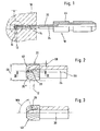
- the reference numeral 10 denotes a rotationally driven, preferably rotationally symmetrical, reworking tool in the embodiment as a deburring tool, with which it is possible to drill holes 12, which open laterally into a substantially cylindrical recess 14 in a workpiece 18, in a particularly economical and reliable manner Deburr their radially inner ends 16.
- the tool can also be static and instead or in addition the workpiece is placed in a rotary motion.
- the tool can also be used for deburring the mouth openings of the recess 14.
- the tool is designed, for example, as a milling, drilling, in particular deep hole drilling, straight-grooved drilling or spiral drilling tool or as a reamer. It is crucial that it has at least one cutting edge 20 * that can perform a machining operation.
- a cutting head 22 which has a plurality of cutting edges 20 *, which extend at least partially in the axial direction, as from the FIGS. 2 and 3 seen.
- the tool has an internal fluid channel 24, from which several embroidery channels 26 originate in the region of the cutting head. These branch channels, are arranged so that they open with mouth openings 28 in the region of the cutting head 22 in the outer peripheral surface. Like from the FIG. 2 it can be seen that the cutting edges are distributed over the entire circumference, so that the mouth openings 28 are at a circumferential distance to at least one cutting edge 20 *, for example the diametrically opposite cutting edge.
- the diameter DS of the cutting head 22 is selected such that it can be introduced into the recess 14 with radial clearance SR.
- the radial clearance is preferably up to a few 1/10 mm and is for example in the range between 0.1 and 5 mm.
- the tool 10 is rotatably and non-displaceably received in a tool holder 30 for the realization of the rotary drive.
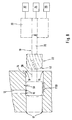
- the tool holder is associated with a rotary drive 32, a feed drive 34 and a fluid pressure source 36.
- the feed and or the rotary drive can also be provided for the workpiece 18.
- an additional rotary drive and / or feed can be provided for the workpiece 18.
- the tool 10 is first moved up to the recess 14 (dash-dotted position shown). Due to the radial clearance SR, the positioning can be relative inaccurate, which allows the use of relatively inaccurate machines.
- the plurality of orifices 28 are distributed so unevenly over the circumference that the sum of the dynamic pressure forces generated in the region of the orifices 28 between the cutting head 22 and the inner wall of the recess 14 can deflect the shaft 20 in the radial direction, so that the resulting dynamic pressure opposite cutting edge touches the burr to be machined at the point 16 and along this cuts or scrapes.
- the tool performs at this moment a rotational movement superimposed circular motion with a radius of the radial clearance SR.
- the branch channels 26 are arranged so that their mouth openings 28 are staggered in the axial direction. But this is not absolutely necessary.
- the embroidery channels 28 have, for example, a diameter or a clear width in the range of 0.1 to 5 mm.
- the mouth openings 28 can lie in the region of a cutting edge 20 * and / or in the region of a groove bottom between two adjacent cutting edges.
- the embroidery channels 26 are formed in a straight line. These channels may be formed by a bore or by an eroded recess.
- the angle WN by which the embroidery channel 26 is inclined to the axis 38 of the tool 10, is preferably in the range of 5 to 175 °, preferably 25 to 155 °, especially preferably between 40 and 50 °. But it can also be used other angles.
- the cutting head 22 has a gate 40, which is preferably formed by a chamfer or a rounding, for example in Kungelform.
- the tool can be made of wear-resistant steel, high-speed steel (HSS, HSSE, HSSEBM), hard metal, ceramic or cermet and provided with a suitable, conventional coating.
- HSS high-speed steel
- HSSE high-speed steel
- HSSEBM hard metal
- ceramic or cermet provided with a suitable, conventional coating.
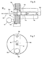
- FIGS. 6 and 7 Reference is made in which a variant of the tool according to Figure 1 to 3 is indicated.
- One in the FIGS. 1 to 3 designated 44 fastening and fixing body, which is integrally formed with the shaft 20 is in the embodiment according to FIG. 6 formed as glued cylindrical sleeve 144. Otherwise, the tool 110 corresponds to the tool 10.
- Those components of the embodiment according to FIG. 6 following the components of the tool Figure 1 to 3 are corresponding, are provided with corresponding reference numerals, which is preceded by a "1":
- the sleeve 144 is made of ordinary steel, which is preferably provided with an anti-corrosion coating. In addition to the bonding, a grub screw, not shown, can be used, which connects the sleeve 144 with the shaft 120 in a form-fitting manner.
- Reference numeral 146 denotes a chamfer, via which the fluid-tight connection to the fluid source takes place.
- the peculiarity of the embodiment according to FIGS. 6 and 7 is that the fluid pressure is used for Vercardund axial position securing the tool in the receptacle 130.
- latch plate 150 in which a keyhole opening 152 is formed.
- the latch plate 150 with operating knob 151 against the force of the spring 148 in FIG. 7 is moved down, the larger circular bore in the locking plate comes to coincide with a cylindrical recess 154 in the tool holder 130, so that the tool can be inserted from the front into the tool holder.
- a shoulder 156 of the sleeve 144 passes behind the sliding plane of the latch plate 150, the latter can slide under the action of the spring 148 upwards until it abuts a pin 158.
- the slot-shaped section of the keyhole opening 152 slides along the outer circumference of the shaft 120. The sleeve 144 is thus trapped behind the latch plate.
- FIGS. 4 and 5 Another modified tool is shown, in which the axial and rotational fixation is carried out in the manner of a bayonet closure. Again, similar reference numerals are used for comparable components, preceded by a "2":
- the shaft 220 carries on the side facing away from the shaping slightly varied cutting head 222 side a fastening and fixing body 244, with which the tool is rotatably and non-displaceably fixed in a tool holder.
- This body has a substantially rectangular shape and cooperates with an undercut not shown in the tool holder, which is constructed in the manner of a bayonet closure.
- the fluid pressure should be raised to relatively high levels to ensure sufficient radial deflection of the tool shank.
- the pressure generating device should be capable of producing a fluid pressure in a range of 30 to 3000 bar. For certain designs of the tool shank and / or the clearance fit between the tool and the receptacle, however, pressures of 3 bar may be sufficient.
- the relative speed between tool and workpiece is in the range between 100 and 50,000 Rpm, the cutting speed being selected in the range between 20 and 300 m / min.
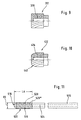
- FIGS. 9 and 10 Further variants of the cutting head 322 and 422 are shown.
- the cross section of the cutting head is almost rectangular, while in the variant of FIG. 10 a clear cut 440 can be seen.
- the orientation of the branch channels 326, 426 is in the FIGS. 9 and 10 modified.
- the cutting head 222 of the variant according to FIG. 4 has the shape of a hemisphere, in which the grooves and cutting edges are incorporated.
- At least the cutting head of the tool or deburring tool is preferably made of a high strength material, e.g. made of tungsten carbide, high-speed steel such as HSS, HSSE or, HSSEBM, ceramic, cermet or another sintered metal material. At least in the region of the most stressed sections, i. be provided in the region of at least one cutting edge 20 * with a coating which is preferably formed as a hard material layer.
- this hard material layer is e.g. Diamond, preferably nanocrystalline diamond in question, titanium-nitride or titanium-aluminum-nitride. Particularly suitable are u.a. a titanium-aluminum-nitride layer and a so-called multilayer coating, which is marketed under the name "Fire I" by Guhring oHG. This is a TiN / (Ti, Al) N multilayer coating.
- a wear protection layer which consists essentially of nitrides with the metal components Cr, Ti and Al and preferably a small proportion of elements for grain refinement, wherein the Cr content at 30 to 65%, preferably 30 to 60%, particularly preferably 40 to 60%, the Al content at 15 to 35%, preferably 17 to 25%, and the Ti content is 16 to 40%, preferably 16 to 35%, particularly preferably 24 to 35%, in each case based on all metal atoms in the entire layer.
- FIGS. 11 to 17 Other embodiments are in the FIGS. 11 to 17 described, for which embodiments, the design principles described above apply in particular with regard to tool holder, material and coating alike.
- FIGS. 11 to 13 and 14 to 17 for elements that correspond to the components of the embodiments described above, associated with similar reference numerals, but which is preceded by a "5" and a "6".
- FIG. 14 shows a substantially cylindrically shaped tool body, which is inserted into a tool holder not shown in detail and with this nadound connected fixedly, for example soldered.
- the tool holder can have any common shape.
- FIG. 14 sits on a cylindrical shaft 520, for example, with a diameter of 1.6 mm Cutting head 522, which has an outer diameter DS of 1.8 mm.
- the tool is then used to deburr a recess or bore that opens into a bore with an inside diameter of 2 mm.
- a centric fluid channel 524 extends through the entire tool body and is sealed at the 570 side of the barrel.
- the cutting head 522 with an axial length LA of, for example, 5 mm is designed as a reaming tool and has a Viekress - namely 14 - of helically extending cutting edges 520 *.
- At a distance of, for example, 3 mm from the cutting head tip there are two mouth openings 528 of branch channels 526, which run in such a way that their axes 527 lie in a common radial plane ER (cf. FIGS. 12 and 13 ).
- the diameter of the branch channels is for example 0.3 mm.
- the central angle WZ which is spanned by the planes containing the center axis 523 of the fluid channel 524 and the axes 527 of the branch channels 526, is less than 180 °, for example about 130 °.
- further branch channels they are preferably distributed such that the central angle WZ between the outermost puncture channels is subdivided by the axis of the further puncture channels extending radial planes through the axis of the fluid channel into equal partial angle.
- the axes 527 of the branch channels 526 are perpendicular to the center leg of the fluid channel.
- the axes 527 to the central axis 523 at an acute angle of, for example, 60 ° inclined in such a way that the mouth openings 528 closer to the top of the Tool are as the points at which the branch channels 526 branch off from the fluid channel 524.
- the mouth openings 528 lie in the circumferential direction offset from the cutting edges 520 *, that is, in a groove bottom between adjacent cutting edges.
- the position of the mouth openings can vary within wide limits.
- the tool after FIGS. 11 to 13 has a cutting edge configuration such that a negative rake angle or reverse rake angle RSW is formed on the cutting edge 520 *.
- the cutting edge 520 * is given a rather scraping function, with the result that it is advantageous for removing a residual chip on the bore 12 to be deburred to keep the radially outward pressure force of the tool against the inner surface of the recess 14 relatively large That is, to increase the fluid pressure or to make the shank of the tool softer or compliant.
- FIGS. 14 to 17 a further variant of a tool according to the invention is shown.
- This deburring tool is different from the tool FIGS. 11 to 13 designed for drilling much larger internal diameter, for example, for a diameter of the recess 14 of 14 mm.
- the cutting head 622 carried by a cylindrical shank 620 for example integrally formed, has an outer diameter DS of 13.75 mm, so that in this case as well, a radial play of at most approximately 0.25 when inserting the tool into the recess 14 remains mm.
- the diameter of the shaft 620 is for example only about 5 mm.
- the shaft is thus significantly tapered with respect to the cutting head 622. With 619 a portion is indicated, via which the shaft 620 can be attached to a tool holder (not shown).
- the cutting head 622 has 16 helically extending cutting edges 620 *, between which as many flutes 631 remain.
- the cutting edge foot diameter FDS is for example about 12 mm.
- a centric fluid channel 624 is provided which is closed in the region of the cutting head 622 by an example soldered body 629 frontally.
- the mouth openings 628 lie in the region of the groove walls 631.
- the diameter of the branch channels is for example about 0.8 mm.
- the branch channels open into pairs in two adjacent grooves, in such a way that the mouth openings of a groove lie on a helix parallel to the groove. But it is - as is clear from the above description - not necessary to concentrate the mouth openings so closely. They can also be distributed over a much larger central angle, with only the criteria of claim 2 must be met.
- the branch channels 626 are inclined with its axis 627 at an acute angle PHI to the central axis 623 of the fluid channel 624.
- this angle is about 60 ° for each stitch channel.
- the cutting edges 620 * are specially designed, in such a way that - as out FIG. 16 seen in detail - at the cutting edge 620 * a positive rake angle or remindspanwinkel RSW arises. This is the embodiment, for example, 3 °.
- the pressure of the cutting head directed radially outwards onto the inner wall of the recess 14 can thus be kept smaller with this tool.
- the mode of action of the tools after the FIGS. 11 to 17 basically corresponds to that of the other described embodiments.
- the deburring process can be optimized by targeted positioning of the central axis 523 or 623 of the tool to the center of the recess 14 into which the tool is inserted , When the center shafts 523, 623 are aligned exactly with the center of the recess, the cutting head will make uniform machining of the inner surface of the recess.
- the cutting head - By targeted eccentric driving of the cutting head, preferably in such a way that the radial eccentric position is matched to the position of the deburring orifice 16, the cutting head - when it is retracted into the recess - can be forced upon pressurization with the fluid, a movement to that leads that the contact pressure of the at least one cutting edge in the region of the embrittlement point 16 to be deburred at the expense of the contact pressure in the remaining area of the inner surface of the Recess 14 is reinforced.
- the deburring function can be made more efficient in this way, in particular when only one to be deburred orifice 16 is present or more orifice points angularly relatively close to each other.
- the deburring of the points 717 of the bore 714 is to be simplified by using a rear gate or rounding transition 741 of the cutting head 722.
- the cutting head 722 itself may be formed in terms of geometry, material and properties in the same way as described above or outlined in the claims, so that thereon will not be discussed here.
- the cutting edges provided for deburring can be formed by a so-called BIAX corrugation 750.
- BIAX corrugation 750 can be formed by a so-called BIAX corrugation 750.
- other geometries of the cutting edges are equally possible.
- the shaft 720 carries at axial distance from the cutting head a guide and support body 752 which has a diameter DF, which is adapted to the inner diameter of the bore 714 in that a function gap 754 of predetermined width is formed.
- This functional gap may vary over the circumference; the decisive factor is the measure in the area of the orifices 728 *.
- the required dynamic pressure can be built up via the orifices 728 * even if the cutting head 722, in which a radial channel system 728, which is indicated by double-dashed dotted lines, has left the bore 714.
- the rounding section 741 can be effectively used for deburring the area 717 when fluid pressure is applied to the inner channel 724, whereby it may be advantageous to subject the tool to a slight axial pull at this moment.
- the controlled radial deflection of the cutting head by a dynamic force namely generates the centrifugal force of an imbalance mass.
- the cutting head 822 can in turn be designed as explained in one of the previously described variants, for example, as in FIG FIG. 18 shown.
- the shaft 820 carries an eccentric ring 860, which is preferably axially and rotationally displaceable on the shaft 820, for example, there by means of a grub screw 862 is clamped.
- the axial adjustment makes it possible to control the size of the dynamic radial force, in particular to adapt to the stability of the shaft.
- the unbalance can for example be integrally integrated into the tool by an asymmetrical bevel is attached.
- the bore 914 to be deburred is a bore of, for example, a diameter of 0.7 mm and a length L of, for example, 6 to 7 mm, which bore adjoins a deep hole bore 970, which likewise has a small diameter DT of for example to 4 mm and a depth TT of, for example, 80 mm.
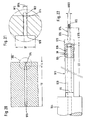
- Fig. 21 the constellation in the area of the bore 914 in the scale M 10: 1 is shown.
- a dotted line indicates the tip region of the deburring tool 910, whose cutting head 922 has been inserted into the bore 914 so far that the exit edge 972 can be deburred.
- the tool 910 is in Fig. 22 shown to scale, in a scale M of about 5: 1.
- a shaft 920 whose length LS corresponds at least to the dimension TT of the bore 970 and whose diameter DS is selected such that the shaft 920 can be received in the bore 970 with a predetermined radial clearance SR, adjoins a clamping section 944.
- the positional relationship between the bore 970 and the tool 910 inserted into the bore for the deburring operation is in Fig. 22 indicated by dash-dotted representation of the bore 970.
- the shaft 920 in turn has an inner bore 924, via which pressure means of the clamping section 944 can be fed.
- a radial passage is designated, the mouth opening of the inner wall of the bore 970 is located at a predetermined distance.
- the shaft 920 carries on the side facing away from the body 944 a so-called Entgratungslanze 974, which carries the actual cutting head 922 at the end of a pin 976.
- the diameter D922 of the cutting head is slightly smaller than the diameter D914 of the bore 914.
- the Entgratungslanze 974 is releasably attached to the tool shaft 920, for example, screwed so that the inner bore 924 is closed.
- the design of the tool according to Fig. 22 allows to use different materials for the sections 944, for the shaft 920 and for the actual trimming lance 974 with cutting head 922. Since the shank 920 has a very large axial length in comparison to its diameter DS, it has proved to be advantageous to produce this shank from a high-strength material whose elasticity is chosen so that the radial deflections occurring during deburring are exclusively in the elastic deformation region of the material lie. Suitable materials are hard materials, such as hard metals or cermets, but also composite materials, such as CFRP composites.
- the shape of the cutting head 922 is not limited to the geometry shown. Rather, all common geometries can be used, wherein the design of the cutting can be varied within wide limits. Depending on the axial length of the bore 914, the length L976 of the pin 976 is selected.
- the tool according to Fig. 22 can of course also by an integrated imbalance in the tool (as in connection with the FIGS. 18 and 19 described) to the movements required for the Entgratungsvorgang be excited.
- a plurality of internal fluid channels may be provided.
- the invention should not be limited to the illustrated embodiments.
- Examples of common and useful designs of the cutting head are the cylindrical shape, flame shape, spherical shape, roll base, ogival shape, pointed cone shape, round arch shape, disc shape and teardrop shape, as for example for tungsten carbide burrs - for example, the company August Rüggeberg GmbH & Co. KG, PFERD tools, 51709 Marienheide - to be used.
- the under relatively high pressure fluid can also be used for deburring, be it by the "water cutting effect", ie by the construction of a cutting jet alone or by the dynamic pressure caused by the radially emerging fluid pressure dynamic pressure, which leads to a radial deflection of the tool shaft and thus the cutting head.
- the invention thus provides a preferably rotationally driven tool for deburring apertures, such as bores, which open laterally into a substantially cylindrical recess.
- the tool has a cutting head which is seated on a shaft and has at least one cutting edge which extends at least in sections in the axial direction.
- a radial force generating device is integrated into the tool, for example in the form of at least one internal fluid channel from the at least one stitch channel emanating in the region of the cutting head preferably at a circumferential distance to the at least one Cutting edge opens into the outer peripheral surface.
- the diameter of the cutting head is selected to be radially insertable into the recess, the radial force generated either upon rotation of the tool or through the supply of pressurized fluid results in the cutting head being deflected radially elastically, thereby causing the cutting head to deflect
- the inner surface of the recess is gently machined while the deburring process can be performed reliably.
Landscapes
- Engineering & Computer Science (AREA)
- Mechanical Engineering (AREA)
- Drilling Tools (AREA)
- Milling, Broaching, Filing, Reaming, And Others (AREA)
Applications Claiming Priority (6)
| Application Number | Priority Date | Filing Date | Title |
|---|---|---|---|
| DE10222155 | 2002-05-17 | ||
| DE10222155 | 2002-05-17 | ||
| DE10248777 | 2002-10-18 | ||
| DE10248777 | 2002-10-18 | ||
| DE10321670A DE10321670A1 (de) | 2002-05-17 | 2003-05-14 | Werkzeug, Vorrichtung und Verfahren zum Entgraten von Bohrungen |
| DE10321670 | 2003-05-14 |
Publications (2)
| Publication Number | Publication Date |
|---|---|
| EP1362659A1 EP1362659A1 (de) | 2003-11-19 |
| EP1362659B1 true EP1362659B1 (de) | 2011-03-23 |
Family
ID=29273277
Family Applications (1)
| Application Number | Title | Priority Date | Filing Date |
|---|---|---|---|
| EP03011272A Expired - Lifetime EP1362659B1 (de) | 2002-05-17 | 2003-05-16 | Werkzeug, Vorrichtung und Verfahren zum Entgraten von Bohrungen |
Country Status (3)
| Country | Link |
|---|---|
| EP (1) | EP1362659B1 (pl) |
| JP (1) | JP2004291224A (pl) |
| PL (1) | PL360223A1 (pl) |
Families Citing this family (13)
| Publication number | Priority date | Publication date | Assignee | Title |
|---|---|---|---|---|
| JP2003340631A (ja) | 2002-05-17 | 2003-12-02 | Guehring Joerg | ボーリング孔のバリを取るための工具、装置、及びその方法 |
| DE102004010372A1 (de) * | 2004-03-03 | 2005-09-22 | Gühring, Jörg, Dr. | Werkzeug zum Entgraten von Bohrungen |
| AT502527B1 (de) * | 2005-09-12 | 2008-08-15 | Tement Franz | Spanabhebendes schaftwerkzeug |
| DE102006006564B4 (de) * | 2006-01-23 | 2022-12-08 | Gühring KG | Werkzeug zum Entgraten von Bohrungen sowie Bausatz für ein solches Werkzeug |
| ITMI20071903A1 (it) | 2007-10-04 | 2009-04-05 | Getters Spa | Metodo per la produzione di pannelli solari mediante l'impiego di un tristrato polimerico comprendente un sistema getter composito |
| JP2010149271A (ja) * | 2008-11-26 | 2010-07-08 | Hitachi Ltd | 角部加工工具 |
| JP5469685B2 (ja) * | 2012-01-06 | 2014-04-16 | 本田技研工業株式会社 | バリ取り方法およびバリ取り機構 |
| JP5862960B2 (ja) * | 2012-12-17 | 2016-02-16 | 株式会社デンソー | 被加工部材のバリ除去方法、およびバリ除去装置 |
| JP2015112690A (ja) * | 2013-12-12 | 2015-06-22 | 自動車部品工業株式会社 | 交差孔のバリ取り装置とこれを用いたバリ取り方法 |
| DE102016205657B4 (de) * | 2016-04-06 | 2021-06-10 | Gühring KG | Spanabhebendes werkzeug zum entgraten von bohrungen |
| CN106695020B (zh) * | 2017-03-21 | 2018-10-30 | 唐山正元管业有限公司 | 小直径焊管内毛刺去除装置 |
| CN116117238B (zh) * | 2022-12-29 | 2025-05-02 | 苏州精锐精密机械有限公司 | 一种硬质零件内腔毛刺去除装置 |
| JP7799869B1 (ja) * | 2025-01-24 | 2026-01-15 | マーレエンジンコンポーネンツジャパン株式会社 | バリ取り刃具、バリ取り装置、研削刃具および研削装置 |
Citations (3)
| Publication number | Priority date | Publication date | Assignee | Title |
|---|---|---|---|---|
| DE1167302B (de) * | 1962-06-21 | 1964-04-09 | Kronprinz Ag | Verfahren und Vorrichtung zum Abstuetzen eines Stahlhalters beim Entfernen des Innengrates laengsnahtgeschweisster Rohre |
| US20020013988A1 (en) * | 2000-06-28 | 2002-02-07 | Michael Kapgan | Burr removal apparatus |
| DE10118596A1 (de) * | 2001-04-12 | 2002-10-17 | Volkswagen Ag | Vorrichtung zur Bearbeitung einer Wandfläche einer Ausnehmung |
Family Cites Families (4)
| Publication number | Priority date | Publication date | Assignee | Title |
|---|---|---|---|---|
| US4563837A (en) * | 1982-06-14 | 1986-01-14 | Tokiwa Seiki Industrial Company, Limited | Ultra-precision grinding machine |
| DE3327409A1 (de) | 1983-07-29 | 1985-02-07 | Hawera Probst Gmbh + Co, 7980 Ravensburg | Bohrwerkzeug zur herstellung von hinterschneidungen in vorgefertigten bohrungen |
| US5238335A (en) * | 1987-06-11 | 1993-08-24 | Toshiba Tungaloy Co., Ltd. | Reamer |
| JPH08318419A (ja) * | 1995-05-23 | 1996-12-03 | Kobe Steel Ltd | エンドミル |
-
2003
- 2003-05-16 EP EP03011272A patent/EP1362659B1/de not_active Expired - Lifetime
- 2003-05-19 PL PL03360223A patent/PL360223A1/pl not_active IP Right Cessation
- 2003-05-19 JP JP2003140328A patent/JP2004291224A/ja active Pending
Patent Citations (3)
| Publication number | Priority date | Publication date | Assignee | Title |
|---|---|---|---|---|
| DE1167302B (de) * | 1962-06-21 | 1964-04-09 | Kronprinz Ag | Verfahren und Vorrichtung zum Abstuetzen eines Stahlhalters beim Entfernen des Innengrates laengsnahtgeschweisster Rohre |
| US20020013988A1 (en) * | 2000-06-28 | 2002-02-07 | Michael Kapgan | Burr removal apparatus |
| DE10118596A1 (de) * | 2001-04-12 | 2002-10-17 | Volkswagen Ag | Vorrichtung zur Bearbeitung einer Wandfläche einer Ausnehmung |
Also Published As
| Publication number | Publication date |
|---|---|
| PL360223A1 (pl) | 2003-12-01 |
| JP2004291224A (ja) | 2004-10-21 |
| EP1362659A1 (de) | 2003-11-19 |
Similar Documents
| Publication | Publication Date | Title |
|---|---|---|
| EP3085481B1 (de) | Bohr-fas-kombi-werkzeug | |
| EP2560778B1 (de) | Bohrkopf für ein tiefbohrwerkzeug zum bta-tiefbohren und tiefbohrwerkzeug | |
| EP2318166B1 (de) | Werkzeug für spanende bearbeitung eines werkstücks | |
| DE3930936C2 (de) | Kombiniertes Bohr-und Reibwerkzeug | |
| EP2635394B1 (de) | Einlippenbohrer | |
| CH678834A5 (pl) | ||
| WO1984001117A1 (fr) | Tete d'alesage et de fraisage et outil d'alesage et de fraisage se fixant a l'interieur de celle-ci; procede d'alesage et de fraisage d'une piece a usiner | |
| DE3124532A1 (de) | Bohrwerkzeug | |
| DE102017112696A1 (de) | Schneidwerkzeug | |
| EP1727639B1 (de) | Werkzeug und verfahren zum entgraten von bohrungen | |
| EP1362659A1 (de) | Werkzeug, Vorrichtung und Verfahren zum Entgraten von Bohrungen | |
| EP0684099B1 (de) | Kombinationswerkzeug | |
| EP3439816B1 (de) | Reibahle | |
| DE10321670A1 (de) | Werkzeug, Vorrichtung und Verfahren zum Entgraten von Bohrungen | |
| DE102010002669A1 (de) | Drehantreibbares spanabhebendes Werkzeug | |
| DE3727103C2 (pl) | ||
| DE20204848U1 (de) | Auswechselbare Bohrerspitze und Bohrwerkzeuganordnung | |
| DE10112165B4 (de) | Stabmesserkopf zum Verzahnen | |
| WO2005089973A1 (de) | Fliessformbohrverfahren mit gleichzeitiger gewindeherstellung und fliessformbohrwerkzeug zur durchführung des verfahrens | |
| EP0123787B1 (de) | Tiefbohrwerkzeug | |
| EP3036058B1 (de) | Vorrichtung und verfahren zum entgraten von rohren | |
| WO2007082530A2 (de) | Werkzeug zum entgraten von bohrungen | |
| DE69901643T2 (de) | Reibahle | |
| DE102004008167A1 (de) | Aufbohrwerkzeug | |
| DE202004009549U1 (de) | Reibwerkzeug |
Legal Events
| Date | Code | Title | Description |
|---|---|---|---|
| PUAI | Public reference made under article 153(3) epc to a published international application that has entered the european phase |
Free format text: ORIGINAL CODE: 0009012 |
|
| AK | Designated contracting states |
Kind code of ref document: A1 Designated state(s): AT BE BG CH CY CZ DE DK EE ES FI FR GB GR HU IE IT LI LU MC NL PT RO SE SI SK TR |
|
| AX | Request for extension of the european patent |
Extension state: AL LT LV MK |
|
| 17P | Request for examination filed |
Effective date: 20040419 |
|
| AKX | Designation fees paid |
Designated state(s): AT BE BG CH CY CZ DE DK EE ES FI FR GB GR HU IE IT LI LU MC NL PT RO SE SI SK TR |
|
| 17Q | First examination report despatched |
Effective date: 20040701 |
|
| 17Q | First examination report despatched |
Effective date: 20040701 |
|
| GRAP | Despatch of communication of intention to grant a patent |
Free format text: ORIGINAL CODE: EPIDOSNIGR1 |
|
| GRAS | Grant fee paid |
Free format text: ORIGINAL CODE: EPIDOSNIGR3 |
|
| GRAA | (expected) grant |
Free format text: ORIGINAL CODE: 0009210 |
|
| AK | Designated contracting states |
Kind code of ref document: B1 Designated state(s): AT BE BG CH CY CZ DE DK EE ES FI FR GB GR HU IE IT LI LU MC NL PT RO SE SI SK TR |
|
| REG | Reference to a national code |
Ref country code: GB Ref legal event code: FG4D Free format text: NOT ENGLISH |
|
| REG | Reference to a national code |
Ref country code: CH Ref legal event code: EP |
|
| REG | Reference to a national code |
Ref country code: IE Ref legal event code: FG4D |
|
| REF | Corresponds to: |
Ref document number: 50313558 Country of ref document: DE Date of ref document: 20110505 Kind code of ref document: P |
|
| REG | Reference to a national code |
Ref country code: DE Ref legal event code: R096 Ref document number: 50313558 Country of ref document: DE Effective date: 20110505 |
|
| REG | Reference to a national code |
Ref country code: NL Ref legal event code: VDEP Effective date: 20110323 |
|
| PG25 | Lapsed in a contracting state [announced via postgrant information from national office to epo] |
Ref country code: GR Free format text: LAPSE BECAUSE OF FAILURE TO SUBMIT A TRANSLATION OF THE DESCRIPTION OR TO PAY THE FEE WITHIN THE PRESCRIBED TIME-LIMIT Effective date: 20110624 Ref country code: SE Free format text: LAPSE BECAUSE OF FAILURE TO SUBMIT A TRANSLATION OF THE DESCRIPTION OR TO PAY THE FEE WITHIN THE PRESCRIBED TIME-LIMIT Effective date: 20110323 |
|
| PG25 | Lapsed in a contracting state [announced via postgrant information from national office to epo] |
Ref country code: CY Free format text: LAPSE BECAUSE OF FAILURE TO SUBMIT A TRANSLATION OF THE DESCRIPTION OR TO PAY THE FEE WITHIN THE PRESCRIBED TIME-LIMIT Effective date: 20110323 Ref country code: FI Free format text: LAPSE BECAUSE OF FAILURE TO SUBMIT A TRANSLATION OF THE DESCRIPTION OR TO PAY THE FEE WITHIN THE PRESCRIBED TIME-LIMIT Effective date: 20110323 Ref country code: BG Free format text: LAPSE BECAUSE OF FAILURE TO SUBMIT A TRANSLATION OF THE DESCRIPTION OR TO PAY THE FEE WITHIN THE PRESCRIBED TIME-LIMIT Effective date: 20110623 Ref country code: SI Free format text: LAPSE BECAUSE OF FAILURE TO SUBMIT A TRANSLATION OF THE DESCRIPTION OR TO PAY THE FEE WITHIN THE PRESCRIBED TIME-LIMIT Effective date: 20110323 |
|
| REG | Reference to a national code |
Ref country code: IE Ref legal event code: FD4D |
|
| PG25 | Lapsed in a contracting state [announced via postgrant information from national office to epo] |
Ref country code: PT Free format text: LAPSE BECAUSE OF FAILURE TO SUBMIT A TRANSLATION OF THE DESCRIPTION OR TO PAY THE FEE WITHIN THE PRESCRIBED TIME-LIMIT Effective date: 20110725 Ref country code: EE Free format text: LAPSE BECAUSE OF FAILURE TO SUBMIT A TRANSLATION OF THE DESCRIPTION OR TO PAY THE FEE WITHIN THE PRESCRIBED TIME-LIMIT Effective date: 20110323 |
|
| BERE | Be: lapsed |
Owner name: GUHRING, JORG, DR. Effective date: 20110531 |
|
| PG25 | Lapsed in a contracting state [announced via postgrant information from national office to epo] |
Ref country code: SK Free format text: LAPSE BECAUSE OF FAILURE TO SUBMIT A TRANSLATION OF THE DESCRIPTION OR TO PAY THE FEE WITHIN THE PRESCRIBED TIME-LIMIT Effective date: 20110323 Ref country code: RO Free format text: LAPSE BECAUSE OF FAILURE TO SUBMIT A TRANSLATION OF THE DESCRIPTION OR TO PAY THE FEE WITHIN THE PRESCRIBED TIME-LIMIT Effective date: 20110323 Ref country code: CZ Free format text: LAPSE BECAUSE OF FAILURE TO SUBMIT A TRANSLATION OF THE DESCRIPTION OR TO PAY THE FEE WITHIN THE PRESCRIBED TIME-LIMIT Effective date: 20110323 Ref country code: ES Free format text: LAPSE BECAUSE OF FAILURE TO SUBMIT A TRANSLATION OF THE DESCRIPTION OR TO PAY THE FEE WITHIN THE PRESCRIBED TIME-LIMIT Effective date: 20110704 |
|
| PG25 | Lapsed in a contracting state [announced via postgrant information from national office to epo] |
Ref country code: MC Free format text: LAPSE BECAUSE OF NON-PAYMENT OF DUE FEES Effective date: 20110531 Ref country code: NL Free format text: LAPSE BECAUSE OF FAILURE TO SUBMIT A TRANSLATION OF THE DESCRIPTION OR TO PAY THE FEE WITHIN THE PRESCRIBED TIME-LIMIT Effective date: 20110323 |
|
| REG | Reference to a national code |
Ref country code: CH Ref legal event code: PL |
|
| PLBE | No opposition filed within time limit |
Free format text: ORIGINAL CODE: 0009261 |
|
| STAA | Information on the status of an ep patent application or granted ep patent |
Free format text: STATUS: NO OPPOSITION FILED WITHIN TIME LIMIT |
|
| PG25 | Lapsed in a contracting state [announced via postgrant information from national office to epo] |
Ref country code: LI Free format text: LAPSE BECAUSE OF NON-PAYMENT OF DUE FEES Effective date: 20110531 Ref country code: CH Free format text: LAPSE BECAUSE OF NON-PAYMENT OF DUE FEES Effective date: 20110531 Ref country code: IE Free format text: LAPSE BECAUSE OF FAILURE TO SUBMIT A TRANSLATION OF THE DESCRIPTION OR TO PAY THE FEE WITHIN THE PRESCRIBED TIME-LIMIT Effective date: 20110323 |
|
| REG | Reference to a national code |
Ref country code: FR Ref legal event code: ST Effective date: 20120131 |
|
| 26N | No opposition filed |
Effective date: 20111227 |
|
| GBPC | Gb: european patent ceased through non-payment of renewal fee |
Effective date: 20110623 |
|
| PG25 | Lapsed in a contracting state [announced via postgrant information from national office to epo] |
Ref country code: DK Free format text: LAPSE BECAUSE OF FAILURE TO SUBMIT A TRANSLATION OF THE DESCRIPTION OR TO PAY THE FEE WITHIN THE PRESCRIBED TIME-LIMIT Effective date: 20110323 |
|
| PG25 | Lapsed in a contracting state [announced via postgrant information from national office to epo] |
Ref country code: BE Free format text: LAPSE BECAUSE OF NON-PAYMENT OF DUE FEES Effective date: 20110531 |
|
| REG | Reference to a national code |
Ref country code: DE Ref legal event code: R097 Ref document number: 50313558 Country of ref document: DE Effective date: 20111227 |
|
| PG25 | Lapsed in a contracting state [announced via postgrant information from national office to epo] |
Ref country code: FR Free format text: LAPSE BECAUSE OF NON-PAYMENT OF DUE FEES Effective date: 20110531 |
|
| PG25 | Lapsed in a contracting state [announced via postgrant information from national office to epo] |
Ref country code: IT Free format text: LAPSE BECAUSE OF FAILURE TO SUBMIT A TRANSLATION OF THE DESCRIPTION OR TO PAY THE FEE WITHIN THE PRESCRIBED TIME-LIMIT Effective date: 20110323 |
|
| PG25 | Lapsed in a contracting state [announced via postgrant information from national office to epo] |
Ref country code: GB Free format text: LAPSE BECAUSE OF NON-PAYMENT OF DUE FEES Effective date: 20110623 |
|
| REG | Reference to a national code |
Ref country code: AT Ref legal event code: MM01 Ref document number: 502713 Country of ref document: AT Kind code of ref document: T Effective date: 20110516 |
|
| PG25 | Lapsed in a contracting state [announced via postgrant information from national office to epo] |
Ref country code: AT Free format text: LAPSE BECAUSE OF NON-PAYMENT OF DUE FEES Effective date: 20110516 |
|
| PG25 | Lapsed in a contracting state [announced via postgrant information from national office to epo] |
Ref country code: LU Free format text: LAPSE BECAUSE OF NON-PAYMENT OF DUE FEES Effective date: 20110516 |
|
| PG25 | Lapsed in a contracting state [announced via postgrant information from national office to epo] |
Ref country code: TR Free format text: LAPSE BECAUSE OF FAILURE TO SUBMIT A TRANSLATION OF THE DESCRIPTION OR TO PAY THE FEE WITHIN THE PRESCRIBED TIME-LIMIT Effective date: 20110323 |
|
| PG25 | Lapsed in a contracting state [announced via postgrant information from national office to epo] |
Ref country code: HU Free format text: LAPSE BECAUSE OF FAILURE TO SUBMIT A TRANSLATION OF THE DESCRIPTION OR TO PAY THE FEE WITHIN THE PRESCRIBED TIME-LIMIT Effective date: 20110323 |
|
| PGFP | Annual fee paid to national office [announced via postgrant information from national office to epo] |
Ref country code: DE Payment date: 20221116 Year of fee payment: 20 |
|
| REG | Reference to a national code |
Ref country code: DE Ref legal event code: R071 Ref document number: 50313558 Country of ref document: DE |