EP1362659B1 - Tool, device and method for deburring bores - Google Patents
Tool, device and method for deburring bores Download PDFInfo
- Publication number
- EP1362659B1 EP1362659B1 EP03011272A EP03011272A EP1362659B1 EP 1362659 B1 EP1362659 B1 EP 1362659B1 EP 03011272 A EP03011272 A EP 03011272A EP 03011272 A EP03011272 A EP 03011272A EP 1362659 B1 EP1362659 B1 EP 1362659B1
- Authority
- EP
- European Patent Office
- Prior art keywords
- tool
- cutting head
- tool according
- cutting
- flow medium
- Prior art date
- Legal status (The legal status is an assumption and is not a legal conclusion. Google has not performed a legal analysis and makes no representation as to the accuracy of the status listed.)
- Expired - Lifetime
Links
Images


Classifications
-
- B—PERFORMING OPERATIONS; TRANSPORTING
- B23—MACHINE TOOLS; METAL-WORKING NOT OTHERWISE PROVIDED FOR
- B23D—PLANING; SLOTTING; SHEARING; BROACHING; SAWING; FILING; SCRAPING; LIKE OPERATIONS FOR WORKING METAL BY REMOVING MATERIAL, NOT OTHERWISE PROVIDED FOR
- B23D77/00—Reaming tools
- B23D77/006—Reaming tools with means for lubricating or cooling
-
- B—PERFORMING OPERATIONS; TRANSPORTING
- B23—MACHINE TOOLS; METAL-WORKING NOT OTHERWISE PROVIDED FOR
- B23B—TURNING; BORING
- B23B51/00—Tools for drilling machines
- B23B51/10—Bits for countersinking
- B23B51/105—Deburring or countersinking of radial holes
-
- B—PERFORMING OPERATIONS; TRANSPORTING
- B23—MACHINE TOOLS; METAL-WORKING NOT OTHERWISE PROVIDED FOR
- B23D—PLANING; SLOTTING; SHEARING; BROACHING; SAWING; FILING; SCRAPING; LIKE OPERATIONS FOR WORKING METAL BY REMOVING MATERIAL, NOT OTHERWISE PROVIDED FOR
- B23D2277/00—Reaming tools
- B23D2277/60—Reaming tools comprising means for lubrication or cooling
Description
Die Erfindung betrifft ein Werkzeug gemäß dem Oberbegriff des Patentanspruchs 1 zum Entgraten von Bohrungen, wie zum Beispiel von Bohrungen, die seitlich in eine beispielsweise zylindrische Ausnehmung münden. Die Erfindung betrifft ferner eine Vorrichtung und ein Verfahren zum Entgraten von derartigen Bohrungen, wobei ein erfindungsgemäßes Werkzeug Anwendung finden soll.The invention relates to a tool according to the preamble of claim 1 for deburring holes, such as bores, which open laterally into an example cylindrical recess. The invention further relates to an apparatus and a method for deburring such holes, wherein a tool according to the invention is to find application.
Das Entgraten von Bohrungen, die seitlich in eine beispielsweise zylindrische Ausnehmung münden, stellt ein großes Problem dar. Derartige Bohrungen sind zum Beispiele auf dem Gebiet der Kraftfahrzeugtechnik - bei Radialbohrungen, die in eine zentrale Axialbohrung der Nockenwelle oder der Kurbelwelle münden - und der Mobilhydraulik dann unumgänglich, wenn es beispielsweise darum geht, einen in einer zentralen Bohrung, aufgenommenen Ventilkolben über Steueranschlüsse in Form von Radialkanälen anzusteuern. Da diese Radialkanäle in der Regel in einem Bohrbearbeitungsgang hergestellt werden müssen, kann selbst bei spezieller Gestaltung des Bohrwerkzeugs nicht zuverlässig ausgeschlossen werden, dass in Bereich, in dem der Radialkanal in die zentrale Bohrungsausnehmung mündet, ein Grat oder ein Restspan verbleibt.The deburring of bores, which open laterally into a cylindrical recess, for example, presents a major problem. Such bores are for example in the field of automotive technology - in radial bores, which open into a central axial bore of the camshaft or crankshaft - and then the mobile hydraulics unavoidable when it comes, for example, to control a valve piston received in a central bore, via control connections in the form of radial channels. Since these radial channels must be made in a Bohrbearbeitungsgang usually, even with a special design of the drilling tool can not be reliably ruled out that in the area in which the radial channel opens into the central bore recess, a burr or a residual chip remains.
Abgesehen davon, dass dieser Span die Strömungsverhältnisse beeinflusst und damit die Justierung und Funktion der entsprechenden hydraulischen Steuerung beeinträchtigt, besteht das besondere Problem, dass ein solcher Span, wenn er nicht vor Inbetriebnahme entfernt wird, nach gewisser Zeit abgerissen wird und im System folgenschwere Schäden verursacht.Apart from the fact that this span influences the flow conditions and thus the Adjustment and function of the corresponding hydraulic control impaired, there is the particular problem that such a chip, if it is not removed before startup, will be demolished after a certain time and causes serious damage in the system.
Man hat daher seit jeher und im Zuge der immer empfindlicher werdenden Steuerungstechnik mit zunehmendem Aufwand versucht, diese Spanreste so vollständig wie möglich von der Radialkanalmündung zu entfernen. Dabei sind speziell gestaltete Werkzeuge zum Einsatz gelangt, mit denen der am Schaft sitzende Schneidkopf möglichst positionsgenau an den zu entfernenden Span herangeführt werden konnte. Die erforderliche große Präzision führt aber dazu, dass sich der Herstellungsprozess wesentlich verteuerte.It has therefore always and in the course of increasingly sensitive control technology with increasing effort to remove this Spanreste as completely as possible from the radial channel mouth. In this case, specially designed tools are used, with which the cutting head sitting on the shaft could be brought as accurately as possible to the chip to be removed. The required high precision, however, means that the manufacturing process has become much more expensive.
Aus dem Dokument
Aus dem Dokument
Diese Aufgabe wird hinsichtlich des Werkzeugs durch die Merkmale des Anspruchs 1, hinsichtlich der Vorrichtung durch die Merkmale des Anspruchs 36 und hinsichtlich des Verfahrens durch die Verfahrensschritte des Anspruchs 42 gelöst.This object is achieved with respect to the tool by the features of claim 1, with respect to the device by the features of
Erfindungsgemäß wird in das aus Schaft und Schneidkopf bestehende Werkzeug eine Radialkraft-Erzeugungseinrichtung integriert, mit der es gelingt, den Schneidkopf eines sehr einfach aufgebauten Werkzeugs, das mit verhältnismäßig geringer Präzision in die Ausnehmung oder Bohrung eingeführt wird, radial auszulenken, so dass der bezüglich des Werkstücks eine Relativ-Drehbewegung ausführende, beispielsweise drehend angetriebene Schneidkopf eine Art "kreisende" bzw. "taumelnde" Schab-oder Schneidbewegung entlang der Innenoberfläche der Ausnehmung oder Bohrung und damit der Mündungsöffnung beispielsweise des Radialkanals ausführt.According to the invention, a radial force generating device is integrated into the tool consisting of shank and cutting head, with which it is possible to deflect the cutting head of a very simply constructed tool, which is introduced with relatively little precision into the recess or bore, so that the respect Workpiece a relative rotary motion exporting, for example, rotationally driven cutting head performs a kind of "circular" or "wobbling" scraping or cutting movement along the inner surface of the recess or bore and thus the mouth opening, for example, the radial channel.
Die Schneide des Werkzeugs bewegt sich dabei bezüglich der Ausnehmung im Werkstück auf einer Zykloide. Es hat sich gezeigt, dass es auf diese Weise gelingt, den Grat bzw. die ggfs. vorhandenen Spanreste schonend und dennoch reproduzierbar und zuverlässig abzutragen, ohne Gefahr zu laufen, dass an anderer Stelle weitere Restspanbildung auftritt.The cutting edge of the tool moves with respect to the recess in the workpiece on a cycloid. It has been found that it succeeds in this way, the burr or the possibly existing Spanreste gently and yet reproducibly and reliably remove, without risk run, that elsewhere further residual chip formation occurs.
Die auf den Schneidkopf einwirkende Radialkraft zu dessen vorzugsweise gesteuerter radialer Auslenkung wird auf zweierlei Art realisiert:
- Eine besonders einfache Konstruktion erhält man dadurch, dass ein in gewöhnlichen Bearbeitungszentren ohnehin vorhandenes unter Druck stehendes Strömungsmittel, wie z.B. ein bei der spanabhebenden Bearbeitung zum Einsatz kommendes Kühl- und Schmiermittel, dazu herangezogen wird, den Schneidkopf radial auszulenken, so dass er die entgratenende Funktion erfüllen.
- A particularly simple construction is obtained by using a fluid under pressure which is present anyway in ordinary machining centers, such as, for example, a coolant and lubricant used during machining, to radially deflect the cutting head so that it performs the deburring function fulfill.
Bei dieser Auslenkung spielen sowohl die durch den Staudruck des Strömungsmittels im Bereich des Schneidkopfs bzw. in dessen näherer Umgebung als auch die durch die Umlenkung der Strömungsmittelströmung hervorgerufenen Impulskräfte eine Rolle, so dass die wirksame Radialkraft gut steuerbar bleibt.In this deflection, both the impulse forces caused by the back pressure of the fluid in the region of the cutting head or in its nearer environment and the deflection caused by the fluid flow play a role, so that the effective radial force remains easily controllable.
Weil die Eingriffsstelle des Werkzeugs dabei ständig mit unter Druck stehendem Strömungsmittel gespült wird, wird der spanabtragende Effekt noch verstärkt. Über den Druck des Strömungsmittels und/oder die Geometrie des Werkzeugschafts lässt sich die radiale Auslenkung des Werkzeugschafts in weiten Grenzen steuern, so dass auch das radiale Spiel des Schneidkopfs in der Ausnehmung verhältnismäßig grob vorgegeben werden kann. Dadurch wird das Werkzeug billiger. Aber auch die Steuerung der Antriebsvorrichtung, in der das Werkzeug aufgenommen wird, lässt sich dadurch stark vereinfachen, da das Werkzeug verhältnismäßig grob zur Achse der Ausnehmung positioniert werden kann. Das Werkzeug kann dadurch auch in relativ ungenau arbeitende Maschinen eingespannt werden. Es positioniert sich mit seiner am Innenumfang der Ausnehmung schabenden Bewegung selbst. Es wurde festgestellt, dass das erfindungsgemäße Arbeitsprinzip für alle gängigen Werkstoffe, d.h. für Stahl, Grauguss bis hin zu Kunststoffen anwendbar ist.Because the point of action of the tool is constantly flushed with pressurized fluid, the chip-removing effect is enhanced. About the pressure of the fluid and / or the geometry of the tool shaft, the radial deflection of the tool shank can be controlled within wide limits, so that the radial clearance of the cutting head in the recess can be given relatively coarse. This makes the tool cheaper. But also the control of the drive device, in which the tool is received, can be greatly simplified, since the tool can be positioned relatively coarse to the axis of the recess. The tool can also do this be clamped in relatively inaccurately working machines. It positions itself with its scraping on the inner circumference of the recess movement itself. It has been found that the working principle of the invention for all common materials, ie for steel, gray cast iron to plastics is applicable.
Grundsätzlich genügt ein einziger Stichkanal, um im Bereich zwischen seiner Mündungsöffnung und der Innenwandung der Ausnehmung eine Druckkraft aufzubauen, die das Werkzeug ausreichend radial auslenkt, damit die Schneidkante wirksam in Eingriff gelangt. Dabei hat sich weiter gezeigt, dass es sogar möglich ist, den Druck des Strömungsmittels derart an den Durchmesser des Stickkanals abzustimmen, dass aus dem Stickkanal ein Strömungsmittelstrahl austritt, der die Funktion eines Schneidstrahls hat, wie er vom sogenannten "Wasserschneiden" her bekannt ist, d.h. mit dem eine spanabhebende Bearbeitung vorgenommen werden kann. Mit anderen Worten, der aus der Mündungsöffnung austretende Strahl kann unabhängig von der Auslenkfunktion für den Werkzeugschaft zum Entgraten herangezogen werden, und zwar schon dann, wenn Schmiermitteldrücke im heutzutage üblichen Bereich von 30 bar aufwärts angewendet werden.In principle, a single branch channel is sufficient to build up a pressure force in the area between its mouth opening and the inner wall of the recess, which deflects the tool sufficiently radially so that the cutting edge effectively engages. It has further been shown that it is even possible to match the pressure of the fluid to the diameter of the embroidery channel in such a way that a fluid jet emerges from the embroidery channel and has the function of a cutting jet, as is known from so-called "water cutting". ie with which a machining can be made. In other words, the jet emerging from the orifice can be used for deburring, regardless of the deflection function for the tool shank, even when lubricant pressures are applied in the usual range of 30 bar upwards.
Gemäß einer weiteren Alternative wird die in das Werkzeug integrierte Radialkraft-Erzeugungseinrichtung von einer Unwuchtmasse gebildet, so dass die Unwucht des Werkzeugs, nämlich vorzugsweise die Unwucht im Bereich oder in der Nähe des Schneidkopfs zur gesteuerten radialen Auslenkung des Schneidkopfs herangezogen werden kann. Über die drehzahl lässt sich auf einfache Weise das Absolutmaß der radialen Auslenkung steuern, wodurch es möglich wird, den Schneidkopf beispielsweise bei relativ kleiner Drehzahl in die Ausnehmung oder Bohrung einzuführen und anschließend die Drehzahl ausreichend weit an zu heben, damit die gewünschte Entgratbewegung der zumindest einen Werkzeugschneide hervorgerufen wird.According to a further alternative, the radial force generating device integrated in the tool is formed by an imbalance mass, so that the imbalance of the tool, namely preferably the unbalance in the region or in the vicinity of the cutting head for controlled radial deflection of the cutting head can be used. About the speed can be easily control the absolute extent of the radial deflection, making it possible to introduce the cutting head, for example, at a relatively low speed in the recess or bore and then raise the speed sufficiently far, so that the desired deburring of the at least one tool cutting edge is caused.
Eine besonders effektive Art der Bearbeitung ergibt sich mit der Weiterbildung des Anspruchs 4. Denn über die Vielzahl der Stichkanäle lässt sich eine wirkungsvollere und schnellere Bearbeitung vornehmen. Diese Modifikation erlaubt ferner die Anbringung mehrerer Schneidkanten am Schneidkopf, so dass die erforderliche Bearbeitungszeit weiter herabgesetzt werden kann.A particularly effective type of processing results with the development of claim 4. Because of the variety of branch channels can make a more effective and faster processing. This modification also allows the attachment of multiple cutting edges on the cutting head, so that the required processing time can be further reduced.
Wenn mehrere Stichkanäle vorgesehen sind, deren Mündungsöffnungen in axialer Richtung gestaffelt sind, kann der oben angesprochene "Schneidstrahleffekt" über eine vergrößerte axiale Länge genutzt werden, was der Reduzierung der Bearbeitungsdauer weiter förderlich ist.If a plurality of branch channels are provided, the mouth openings are staggered in the axial direction, the above-mentioned "cutting beam effect" over an increased axial length can be used, which is the reduction of the processing time further beneficial.
Es hat sich gezeigt, dass besonders vorteilhafte Ergebnisse mit Abmessungen des Stichkanals gemäß Anspruch 6 erzielt werden können, d.h. wenn der Durchmesser der stichkanäle im Bereich von 0,1 bis 5 mm liegt.It has been found that particularly advantageous results can be achieved with dimensions of the branch channel according to claim 6, i. if the diameter of the groove channels is in the range of 0.1 to 5 mm.
Über die Länge des Schafts lässt sich die radiale Flexibilität des Werkzeugs leicht steuern, wobei sich der vorteilhafte Nebeneffekt ergibt, dass ein langer Schaft dazu führt, dass das Werkzeug universeller eingesetzt werden kann, d.h. zum Entgraten von Bohrungen, die verhältnismäßig weit im Inneren der Ausnehmung münden. Das Einsatzgebiet liegt vorzugsweise bei Schaftlängen im Bereich von 5 bis 1000 mm.Over the length of the shaft, the radial flexibility of the tool is easily controlled, with the advantageous side effect that a long shaft makes the tool more universally usable, i. For deburring holes that open relatively far inside the recess. The field of application is preferably at shaft lengths in the range of 5 to 1000 mm.
Wenn, entsprechend Anspruch 7, mehrere innenliegende Strömungsmittelkanäle vorgesehen sind, ergeben sich mehr Möglichkeiten der Anordnung der Mündungsöffnungen an der Außenumfangsfläche des Schneidkopfs.If, according to claim 7, a plurality of internal fluid channels are provided, there are more possibilities of arrangement of the orifices on the outer peripheral surface of the cutting head.
Die Mündungsöffnungen können im Bereich einer Schneidkante liegen, so dass der Raum zwischen Mündungsöffnung und Innenwandung der Ausnehmung so klein wie möglich wird. Es zeigt sich aber, dass die Mündungsöffnungen auch im Bereich eines Nutgrundes zwischen zwei benachbarten Schneidkanten liegen kann, wenn der Strömungsmitteldruck ausreichend hoch gewählt wird, um eine genügend große Staudruckkraft zu erzeugen.The mouth openings can lie in the region of a cutting edge, so that the space between the mouth opening and the inner wall of the recess is as small as possible. It turns out, however, that the mouth openings can also lie in the region of a groove base between two adjacent cutting edges, if the fluid pressure is chosen to be high enough to produce a sufficiently large dynamic pressure force.
Der Stichkanal kann grundsätzlich beliebig ausgerichtet sein und auch gekrümmt, beispielsweise wendelförmig verlaufen. Vorzugsweise wird der zumindest eine Stickkanal geradlinig ausgebildet, wobei er entweder von einer Bohrung oder von einer erodierten Ausnehmung gebildet sein kann. Im letzteren Fall verbleibt eine größere Flexibilität bei der Gestaltung des Kanalquerschnitts.The puncture channel can basically be arbitrarily aligned and also curved, for example helical. Preferably, the at least one embroidery channel is formed in a straight line, wherein it may be formed either by a bore or by an eroded recess. In the latter case, greater flexibility remains in the design of the channel cross-section.
Wenn der Winkel des Stickkanals zur Achse des Werkzeugs im Bereich von 5 bis 175, bevorzugt zwischen 25 bis 155 °, besonders vorzugsweise zwischen 40 und 50 ° gewählt wird, bleiben die Strömungsverluste beherrschbar.If the angle of the embroidery channel to the axis of the tool in the range of 5 to 175, preferably between 25 to 155 °, particularly preferably selected between 40 and 50 °, the flow losses remain manageable.
Wenn die zumindest eine Schneidkante zu einer Axialebene des Werkzeugs unter einem Winkel angestellt ist, kann auf die Schnittbedingungen beim Entgraten gezielt Einfluss genommen werden, wodurch die Arbeitsgenauigkeit verbessert wird.If the at least one cutting edge is set at an angle to an axial plane of the tool, it is possible to influence the cutting conditions during deburring in a targeted manner, thereby improving the working accuracy.
Gute Ergebnisse konnten mit einem radialen Spiel zwischen Schneidkopf und Innenwandung der Ausnehmung im Bereich zwischen 0,1 und 0,5 mm erzielt werden, wobei dieses Spiel an die Höhe des Arbeitsdrucks des Strömungsmittels gekoppelt ist. Es können auch Werte für das Spile bis 5 mm beherrscht werden.Good results could be achieved with a radial clearance between the cutting head and the inner wall of the recess in the range between 0.1 and 0.5 mm, this game is coupled to the height of the working pressure of the fluid. It is also possible to control values for the spile up to 5 mm.
Eine weitere Möglichkeit der Beeinflussung der radialen Auslenkung besteht in der Optimierung der Geometrie des Werkzeug-Schafts. Mit der Weiterbildung nach Anspruch 23 lässt sich die erforderliche radiale Flexibilität des Schafts weiter verbessern.Another way of influencing the radial deflection is to optimize the geometry of the tool shaft. With the development according to claim 23, the required radial flexibility of the shaft can be further improved.
Mit der Weiterbildung des Anspruchs 24 wird das Einführen des Werkzeugs weiter vereinfacht. Wenn eine Art Anschnitt auf beiden Seiten des Schneidkopfs ausgebildet ist, kann das Werkzeug auch zum Entgraten des inneninliegenden Austritts einer Bohrung genutzt werden, in die das Werkzeug eingeführt wird. Die Taumelbewegung des Schneidkopfs schabt dabei wiederum allmählich den Bohrungsgrat ab, und zwar mit der dem Schaft zugewandten Rundung des Schneidkopfs.With the development of
Für die Materialwahl des Werkzeugs gibt es praktisch keine Einschränkungen. Das Werkzeug kann entweder insgesamt oder aber zumindest im Bereich des Schneidkopfs aus einem hochfesten Werkstoff, wie z.B. verschleißfesten Stahl, Schnellstahl (HSS, HSSE, HSSEBM), Hartmetall, Keramok oder Cermet hergestellt sein, wobei auch geeignete Beschichtungen, insbesondere in der Ausgestaltung nach den Ansprüchen 34 bis 36 Anwendung finden können.For the choice of material of the tool there are practically no restrictions. The tool may be made of a high strength material, such as all or at least in the region of the cutting head. wear-resistant steel, high-speed steel (HSS, HSSE, HSSEBM), hard metal, Keramok or cermet be made, with suitable coatings, in particular in the embodiment according to
Mit der Weiterbildung nach Anspruch 27 wird das Werkzeug zu einer leicht handhabbaren Einheit, die in gängige Werkzeugaufnahmen einsetzbar ist.With the development according to claim 27, the tool becomes an easy to handle unit that can be used in common tool holders.
Gemäß Anspruch 12 ergibt sich der besondere Vorteil, dass im Werkzeug mit einfachen Mitteln die Schnittstelle zum Strömungsmittelanschluss hergestellt ist.According to claim 12 there is the particular advantage that the interface is made to the fluid connection in the tool with simple means.
Eine besonders einfache und kostengünstige Variante ist Gegenstand des Anspruchs 13, wonach der Befestigungs- und Fixierungskörper gleichzeitig den Körper zur Einspeisung des Strömungsmittels bildet. Dieser Körper hat vorzugsweise die Gestalt eines einfachen länglichen Hohlzylinders, der mit dem Schaft des Werkzeugs sogar verklebt werden kann. Mit einer geeigneten korrosionsbeständigen Beschichtung versehen, kann dieser Körper aus gewöhnlichem Stahl hergestellt werden, weil die Fixierung in der Werkzeugaufnahme dadurch erfolgen kann, dass der zylindrische Körper mittels des auf der Rückseite einwirkenden Strömungsmitteldrucks gegen eine Schulterfläche in der Werkzeugaufnahme gedrückt wird.A particularly simple and cost-effective variant is the subject of claim 13, according to which the fixing and fixing body simultaneously forms the body for feeding the fluid. This body preferably has the shape of a simple elongated hollow cylinder, which can even be glued to the shank of the tool. Provided with a suitable corrosion-resistant coating, this body can be made of ordinary steel, because the fixation in the tool holder can be effected by pressing the cylindrical body against a shoulder surface in the tool holder by means of the fluid pressure acting on the rear side.
Das Werkzeug kann als Fräs-, Bohr-, insbesondere Tieflochbohr-, geradegenutetes Bohr- oder Spiralbohrwerkzeug oder als Reibahle ausgebildet werden.The tool can be designed as a milling, drilling, in particular deep hole drilling, straight-grooved drilling or spiral drilling tool or as a reamer.
Wenn der Spanwinkel bzw.- bei der Ausbildung als Fräs-oder Reibwerkzeug - der Rückspanwinkel positiv, beispielsweise in einem Größenbereich von 0 bis 10°, vorzugsweise bis 5° gehalten wird, kann die Schneidkante die spanabhebende Wirkung bereits bei relativ geringen Radial-Druckkräften entfalten, so dass der Strömungsmitteldruck kleiner gehalten werden kann.If the rake angle or, in the case of the design as a milling or reaming tool, the back rake angle is kept positive, for example in a size range from 0 to 10 °, preferably to 5 °, the cutting edge can already develop the cutting effect at relatively low radial compressive forces so that the fluid pressure can be kept smaller.
Mit der Ausgestaltung nach Anspruch 30 ergibt sich eine eher schabende Wirkung der zumindest einen Schneidkante. Die Schneidkanten erhalten eher das Profil einer Feile, mit der Folge, dass mit einem im Vergleich zur Ausführung nach Anspruch 29 höheren Strömungsmitteldruck gearbeitet werden sollte.With the embodiment according to claim 30 results in a rather scraping effect of at least one cutting edge. The cutting edges are more like the profile of a file, with the result that you should work with a higher compared to the embodiment of claim 29 fluid pressure.
Wenn mehrere Mündungsöffnungen vorgesehen sind, so liegen diese vorzugsweise - nach Anspruch 14 - in einem Umfangsbereich, der von einem Zentriwinkel bis zu 180°, vorzugsweise bis zu 120° begrenzt wird. Es ist in diesem Fall von Vorteil, die Mündungsöffnungen über diesen Winkelbereich gleichmäßig zu verteilen. Wenn beispielsweise 2 Mündungsöffungen oder 2 Reihen von Mündungsöffnungen vorhanden sind, beträgt der Winkelabstand der Mündungsöffungen bzw. der Mündungsöffung-Reihen 120°. Bei drei Mündungsöffungen ist der Wnkelabstand auf 60° verkleinert, bei 4 Mündungsöffungen auf 40° und bei 5 Mündungsöffungen auf 30°.If more orifices are provided, they are preferably - according to claim 14 - in one Peripheral area, which is limited by a central angle up to 180 °, preferably up to 120 °. It is advantageous in this case to evenly distribute the orifices over this angular range. For example, if there are 2 orifices or 2 rows of orifices, the angular distance of the orifices or ports is 120 °. With three orifice openings, the distance between them is reduced to 60 °, with 4 orifice openings to 40 ° and with 5 orifice openings to 30 °.
Wenn die zumindest eine Schneidkante im Wesentlichen wendelförmig verläuft, ergibt sich eine für das Entfernen des Gratspans besonders günstige Schneidengestaltung. In diesem Fall ist es von Vorteil, bei mehreren Mündungsöffnungen, diese ebenfalls auf einer im Wesentlichen wendelförmigen Linie bzw. - wenn man eine Verjüngung des Schneidkopfs in axialer Richtung berücksichtigt - spiralförmigen Linie anzuordnen.If the at least one cutting edge is substantially helical, the result is a particularly advantageous cutting edge design for removing the burr chip. In this case, it is advantageous for several orifices, this also on a substantially helical line or - if one considers a taper of the cutting head in the axial direction - to arrange a spiral line.
Die Weiterbildung des Werkzeugs gemäß Anspruch 32 hat insbesondere dann Vorteile, wenn der Schaft des Werkzeugs extrem dünn ausgeführt ist, beispielsweise für den Fall, dass der Entgratungsvorgang im Bereich einer Bohrung durchgeführt werden soll, die einen Durchmesser von unter 1 mm hat und sich an eine verhältnismäßig tiefe Bohrung ebenfalls kleinen Durchmessers - von beispielsweise bis zu etwa 4 mm anschließt. Die Materialwahl stellt sicher, dass das Werkzeug auch mit einer derart dünnen Schaftgestaltung ausreichend stabil bleibt, um den Schneidkopf auch nach wiederholter Benutzung exakt zu zentrieren. Die Bearbeitungsgenauigkeit wird dadurch besonders gut steuerbar. Der Schneidjopf selbst kann dann aus anderen Materialien gefertigt und beispielsweise lösbar am Schaft des Werkzeugs befestigt sein.The development of the tool according to
Eine vorteilhafte Ausgestaltung der Vorrichtung zum Entgraten von Bohrungen, die seitlich in eine im wesentlichen zylindrische Ausnehmung münden, ist Gegenstand des Anspruchs 36. Die Drehantriebsvorrichtung kann von einer einfachen Dreh- oder Bohrmaschine oder einem Roboter gebildet sein. In beiden Fällen genügen verhältnismäßig ungenau arbeitende Maschinen.An advantageous embodiment of the device for deburring holes that open laterally into a substantially cylindrical recess is the subject of
Es hat sich gezeigt, dass das Strömungsmittel selbst von einem gasförmigen Medium, wie z.B. Luft gebildet sein kann, um die erforderlichen Kräfte zur Auslenkung des Werkzeugschafts zu erzeugen. Selbstverständlich können alle gängigen Kühl- und Schmiermittel zum Einsatz kommen, auch solche der Mindermengenschmierung.It has been found that the fluid itself can be separated from a gaseous medium, e.g. Air may be formed to produce the forces required to deflect the tool shank. Of course, all common coolants and lubricants can be used, even those of minimum quantity lubrication.
Vorzugsweise arbeitet die Vorrichtung mit einem Strömungsmitteldruck in einem Bereich von 3 bis 3000 bar.Preferably, the device operates at a fluid pressure in a range of 3 to 3000 bar.
Wenn das Werkzeug einen Befestigungs- und Fixierungskörper gemäß Anspruch 27 hat, ist es vorteilhaft, wenn dieser nach Art eines Bajonettverschlusses in der Werkzeugaufnahme aufgenommen ist.If the tool has a fastening and fixing body according to claim 27, it is advantageous if it is accommodated in the manner of a bayonet closure in the tool holder.
Ein besonderer Aspekt der vorliegenden Erfindung besteht darin, dass der - verhältnismäßig hohe - Strömungsmitteldruck - gemäß Anspruch 39 - dazu herangezogen wird, das Werkzeug in der Werkzeugaufnahme axial und in Umfangsrichtung zu fixieren. Es hat sich nämlich gezeigt, dass die Schnittkräfte beim Entgraten mit Leichtigkeit durch die Reibkraft aufgenommen werden kann, die entsteht, wenn der Befestigungs- und Fixierungskörper vom Strömungsmitteldruck gegen eine Halteschulter gedrückt wird. Dies wird dadurch noch erleichtert, dass der Befestigungs- und Fixierungskörper einen größeren Durchmesser als der Schneidkopf erhalten kann.A particular aspect of the present invention is that the - relatively high - fluid pressure - according to claim 39 - is used to fix the tool in the tool holder axially and in the circumferential direction. It has been found that the cutting forces during deburring can be easily absorbed by the frictional force that arises when the fastening and fixing body is pressed by the fluid pressure against a retaining shoulder. This is made even easier by the fact that the fastening and fixing body can get a larger diameter than the cutting head.
Mit der Weiterbildung nach Anspruch 41 ergibt sich eine mit einfachen Bauelementen eine wirksame Schnell-Spannvorrichtung für das Werkzeug.With the development according to claim 41 results in a simple components with an effective quick-clamping device for the tool.
Die wesentlichen Elemente des erfindungsgemäßen Verfahrens zum Entgraten von Bohrungen, beispielsweise von Bohrungen, die seitlich in eine im wesentlichen zylindrische Ausnehmung münden, sind Gegenstand des Anspruchs 42. Das Grundprinzip besteht darin, dass der Strömungsmitteldruck des durch das in die Ausnehmung eingeführten Werkzeugs dazu genutzt wird, den Schneidkopf radial auszulenken und dadurch die zumindest eine Schneidkante in Eingriff mit dem zu entfernenden Span gelangen zu lassen.The essential elements of the method according to the invention for deburring bores, for example boreholes which open laterally into a substantially cylindrical recess, are the subject matter of claim 42. The basic principle is that the fluid pressure of the tool introduced into the recess is used for this purpose to radially deflect the cutting head and thereby allow the at least one cutting edge to engage the chip to be removed.
Weitere vorteilhafte Ausgestaltungen sind Gegenstand der übrigen Unteransprüche.Further advantageous embodiments are the subject of the remaining dependent claims.
Zwar ist es aus dem Dokument
Nachstehend werden anhand schematischer Zeichnungen mehrere Ausführungsbeispiele der Erfindung näher erläutert. Es zeigen:
-
Figur 1 eine schematische Seitenansicht eines erfindungsgemäßen Werkzeugs nach einer ersten Ausführungsform; -
Figur 2 die Einzelheit "II" inFigur 1 ; -
Figur 3 einen schematischen Schnitt III-III inFigur 2 ; -
Figur 4 eine schematische Seitenansicht einer weiteren Ausführungsform des erfindungsgemäßen Werkzeugs; -
Figur 5 die Ansicht "V" inFigur 4 ; -
Figur 6 eine schematische Teil-Ansicht einer Variante des Werkzeugs nachFigur 1 mit angedeuteter Aufnahme und Fixierung in einer Werkzeugaufnahme; -
Figur 7 die Ansicht "VII" inFigur 6 ; -
Figur 8 eine schematische Darstellung der Positionen des erfindungsgemäßen Werkzeugs vor und während des Bearbeitungseingriffs; -
Figur 9 und 10 Varianten der Gestaltung des Schneidkopfs; -
Figur 11 in stark vergrößerter Darstellung die schematische Seitenansicht einer weiteren Ausführungsform des Entgratwerkzeugs; -
Figur 12Figur 11 ; -
Figur 13 in vergrößerter Darstellung den Schnitt gemäß XIII-XIII inFigur 12 -
Figur 14 -
Figur 15 in vergrößerter Darstellung den Schneidkopf des Werkzeugs nachFigur 14 ; -
Figur 16Figur 15 ; -
Figur 17 eine schematische Schnittansicht des Schneidkopfs nachFigur 15 zur Veranschaulichung der Lage der darin vorgesehenen Stichkanäle; -
Figur 18Figur 8 ähnlichen Darstellung eine schematische Ansicht einer weiteren Ausführungsform der Erfindung; -
Figur 19Figur 18 ähnliche Darstellung einer weiteren Ausführungsform der Erfindung; -
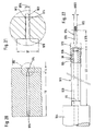
Figur 20 -
Figur 21 die Darstellung der Einzelheit "XXI" inFigur 20 -
Figur 22Figur 21 etwas verkleinertem Maßstab die Ansicht eines Werkzeugs, mit dem dieBearbeitungsaufgabe gemaäß Figur 20, 21 gelöst werden kann.
-
FIG. 1 a schematic side view of a tool according to the invention according to a first embodiment; -
FIG. 2 the detail "II" inFIG. 1 ; -
FIG. 3 a schematic section III-III inFIG. 2 ; -
FIG. 4 a schematic side view of another embodiment of the tool according to the invention; -
FIG. 5 the view "V" inFIG. 4 ; -
FIG. 6 a schematic partial view of a variant of the tool according toFIG. 1 with suggested inclusion and fixation in a tool holder; -
FIG. 7 the view "VII" inFIG. 6 ; -
FIG. 8 a schematic representation of the positions of the tool according to the invention before and during the machining engagement; -
FIGS. 9 and 10 Variants of the design of the cutting head; -
FIG. 11 in a greatly enlarged view, the schematic side view of another embodiment of the deburring tool; -
FIG. 12 in a slightly enlarged view of the cutting head of the toolFIG. 11 ; -
FIG. 13 in an enlarged view the section according to XIII-XIII inFIG. 12 ; -
FIG. 14 on a somewhat enlarged scale, the schematic side view of another embodiment of the deburring tool; -
FIG. 15 in an enlarged view of the cutting head of the toolFIG. 14 ; -
FIG. 16 a partial sectional view according to XVI-XVI inFIG. 15 ; -
FIG. 17 a schematic sectional view of the cutting head afterFIG. 15 to illustrate the location of the branch channels provided therein; -
FIG. 18 in one of theFIG. 8 similar representation of a schematic view of another embodiment of the invention; -
FIG. 19 one of theFIG. 18 similar representation of another embodiment of the invention; -
FIG. 20 the schematic view of a hole to be deburred with a specially designed tool according to the invention in particularly inaccessible places; -
FIG. 21 the representation of the detail "XXI" inFIG. 20 ; and -
FIG. 22 in one compared toFIG. 21 on a slightly reduced scale, the view of a tool with which the machining task correspondsFIG. 20, 21 can be solved.
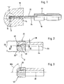
In
Das Werkzeug ist beispielsweise als Fräs-, Bohr-, insbesondere Tieflochbohr-, geradegenutetes Bohr- oder Spiralbohrwerkzeug oder als Reibahle ausgebildet. Entscheidend ist, dass es zumindest eine Schneidkante 20* hat, die eine spanabhebende Bearbeitung durchführen kann.The tool is designed, for example, as a milling, drilling, in particular deep hole drilling, straight-grooved drilling or spiral drilling tool or as a reamer. It is crucial that it has at least one
Bei dem Werkzeug sitzt an einem Schaft 20 ein Schneidkopf 22, der eine Vielzahl von Schneidkanten 20* hat, die sich zumindest abschnittsweise in axialer Richtung erstrecken, wie aus den
Das Werkzeug hat einen innenliegenden Strömungsmittelkanal 24, von dem im Bereich des Schneidkopfs mehrere Stickkanäle 26 ausgehen. Diese Stichkanäle, sind so angeordnet, dass sie mit Mündungsöfnungen 28 im Bereich des Schneidkopfs 22 in dessen äußere Umfangsfläche münden. Wie aus der
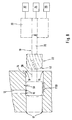
Mit diesem Aufbau des Werkzeugs lässt sich folgendes Arbeitsprinzip mit den nachfolgend anhand der
Das Werkzeug 10 ist zur Realisierung des Drehantriebs in einer Werkzeugaufnahme 30 dreh- und verschiebefest aufgenommen. Der Werkzeugaufnahme ist ein Drehantrieb 32, ein Vorschubantrieb 34 und eine Strömungsmitteldruckquelle 36 zugeordnet. Der Vorschub und oder der Drehantrieb kann auch für das Werkstück 18 vorgesehen sein. Für das Werkstück 18 kann auch ein zusätzlicher Drehantrieb und/oder Vorschub vorgesehen sein.The
Wenn die Radialbohrung 12 im radial inneren Mündungsbereich entgratet werden soll, wird das Werkzeug 10 zunächst an die Ausnehmung 14 herangefahren (strichpunktiert dargestellte Stellung). Aufgrund des radialen Spiels SR kann die Positionierung relativ ungenau erfolgen, was den Einsatz von relativ ungenauen Maschinen erlaubt.If the radial bore 12 is to be deburred in the radially inner mouth region, the
Anschließend wird der Drehantrieb und der Vorschub betätigt, so dass das Werkzeug in die Ausnehmung so weit eingefahren wird (oder eine entsprechende kinematisch umgekehrte Bewegung), dass die Mündungsstelle 16 erreicht wird. Spätestens dann, wenn die vorderste Schneidkante 20* diese Stelle erreicht (strich-zwei-punktiert dargestellte Lage), wird Strömungsmittel, beispielsweise Wasser oder ein anderes Werkzeug-Kühl- und Schmiermittel, oder aber auch ein gasförmiges Stzrömungsmittel unter verhältnismäßig hohem Druck von 3 bis 3000 bar in den innenliegenden Strömungsmittelkanal 24 eingespeist. Im Bereich der Mündungsöffnungen 28 baut sich somit im Zusammenwirken mit der inneren Umfangswandung der Ausnehmung 14 ein entsprechend großer Staudruck auf, der durch die kleinen Pfeile in
Die Vielzahl von Mündungsöffnungen 28 sind über den Umfang derart ungleichmäßig verteilt sind, dass die Summe der im Bereich der Mündungsöffnungen 28 zwischen dem Schneidkopf 22 und der Innenwandung der Ausnehmung 14 erzeugten Staudruckkräfte den Schaft 20 in radialer Richtung auslenken können, so dass die der resultierenden Staudruckkraft gegenüberliegende Schneidkante den zu bearbeitenden Grat an der Stelle 16 berührt und an diesem entlang schneidet bzw. schabt. Mit anderen Worten, das Werkzeug führt in diesem Moment eine der Drehbewegung überlagerte Kreisbewegung mit einem Radius des radialen Spiels SR aus.The plurality of
Jedesmal, wenn eine Mündungsöffnung 28 die Radialbohrung 12 erreicht und überstreicht, baut sich darüber hinaus ein energiereicher Schneidstrahl auf, der zu einer zusätzlichen spanabhebenden Bearbeitung der kritischen Stelle 16 führt. Der Entgratvorgang wird damit sehr wirkungsvoll durchgeführt.Each time an
Wie sich aus den
Die Stickkanäle 28 haben beispielsweise einen Durchmesser bzw. eine lichte Weite im Bereich von 0,1 bis 5 mm.The
Aus der vorstehenden Beschreibung wird klar, dass die Staudruckkräfte bei den angegebenen Drücken des Strömungsmittels groß genug sind, den flexiblen Schaft 20 ausreichend weit auszulenken. Über die Länge des Schafts, die im Bereich von 5 bis 1000 mm liegen kann, lässt sich die elastische Verformung steuern. Die Figur zeigt, dass der Schaft 20 im Verhältnis zum Durchmesser DS des Schneidkopfs 22 verjüngt ist.It will be understood from the foregoing description that the back pressure forces at the indicated pressures of the fluid are great enough to deflect the
Die Mündungsöffnungen 28 können im Bereich einer Schneidkante 20* und/oder im Bereich eines Nutgrundes zwischen zwei benachbarten Schneidkanten liegen.The
Aus der
Der Winkel WN, um den der Stickkanal 26 zur Achse 38 des Werkzeugs 10 geneigt ist, liegt vorzugsweise im Bereich von 5 bis 175 °, vorzugsweise von 25 bis 155 °, besonders bevorzugt zwischen 40 und 50 °. Es können aber auch andere Winkel verwendet werden.The angle WN, by which the
Auch wenn in der gezeigten Ausführungsform die Schneidkanten 20* zu einer Axialebene EA des Werkzeugs 10 unter einem bestimmten Winkel angestellt sind, so ist dies nicht unbedingt erforderlich.Although in the embodiment shown the cutting edges 20 * are set to an axial plane EA of the
Wie ferner in den
Das Werkzeug kann aus verschleißfestem Stahl, Schnellstahl (HSS, HSSE, HSSEBM), Hartmetall, Keramik oder Cermet hergestellt und mit einer geeigneten, üblichen Beschichtung versehen sein.The tool can be made of wear-resistant steel, high-speed steel (HSS, HSSE, HSSEBM), hard metal, ceramic or cermet and provided with a suitable, conventional coating.
Mit dem vorstehend beschriebenen Werkzeug können nicht nur die Stellen 16 entgratet werden sondern auch die im Bereich der Bohrung 14 liegenden Stellen 17 und 19.Not only the
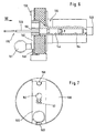
Im folgenden wird beschrieben, wie das Werkzeug in der Werkzeugaufnahme 30 dreh- und verschiebefest fixiert wird. Dazu wird zunächst auf die
Die Hülse 144 besteht aus gewöhnlichem Stahl, der vorzugsweise mit einer Korrosionsschutzbeschichtung versehen ist. Zusätzlich zur Verklebung kann eine nicht dargestellte Madenschraube verwendet werden, die die Hülse 144 mit dem Schaft 120 formschlüssig verbindet.The
Mit 146 ist eine Anfasung bezeichnet, über die der fluiddichte Anschluss zur Strömungsmittelquelle erfolgt.
Die Besonderheit der Ausführungsform nach
Zu diesem Zweck kommt eine in der Stirnfläche der Aufnahme 130 radial gegen eine Feder 148 verschiebbare Riegelplatte 150 zur Anwendung, in der eine Schlüssellochöffnung 152 ausgebildet ist. Wenn die Riegelplatte 150 mit Betätigungsknopf 151 gegen die Kraft der Feder 148 in
Wenn demnach - wie mit den Pfeilen in
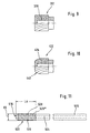
In den
Auch hier trägt der Schaft 220 auf der dem in der Formgebung etwas variierten Schneidkopf 222 abgewandten Seite einen Befestigungs- und Fixierungskörper 244, mit dem das Werkzeug in einer Werkzeugaufnahme dreh- und verschiebefest fixierbar ist. Dieser Körper hat im wesentlichen Rechteckform und wirkt mit einer nicht näher dargestellten hinterschnittenen Ausnehmung in der Werkzeugaufnahme zusammen, die nach der Art eines Bajonettverschlusses aufgebaut ist.Again, the
Vorstehend wurde bereits erwähnt, dass der Strömungsmitteldruck in verhältnismäßig hohe Bereiche angehoben werden sollte, um die ausreichende radiale Auslenkung des Werkzeugschafts sicherzustellen. Die Druckerzeugungsvorrichtung sollte in der Lage sein, einen Strömungsmitteldruck in einem Bereich von 30 bis 3000 bar zu erzeugen. Für bestimmte Gestaltungen des Werkzeugschafts und/oder der Spielpassung zwischen Werkzeug und Aufnahme können aber schon Drücke von 3 bar ausreichend sein.It has already been mentioned above that the fluid pressure should be raised to relatively high levels to ensure sufficient radial deflection of the tool shank. The pressure generating device should be capable of producing a fluid pressure in a range of 30 to 3000 bar. For certain designs of the tool shank and / or the clearance fit between the tool and the receptacle, however, pressures of 3 bar may be sufficient.
Vorzugsweise wird die Relativ-Drehzahl wischen Werkzeug und Werkstück im Bereich zwischen 100 und 50000 U/min gehalten, wobei die Schnittgeschwindigkeit im Bereich zwischen 20 und 300 m/min gewählt wird.Preferably, the relative speed between tool and workpiece is in the range between 100 and 50,000 Rpm, the cutting speed being selected in the range between 20 and 300 m / min.
In den
Der Schneidkopf 222 der Variante nach
Zumindest der Schneidkopf des Werkzeugs bzw. Entgratwerkzeugs ist vorzugsweise aus einem hochfesten Werkstoff gefertigt, wie z.B. aus Hartmetall, Schnellstahl wie HSS, HSSE oder, HSSEBM, Keramik, Cermet oder aus einem anderen Sintermetall-Werkstoff. Es kann zumindest im Bereich der am höchsten beanspruchten Abschnitte, d.h. im Bereich der zumindest einen Schneidkante 20* mit einer Beschichtung versehen sein, die vorzugsweise als Hartstoffschicht ausgebildet ist.At least the cutting head of the tool or deburring tool is preferably made of a high strength material, e.g. made of tungsten carbide, high-speed steel such as HSS, HSSE or, HSSEBM, ceramic, cermet or another sintered metal material. At least in the region of the most stressed sections, i. be provided in the region of at least one
Für diese Hartstoffschicht kommt z.B. Diamant, vorzugsweise nanokristalliner Diamant in Frage, Titan-Nitrid- oder Titan-Aluminium-Nitrid. Besonders geeignet sind u.a. eine Titan-Aluminium-Nitrid-Schicht und eine sogenannte Mehrlagen-Schicht, die unter der Bezeichnung "Fire I" von der Firma Gühring oHG vermarktet wird. Dabei handelt es sich um eine TiN-/(Ti,Al)N-Mehrlagen-Schicht.For this hard material layer is e.g. Diamond, preferably nanocrystalline diamond in question, titanium-nitride or titanium-aluminum-nitride. Particularly suitable are u.a. a titanium-aluminum-nitride layer and a so-called multilayer coating, which is marketed under the name "Fire I" by Guhring oHG. This is a TiN / (Ti, Al) N multilayer coating.
Besonders bevorzugt kann auch eine Verschleißschutzschicht zur Anwendung kommen, die im wesentlichen aus Nitriden mit den Metallkomponenten Cr, Ti und Al und vorzugsweise einem geringen Anteil von Elementen zur Kornverfeinerung besteht, wobei der Cr-Anteil bei 30 bis 65 %, vorzugsweise 30 bis 60 %, besonders bevorzugt 40 bis 60 %, der Al-Anteil bei 15 bis 35 %, vorzugsweise 17 bis 25 %, und der Ti-Anteil bei 16 bis 40 %, vorzugsweise 16 bis 35 %, besonders bevorzugt 24 bis 35 %, liegt, und zwar jeweils bezogen auf alle Metallatome in der gesamten Schicht. Dabei kann der Schichtaufbau eilagig sein mit einer homogenen Mischphase oder er kann aus mehreren in sich homogenen Lagen bestehen, die abwechselnd einerseits aus (TixAlyYz)N mit x = 0,38 bis 0,5 und y = 0,48 bis 0,6 und z = 0 bis 0,04 und andererseits aus CrN bestehen, wobei vorzugsweise die oberste Lage der Verschleißschutzschicht von der CrN-Schicht gebildet ist.Particularly preferably, a wear protection layer may be used, which consists essentially of nitrides with the metal components Cr, Ti and Al and preferably a small proportion of elements for grain refinement, wherein the Cr content at 30 to 65%, preferably 30 to 60%, particularly preferably 40 to 60%, the Al content at 15 to 35%, preferably 17 to 25%, and the Ti content is 16 to 40%, preferably 16 to 35%, particularly preferably 24 to 35%, in each case based on all metal atoms in the entire layer. In this case, the layer structure can be eilagig with a homogeneous mixing phase or it can consist of several self-homogeneous layers, alternately on the one hand of (Ti x Al y Y z ) N with x = 0.38 to 0.5 and y = 0.48 to 0.6 and z = 0 to 0.04 and on the other hand consist of CrN, wherein preferably the uppermost layer of the wear protection layer is formed by the CrN layer.
Weitere Ausführungsformen sind in den
Gemäß
Ein zentrischer Strömungsmittelkanal 524 erstreckt sich durch den gesamten Werkzeugkörper und ist strinseitig bei 570 verschlossen. Der Schneidkopf 522 mit einer axialen Länge LA von beispielsweise 5 mm ist als Reibwerkzeug gestaltet und hat eine Viekzahl - nämlich 14 - von wendelförmig verlaufenden Schneidkanten 520*. Im Abstand von beispielsweise 3 mm von der Schneidkopfspitze sind zwei Mündungsöffungen 528 von Stichkanälen 526 vorhanden, die so verlaufen, dass ihre Achsen 527 in einer gemeinsamen Radialebene ER liegen (vgl.
Selbstverständlich ist es nicht erforderlich, dass die Achsen 527 der Stichkanäle 526 auf der Mittelschse des Strömungsmittelkanals senkrecht stehen. Es ist beispielsweise bei dem Werkzeug nach
Man erkennt aus der Dartellung nach
Das Werkzeug nach
In den
Der Schneidkopf 622 hat 16 wendelformig verlaufende Schneidkanten 620*, zwischen denen ebenso viele Spannuten 631 verbleiben. Der Schneidkanten-Fußdurchmesser FDS liegt beispielsweise bei etwa 12 mm.The cutting
Wie sich aus
Vom Strömungsmittelkanal 624 gehen - wie in
Wie sich aus
Die Wirkungsweise der Werkzeuge nach den
Vorstehend wurden Ausführungsformen beschrieben, bei denen der hydrostatische Staudruck eines im Inneren des Werkzeugs zugeführten Strömungsmittels dazu genutzt wird, eine in das Werkzeug integrierte Radialkraft-Erzeugungseinrichtung bereit zu stellen, mit der der Schneidkopf, dessen Durchmesser so gewählt ist, dass er mit radialem Spiel entweder in die Ausnehmung oder in die Bohrung einführbar ist, bei seiner Drehbewegung vorzugsweise gesteuert radial auslenkbar ist. Diese Variante setzt voraus, dass der Austritt des Strömungsmittels im Bereich einer Innenwand und zwar derart erfolgt, dass die Innenwand der Mündung gegenüberliegt. Mit anderen Worten, der Schneidkopf der Ausführungsformen nach den
Um die gesamte axiale Länge des Schneidkopfs und sogar den Bereich eines Übergangs zum Schaft für einen Entgratvorgang nutzen zu können, dient die Weiterbildung der
Mit dieser Weiterbildung soll insbesondere das Entgraten der Stellen 717 der Bohrung 714 vereinfacht werden, indem ein rückwärtiger Anschnitt bzw. Rundungsübergang 741 des Schneidkopfs 722 genutzt wird. Der Schneidkopf 722 selbst kann hinsichtlich Geometrie, Material und Eigenschaften in gleicher Weise wie vorstehend beschrieben bzw. in den Ansprüchen umrissen ausgebildet werden, so dass darauf hier nicht näher eingegangen wird. Wie schematisch angedeutet, können die zum Entgraten vorgesehenen Schneidkanten durch eine sogenannte BIAX-Riffelung 750 gebildet sein. Es sind aber auch andere Geometrien der Schneidkanten gleichermaßen möglich.With this development, in particular the deburring of the
Damit eine hydrostatische Auslenkkraft auch dann erzeugbar ist, wenn der Schneidkopf 722 die Bohrung 714 weitgehend verlassen hat, trägt der Schaft 720 im Axialabstand zum Schneidkopf einen Führungs- und Stützkörper 752, der einen Durchmesser DF hat, welcher derart an den Innendurchmesser der Bohrung 714 angepasst ist, dass ein Funktionsspalt 754 vorbestimmter Weite ausgebildet wird. Dieser Funktionsspalt kann über den Umfang variieren; entscheidend ist das Maß im Bereich der Mündungsöffnungen 728*. Man erkennt aus der Darstellung der
Die vortehend beschriebenen Varianten integrieren die Radialkraft-Erzeugungseinrichtung in Form eines innenliegenden Druckfluid-Kanalsystems in das Werkzeug. Eine Alternative ist in
Hier wird die gesteuerte radiale Auslenkung des Schneidkopfs durch eine dynamische Kraft, nämlich durch die Fliehkraft einer Unwuchtmasse erzeugt. Der Schneidkopf 822 kann wiederum so ausgebildet sein, wie er in einer der zuvor beschriebenen Varianten erläutert wurde, beispielsweise also wie in
Anstelle eines gesonderten Unwuchtkörpers können selbstverständlich auch andere Maßnahmen zur Erzeugung der Unwuchtkräfte ergriffen werden. Die Unwucht kann beispielsweise in das Werkzeug einstückig integriert sein, indem ein asymmetrischer Anschliff angebracht ist.Of course, other measures for generating the imbalance forces can be taken instead of a separate imbalance body. The unbalance can for example be integrally integrated into the tool by an asymmetrical bevel is attached.
Anhand der
Mit strichpunktierter Linie ist der Spitzenbereich des Entgratungswerkzeugs 910 angedeutet, dessen Schneidkopf 922 soweit in die Bohrung 914 eingeführt ist, dass die Austrittskante 972 entgratet werden kann.A dotted line indicates the tip region of the
Das Werkzeug 910 ist in
An einen Einspannabschnitt 944 schließt sich ein Schaft 920 an, dessen Länge LS mindestens dem Maß TT der Bohrung 970 entspricht und dessen Durchmesser DS so gewählt ist, dass der Schaft 920 mit vorbestimmtem Radialspiel SR in der Bohrung 970 aufgenommen werden kann. Die Lagezuordnung zwischen der Bohrung 970 und dem für den Entgratvorgang in die Bohrung eingeführten Werkzeug 910 ist in
Der Schaft 920 hat wiederum eine Innenbohrung 924, über die Druckmittel von Einspannabschnitt 944 zuführbar ist. Mit dem Bezugszeichen 926 ist ein Radialkanal bezeichnet, dessen Mündungsöffnung der Innenwandung der Bohrung 970 in vorbestimmtem Abstand gegenüber liegt.The
Der Schaft 920 trägt auf der dem Körper 944 abgewandten Seite eine sogenannte Entgratungslanze 974, die am Ende eines Stifts 976 den eigentlichen Schneidkopf 922 trägt. Der Durchmesser D922 des Schneidkopfs ist geringfügig kleiner als der Durchmesser D914 der Bohrung 914. Wie ferner aus der
Aus der Beschreibung des Werkzeugs ist ersichtlich, dass bei Druckbeaufschlagung der Innenbohrung 924 durch die über den Umfang ungleichmäßige Verteilung der Radialbohrungen 926 eine radiale Auslenkung des Schafts 920 und damit des Schneidkopfs 922 hervorgerufen werden kann, wodurch der Entgratungsvorgang durchgeführt werden kann. Ebenso wie an der Stelle 972 kann auch der Bereich 978 der Bohrung 914 entgratet werden.From the description of the tool, it can be seen that when the
Die Ausgestaltung des Werkzeugs nach
Selbstverständlich ist die Form des Schneidkopfs 922 nicht auf die dargestellte Geometrie beschränkt. Es können vielmehr alle gängigen Geometrien zur Anwendung kommen, wobei auch die Ausgestaltung der Schneiden in weiten Grenzen variiert werden kann. Je nach axialer Länge der Bohrung 914 wird die Länge L976 des Stifts 976 ausgewählt.Of course, the shape of the cutting
Bezüglich der Gestaltung der Radialbohrung 926 besteht erneut ein großer Spielraum für die Gestaltung bzw. Variation nach Größe, Lage und Zahl, wie dies auch bei den zuvor beschriebenen Ausführungsbeispielen beschrieben worden ist.Regarding the design of the
Das Werkzeug gemäß
Selbstverständlich sind Abweichungen von den beschriebenen Ausführungsformen möglich, ohne den Grundgedanken der Erfindung zu verlassen.Of course, deviations from the described embodiments are possible without departing from the spirit of the invention.
So können beispielsweise mehrere innenliegende Strömungsmittelkanäle vorgesehen sein.For example, a plurality of internal fluid channels may be provided.
Wenn das Werkzeug zum Entgraten mehrerer in Axialrichtung gestaffelter Bohrungen herangezogen wird, ist es vorteilhaft, die Strömungsmittelversorgung des Werkzeug nur dann mit angehobenen Druck auszuführen, wenn der Schneidkopf in die Nähe der zu entgratenden Bohrungsmündung gelangt.When the tool is used for deburring a plurality of axially staggered holes, it is advantageous to perform the fluid supply of the tool only with increased pressure when the cutting head comes close to the bore to be deburred bore.
Auch bezüglich der Geometrie des Schneidkopfs soll die Erfindung nicht auf die dargestellten Ausführungsformen beschränkt sein. Beispiele für gängige und sinnvolle Gestaltungen des Schneidkopfs sind die Zylinderform, Flammenform, Kugelform, Walzenrundform, Spitzbogenform, Spitzkegelform, Rundbogenform, Scheibenform und Tropfenform, wie sie beispielsweise auch für Hartmetallfrässtifte - beispielsweise der Firma August Rüggeberg GmbH & Co. KG, PFERD-Werkzeuge, 51709 Marienheide - verwendet werden.Also with respect to the geometry of the cutting head, the invention should not be limited to the illustrated embodiments. Examples of common and useful designs of the cutting head are the cylindrical shape, flame shape, spherical shape, roll base, ogival shape, pointed cone shape, round arch shape, disc shape and teardrop shape, as for example for tungsten carbide burrs - for example, the company August Rüggeberg GmbH & Co. KG, PFERD tools, 51709 Marienheide - to be used.
Das unter relativ hohem Druck stehende Strömungsmittel kann zusätzlich auch zum Entgraten genutzt werden, sei es durch den "Wasserschneideffekt", d.h. durch den Aufbau eines Schneidstrahls allein oder durch die von der radial austrenden Strömungsmittelströmung hervorgerufene Staudruckkraft, die zu einer radialen Auslenkung des Werkzeugschafts und damit des Schneidkopfs führt.The under relatively high pressure fluid can also be used for deburring, be it by the "water cutting effect", ie by the construction of a cutting jet alone or by the dynamic pressure caused by the radially emerging fluid pressure dynamic pressure, which leads to a radial deflection of the tool shaft and thus the cutting head.
Die Erfindung schafft somit ein vorzugsweise drehangetriebenes Werkzeug zum Entgraten von Durchbrüchen wie zum Beispiel von Bohrungen, die seitlich in eine im wesentlichen zylindrische Ausnehmung münden. Das Werkzeug hat einen an einem Schaft sitzenden Schneidkopf, der zumindest eine Schneidkante hat, die sich zumindest abschnittsweise in axialer Richtung erstreckt. Damit das Entgraten zuverlässig und mit möglichst geringem Aufwand durchgeführt werden kann, ist in das Werkzeug eine Radialkraft-Erzeugungseinrichtung integriert, beispielsweise in Form zumindest eines innenliegenden Strömungsmittelkanals, von dem zumindest ein Stichkanal ausgeht, der im Bereich des Schneidkopfs vorzugsweise im Umfangsabstand zu der zumindest einen Schneidkante in dessen äußere Umfangsfläche mündet. Weil der Durchmesser des Schneidkopfs so gewählt ist, dass er mit radialem Spiel in die Ausnehmung einführbar ist, führt die entweder bei Drehung des Werkzeugs oder durch die Einspeisung von unter Druck stehendem Strömungsmittel erzeugte Radialkraft dazu, dass der Schneidkopf radial elastisch ausgelenkt wird, wodurch die Innenoberfläche der Ausnehmung sanft bearbeitet und dabei den Entgratvorgang zuverlässig durchführt werden kann.The invention thus provides a preferably rotationally driven tool for deburring apertures, such as bores, which open laterally into a substantially cylindrical recess. The tool has a cutting head which is seated on a shaft and has at least one cutting edge which extends at least in sections in the axial direction. Thus, the deburring can be performed reliably and with the least possible effort, a radial force generating device is integrated into the tool, for example in the form of at least one internal fluid channel from the at least one stitch channel emanating in the region of the cutting head preferably at a circumferential distance to the at least one Cutting edge opens into the outer peripheral surface. Because the diameter of the cutting head is selected to be radially insertable into the recess, the radial force generated either upon rotation of the tool or through the supply of pressurized fluid results in the cutting head being deflected radially elastically, thereby causing the cutting head to deflect The inner surface of the recess is gently machined while the deburring process can be performed reliably.
Claims (47)
- A tool for deburring a bore, such as for example bores that open laterally into a cylindrical recess (14) that is for example cylindrical, comprising a cutting head (22; 222; 522; 622) seated on a flexible shaft (20; 120; 220; 520; 620), the cutting head being adapted to be introduced into the recess or bore with radial play and having at least one cutting edge (20*; 520*; 620*) that extends, at least in sections, in the axial direction, characterized by a radial force-producing device (24, 26, 28; 244; 326; 426; 526, 528; 624, 626, 628; 724, 728*; 860, 826; 924, 926) that is integrated into the tool- either having the form of at least one internally situated flow medium channel (24; 124; 224; 524; 624; 924) from which at least one corresponding branch channel (26; 526; 626; 826) starts, which branch channel has at least one opening that opens into an external peripheral surface of the tool in the area of the cutting head or in axial vicinity of the latter, wherein a radial force relative to the recess or bore being generated by feeding pressurized flow medium such that the cutting head is deflected elastically and executes cutting processing as the result of a relative rotational movement between tool and workpiece,- or having the form of an imbalance mass (860), wherein said cutting head (822) is deflected elastically and executes cutting processing as the result of a relative rotational movement between tool and workpiece.
- A tool comprising a radial force-producing device which has a flow medium channel according to claim 1, characterized in that the tool is adapted to be driven rotationally, and the cutting head (22; 522; 622, 722; 822; 922), the diameter (DS) of which is selected such that it may be introduced into either the recess (14) or the bore (12) at radial play (SR), is adapted to be radially deflected during its rotational movement, preferably in a controlled manner, by making use of the flexibility of the shaft (20; 120; 220; 520; 620) supporting the cutting head (22; 522; 622, 722; 822; 922).
- The tool according to claim 2, characterized in that the branch channel (26; 526; 626) opens into the external peripheral surface of the tool at a peripheral distance from the at least one cutting edge (20*; 520*; 620*).
- The tool according to claim 2 or 3, characterized in that a plurality of branch channels (26; 526; 626) are provided with a corresponding number of openings (28; 528; 628) that are distributed over the peripheral surface in a non-uniform fashion such that the sum of the dynamic pressure forces produced in the area of the openings between the tool or the cutting head (22) and the inner wall of the recess (14) may deflect the shaft (20) in the radial direction.
- The tool according to any one of claims 2 to 4, characterized in that a plurality of branch channels (26; 626) are provided whose openings (28; 628) are staggered in the axial direction.
- The tool according to any one of claims 2 to 5, characterized in that the at least one branch channel (26; 526; 626) has a diameter in the range from 0.1 to 5 mm.
- The tool according to any one of claims 2 to 6, characterized in that a plurality of internally situated flow medium channels are provided.
- The tool according to any one of claims 2 to 6, characterized in that the at least one opening (26) is situated in the area of a cutting edge (20*).
- The tool according to any one of claims 2 to 6, characterized in that at least one of the openings (28; 528; 628) is situated in the area of a groove bottom between two adjacent cutting edges (20*).
- The tool according to any one of claims 2 to 9, characterized in that the at least one branch channel (26; 526; 626) has a rectilinear form or is formed by an eroded recess.
- The tool according to claim 10, characterized in that the angle (WN) formed by the branch channel (26) with the axis (38) of the tool (10) is in the range from 5 to 175 degrees, preferably between 40 and 60 degrees.
- The tool according to any one of claims 2 to 11, characterized in that on the side facing away from the cutting head, the shaft (20) carries an element (44; 144; 244A) via which the flow medium may be fed into the at least one flow medium channel (24; 124; 224).
- The tool according to claim 12, characterized in that the element for feeding in the flow medium at the same time forms a fastening and fixing element (44; 144) whereby the tool may be fixed in a tool holding fixture (30; 130) so as to be secured against rotation and sliding displacement.
- The tool according to any one of claims 2 to 13, characterized in that the plurality of the openings (526; 626) are situated in a peripheral area that is limited by a central angle (WZ) in a range from 120 to 140 degrees.
- The tool according to claim 14, characterized in that the plurality of openings (526; 626) are situated so as to be uniformly offset from one another in the peripheral direction.
- The tool according to any one of claims 2 to 15, characterized in that the openings (628) are situated on at least one line that is essentially helical.
- A tool comprising a radial force-producing device according to claim 1 which includes an imbalance mass, characterized in that the cutting head is adapted to be deflected radially in a controlled manner during its rotational movement.
- The tool according to claim 17, characterized in that the imbalance mass is formed in one piece with the tool.
- The tool according to claim 17, characterized in that the imbalance mass (860) is fastened to the tool as a separate component in a position-adjustable fashion.
- The tool according to any one of claims 1 to 19, characterized by a multiplicity of cutting edges (20*; 520*; 620*) distributed over the periphery.
- The tool according to any one of claims 1 to 20, characterized in that the shaft (20) has a length in a range from 5 to 1000 mm.
- The tool according any one of claims 1 to 21, characterized in that the shaft (20; 520; 620) is tapered in relation to the diameter (DS) of the cutting head (22; 522; 622).
- The tool according to any one of claims 1 to 22, characterized in that the at least one cutting edge (20*; 520*; 620*) is set at an angle with an axial plane (EA) of the tool (10).
- The tool according to any one of claims 1 to 23, characterized in that the cutting head (22; 722) has, at least on its side facing away from the shaft (20; 720), a notch (40; 740) that is preferably formed by a chamfer or a rounded section.
- The tool according to any one of claims 1 to 24, characterized in that the cutting head is adapted by at least a quantity situated between 0.1 and 5 mm.
- The tool according to any one of claims 1 to 25, characterized in that at least the cutting head is made of a high-strength material such as, e.g., wear-resistant steel, high-speed steel such as HSS, HSSE, or HSSEBM, hard metal, ceramic, cermet, or of another sintered metal material.
- The tool according to any one of claims 1 to 26, characterized in that the shaft (20) carries, on the side facing away from the cutting head (22), a fastening and fixing element (44; 144; 244) whereby the tool may be fixed in a tool holding fixture (30; 130) so as to be secured against rotation and sliding displacement..
- The tool according to any one of claims 1 to 27, characterized by being formed as a milling tool, a boring tool, in particular a deep hole boring tool, a straight-fluted boring or spiral boring tool, or as a reamer.
- The tool according to any one of claims 1 to 28, characterized in that the at least one cutting edge (620*) has a positive cutting angle (RSW).
- The tool according to any one of claims 1 to 28, characterized in that the at least one cutting edge (520*) has a negative cutting angle.
- The tool according to any one of claims 1 to 30, characterized in that the at least one cutting edge (520*) extends essentially in a helical form.
- The tool according to any one of claims 1 to 31, characterized in that at least the shaft (20; 920) is made of a high-strength material such as, e.g., a hard material, a hard metal, a cermet material or a compound material such as, e.g., a carbon-fiber plastic material, and has an elasticity such that the radial deflections of the cutting head and thus of the shaft that occur during the deburring process fall within the range of elastic deformation exclusively.
- The tool according to any one of claims 1 to 32, characterized by a coating preferably executed as a hard material coating such as, e.g., of diamond, preferably non-crystalline diamond, TiN, (Ti, Al)N, a multi-layer coating or a coating comprised of nitrides with the metal components Cr, Ti and Al, and preferably a low proportion of elements for grain refinement, wherein the Cr content is at 30 to 65%, the Al content is at 15 to 35%, and the Ti content is at 16 to 40%, preferably 16 to 35%, relative to all metal atoms in the overall coating.
- The tool according to claim 33, characterized in that the structure of the entire coating is made up of a homogenous mixed phase.
- The tool according to claim 33 or 34, characterized in that the structure of the entire coating is made up of a plurality of individual layers that are homogenous in themselves, alternatingly made up one the one hand of (TixAlyYz)N, with x = 0.38 to 0.5 and y = 0.48 to 0.6, and z = 0 to 0.04, and on the other hand of CrN, with the topmost layer of the wear protection coating preferentially being formed by the CrN layer.
- An apparatus for deburring bores that open laterally into an essentially cylindrical recess (14), by means of a tool comprising a radial force-producing device according to any one of claims 1 to 16 and 20 to 35 which includes a flow medium channel, characterized by a rotational drive device (32) and a flow medium source (36) for feeding pressurized flow medium into the at least one flow medium channel (24).
- The apparatus according to claim 36, characterized in that the flow medium is constituted by a liquid or gaseous cooling agent and lubricant.
- The apparatus according to claim 36 or 37, characterized in that a pressure producing device (36) is provided whereby a flow medium pressure in a range from 3 to 3000 bar may be produced.
- The apparatus according to any one of claims 36 to 38 including a tool according to claim 14, characterized by a tool holding fixture wherein the fastening and fixing element (244) is accommodated in the manner of a bayonet catch.
- An apparatus for deburring bores that open laterally into an essentially cylindrical recess (14), in particular according to any one of claims 37 to 40, including a tool comprising a radial force-producing device according to clam 1 and 13, that supports on the side facing away from the cutting head a prismatic, in particular cylindrical element for feeding in pressurized flow medium, characterized in that the fastening and fixing element (44;144) is adapted to be fixed in a manner preventing axial and rotational movement when subjected to flow medium pressure.
- The apparatus according to claim 40, characterized in that the tool holding fixture is equipped with a cylindrical receiving bore (154) for the element (144) for feeding in the flow medium, and with a radially adjustable locking element (150) formed with a keyhole opening (152), against which locking element a shoulder (156) of the fastening and fixing element (144) can be pressed when the flow medium pressure is fed into the fastening and fixing element (144).
- A method for deburring bores that open laterally into an essentially cylindrical recess (14), with the aid of an apparatus according to any one of claims 36 to 41, characterized in that the pressure of the flow medium that is passed through the tool (10) introduced into the recess (14) is used to radially deflect the cutting head (22) as a coherent part and thereby have the at least one cutting edge (20*) engage the chip to be removed.
- The method according to claim 42, characterized in that the flow medium pressure is raised to such a high level that the flow medium exiting from the at least one opening (28) forms a cutting jet whereby a machining processing can be effected.
- The method according to claim 42 or 43, characterized by the following method steps:a) introducing the tool (10), which is executing a relative rotational movement with respect to a workpiece provided with the recess (14), into the recess, andb) initiating a flow of the pressurized flow medium through the tool (10) at a concurrent radial deflection of the cutting head (22).
- The method according to claim 44, characterized in that during method step b), at least one of the tool (10) and the workpiece executes an advancing movement.
- The method according to any one of claims 42 to 45, characterized in that at least one of the tool (10) and the workpiece is driven with a rotational speed in the range between 100 and 50,000 RPM.
- The method according to any one of claims 42 to 46, characterized in that the cutting speed is selected in the range between 20 and 300 m/min.
Applications Claiming Priority (6)
| Application Number | Priority Date | Filing Date | Title |
|---|---|---|---|
| DE10222155 | 2002-05-17 | ||
| DE10222155 | 2002-05-17 | ||
| DE10248777 | 2002-10-18 | ||
| DE10248777 | 2002-10-18 | ||
| DE10321670 | 2003-05-14 | ||
| DE10321670A DE10321670A1 (en) | 2002-05-17 | 2003-05-14 | Tool, device and method for deburring bores |
Publications (2)
| Publication Number | Publication Date |
|---|---|
| EP1362659A1 EP1362659A1 (en) | 2003-11-19 |
| EP1362659B1 true EP1362659B1 (en) | 2011-03-23 |
Family
ID=29273277
Family Applications (1)
| Application Number | Title | Priority Date | Filing Date |
|---|---|---|---|
| EP03011272A Expired - Lifetime EP1362659B1 (en) | 2002-05-17 | 2003-05-16 | Tool, device and method for deburring bores |
Country Status (3)
| Country | Link |
|---|---|
| EP (1) | EP1362659B1 (en) |
| JP (1) | JP2004291224A (en) |
| PL (1) | PL360223A1 (en) |
Families Citing this family (11)
| Publication number | Priority date | Publication date | Assignee | Title |
|---|---|---|---|---|
| JP2003340631A (en) | 2002-05-17 | 2003-12-02 | Guehring Joerg | Tool, device and method for deburring bore hole |
| DE102004010372A1 (en) * | 2004-03-03 | 2005-09-22 | Gühring, Jörg, Dr. | Tool for deburring holes |
| AT502527B1 (en) * | 2005-09-12 | 2008-08-15 | Tement Franz | Cutting shaft tool for saving of time with regrinding and adjusting of tool machine, has shaft outer side formed of hard metal housing in which steel core is inserted |
| DE102006006564B4 (en) | 2006-01-23 | 2022-12-08 | Gühring KG | Tool for deburring bores and kit for such a tool |
| ITMI20071903A1 (en) | 2007-10-04 | 2009-04-05 | Getters Spa | METHOD FOR THE PRODUCTION OF SOLAR PANELS THROUGH THE USE OF A POLYMER TRISTRATE INCLUDING A COMPOSITE GETTER SYSTEM |
| JP2010149271A (en) * | 2008-11-26 | 2010-07-08 | Hitachi Ltd | Corner portion working tool |
| JP5469685B2 (en) * | 2012-01-06 | 2014-04-16 | 本田技研工業株式会社 | Deburring method and deburring mechanism |
| JP5862960B2 (en) * | 2012-12-17 | 2016-02-16 | 株式会社デンソー | Deburring method and burr removing device for workpiece |
| JP2015112690A (en) * | 2013-12-12 | 2015-06-22 | 自動車部品工業株式会社 | Deburring device for crossing hole and deburring method using the same |
| DE102016205657B4 (en) * | 2016-04-06 | 2021-06-10 | Gühring KG | CHIPPING TOOL FOR DEBURRING HOLES |
| CN106695020B (en) * | 2017-03-21 | 2018-10-30 | 唐山正元管业有限公司 | Small-diameter welded pipes Removing of inner burs device |
Citations (3)
| Publication number | Priority date | Publication date | Assignee | Title |
|---|---|---|---|---|
| DE1167302B (en) * | 1962-06-21 | 1964-04-09 | Kronprinz Ag | Method and device for supporting a steel holder when removing the inner ridge of longitudinally welded pipes |
| US20020013988A1 (en) * | 2000-06-28 | 2002-02-07 | Michael Kapgan | Burr removal apparatus |
| DE10118596A1 (en) * | 2001-04-12 | 2002-10-17 | Volkswagen Ag | Recess wall surface finishing device has lance with deformation at end for mechanical treatment of wall surface |
Family Cites Families (4)
| Publication number | Priority date | Publication date | Assignee | Title |
|---|---|---|---|---|
| US4563837A (en) * | 1982-06-14 | 1986-01-14 | Tokiwa Seiki Industrial Company, Limited | Ultra-precision grinding machine |
| DE3327409A1 (en) | 1983-07-29 | 1985-02-07 | Hawera Probst Gmbh + Co, 7980 Ravensburg | DRILLING TOOL FOR PRODUCING UNDERCUTS IN PRE-FABRED HOLES |
| US5238335A (en) * | 1987-06-11 | 1993-08-24 | Toshiba Tungaloy Co., Ltd. | Reamer |
| JPH08318419A (en) * | 1995-05-23 | 1996-12-03 | Kobe Steel Ltd | End mill |
-
2003
- 2003-05-16 EP EP03011272A patent/EP1362659B1/en not_active Expired - Lifetime
- 2003-05-19 JP JP2003140328A patent/JP2004291224A/en active Pending
- 2003-05-19 PL PL03360223A patent/PL360223A1/en not_active IP Right Cessation
Patent Citations (3)
| Publication number | Priority date | Publication date | Assignee | Title |
|---|---|---|---|---|
| DE1167302B (en) * | 1962-06-21 | 1964-04-09 | Kronprinz Ag | Method and device for supporting a steel holder when removing the inner ridge of longitudinally welded pipes |
| US20020013988A1 (en) * | 2000-06-28 | 2002-02-07 | Michael Kapgan | Burr removal apparatus |
| DE10118596A1 (en) * | 2001-04-12 | 2002-10-17 | Volkswagen Ag | Recess wall surface finishing device has lance with deformation at end for mechanical treatment of wall surface |
Also Published As
| Publication number | Publication date |
|---|---|
| JP2004291224A (en) | 2004-10-21 |
| PL360223A1 (en) | 2003-12-01 |
| EP1362659A1 (en) | 2003-11-19 |
Similar Documents
| Publication | Publication Date | Title |
|---|---|---|
| EP1727639B1 (en) | Tool and method for trimming boreholes | |
| EP3085481B1 (en) | Drilling-chamfering combination tool | |
| EP2560778B1 (en) | Drill head for a deep hole drilling tool for bta deep hole drilling, and deep hole drilling tool | |
| EP2318166B1 (en) | Tool for machining a work piece | |
| DE3930936C2 (en) | Combined drilling and reaming tool | |
| EP2323792B1 (en) | Multiple edge drill | |
| WO1984001117A1 (en) | Boring and milling head and boring and milling tool fixed inside the head; process for boring and milling a work piece | |
| CH678834A5 (en) | ||
| DE3124532A1 (en) | DRILLING TOOL | |
| EP2635394B1 (en) | Gun drill | |
| EP1362659B1 (en) | Tool, device and method for deburring bores | |
| WO2005089973A1 (en) | Flow moulding drilling method with simultaneous thread and flow moulding drilling tool for carrying out said method | |
| DE102010002669A1 (en) | Rotary drivable cutting tool | |
| DE10321670A1 (en) | Tool, device and method for deburring bores | |
| EP0684099B1 (en) | Combination tool | |
| DE3727103C2 (en) | ||
| DE102017112696A1 (en) | cutting tool | |
| DE10112165B4 (en) | Rod cutter head for gear cutting | |
| DE19735024B4 (en) | Drill for additional backside machining | |
| EP3439816B1 (en) | Reamer | |
| DE102006006564B4 (en) | Tool for deburring bores and kit for such a tool | |
| EP0123787B1 (en) | Tool for boring deep holes | |
| DE102006028393A1 (en) | Nozzle for treating e.g. mechanically machined interior of workpiece has nozzle channel whereby nozzle is designed such that nozzle channel, starting from bottom end area of supply borehole, extends at an angle to supply bore hole | |
| EP3036058B1 (en) | Device and method for the deburring of tubes | |
| EP3658320B1 (en) | Cutting tool comprising an adjusting device |
Legal Events
| Date | Code | Title | Description |
|---|---|---|---|
| PUAI | Public reference made under article 153(3) epc to a published international application that has entered the european phase |
Free format text: ORIGINAL CODE: 0009012 |
|
| AK | Designated contracting states |
Kind code of ref document: A1 Designated state(s): AT BE BG CH CY CZ DE DK EE ES FI FR GB GR HU IE IT LI LU MC NL PT RO SE SI SK TR |
|
| AX | Request for extension of the european patent |
Extension state: AL LT LV MK |
|
| 17P | Request for examination filed |
Effective date: 20040419 |
|
| AKX | Designation fees paid |
Designated state(s): AT BE BG CH CY CZ DE DK EE ES FI FR GB GR HU IE IT LI LU MC NL PT RO SE SI SK TR |
|
| 17Q | First examination report despatched |
Effective date: 20040701 |
|
| 17Q | First examination report despatched |
Effective date: 20040701 |
|
| GRAP | Despatch of communication of intention to grant a patent |
Free format text: ORIGINAL CODE: EPIDOSNIGR1 |
|
| GRAS | Grant fee paid |
Free format text: ORIGINAL CODE: EPIDOSNIGR3 |
|
| GRAA | (expected) grant |
Free format text: ORIGINAL CODE: 0009210 |
|
| AK | Designated contracting states |
Kind code of ref document: B1 Designated state(s): AT BE BG CH CY CZ DE DK EE ES FI FR GB GR HU IE IT LI LU MC NL PT RO SE SI SK TR |
|
| REG | Reference to a national code |
Ref country code: GB Ref legal event code: FG4D Free format text: NOT ENGLISH |
|
| REG | Reference to a national code |
Ref country code: CH Ref legal event code: EP |
|
| REG | Reference to a national code |
Ref country code: IE Ref legal event code: FG4D |
|
| REF | Corresponds to: |
Ref document number: 50313558 Country of ref document: DE Date of ref document: 20110505 Kind code of ref document: P |
|
| REG | Reference to a national code |
Ref country code: DE Ref legal event code: R096 Ref document number: 50313558 Country of ref document: DE Effective date: 20110505 |
|
| REG | Reference to a national code |
Ref country code: NL Ref legal event code: VDEP Effective date: 20110323 |
|
| PG25 | Lapsed in a contracting state [announced via postgrant information from national office to epo] |
Ref country code: GR Free format text: LAPSE BECAUSE OF FAILURE TO SUBMIT A TRANSLATION OF THE DESCRIPTION OR TO PAY THE FEE WITHIN THE PRESCRIBED TIME-LIMIT Effective date: 20110624 Ref country code: SE Free format text: LAPSE BECAUSE OF FAILURE TO SUBMIT A TRANSLATION OF THE DESCRIPTION OR TO PAY THE FEE WITHIN THE PRESCRIBED TIME-LIMIT Effective date: 20110323 |
|
| PG25 | Lapsed in a contracting state [announced via postgrant information from national office to epo] |
Ref country code: CY Free format text: LAPSE BECAUSE OF FAILURE TO SUBMIT A TRANSLATION OF THE DESCRIPTION OR TO PAY THE FEE WITHIN THE PRESCRIBED TIME-LIMIT Effective date: 20110323 Ref country code: FI Free format text: LAPSE BECAUSE OF FAILURE TO SUBMIT A TRANSLATION OF THE DESCRIPTION OR TO PAY THE FEE WITHIN THE PRESCRIBED TIME-LIMIT Effective date: 20110323 Ref country code: BG Free format text: LAPSE BECAUSE OF FAILURE TO SUBMIT A TRANSLATION OF THE DESCRIPTION OR TO PAY THE FEE WITHIN THE PRESCRIBED TIME-LIMIT Effective date: 20110623 Ref country code: SI Free format text: LAPSE BECAUSE OF FAILURE TO SUBMIT A TRANSLATION OF THE DESCRIPTION OR TO PAY THE FEE WITHIN THE PRESCRIBED TIME-LIMIT Effective date: 20110323 |
|
| REG | Reference to a national code |
Ref country code: IE Ref legal event code: FD4D |
|
| PG25 | Lapsed in a contracting state [announced via postgrant information from national office to epo] |
Ref country code: PT Free format text: LAPSE BECAUSE OF FAILURE TO SUBMIT A TRANSLATION OF THE DESCRIPTION OR TO PAY THE FEE WITHIN THE PRESCRIBED TIME-LIMIT Effective date: 20110725 Ref country code: EE Free format text: LAPSE BECAUSE OF FAILURE TO SUBMIT A TRANSLATION OF THE DESCRIPTION OR TO PAY THE FEE WITHIN THE PRESCRIBED TIME-LIMIT Effective date: 20110323 |
|
| BERE | Be: lapsed |
Owner name: GUHRING, JORG, DR. Effective date: 20110531 |
|
| PG25 | Lapsed in a contracting state [announced via postgrant information from national office to epo] |
Ref country code: SK Free format text: LAPSE BECAUSE OF FAILURE TO SUBMIT A TRANSLATION OF THE DESCRIPTION OR TO PAY THE FEE WITHIN THE PRESCRIBED TIME-LIMIT Effective date: 20110323 Ref country code: RO Free format text: LAPSE BECAUSE OF FAILURE TO SUBMIT A TRANSLATION OF THE DESCRIPTION OR TO PAY THE FEE WITHIN THE PRESCRIBED TIME-LIMIT Effective date: 20110323 Ref country code: CZ Free format text: LAPSE BECAUSE OF FAILURE TO SUBMIT A TRANSLATION OF THE DESCRIPTION OR TO PAY THE FEE WITHIN THE PRESCRIBED TIME-LIMIT Effective date: 20110323 Ref country code: ES Free format text: LAPSE BECAUSE OF FAILURE TO SUBMIT A TRANSLATION OF THE DESCRIPTION OR TO PAY THE FEE WITHIN THE PRESCRIBED TIME-LIMIT Effective date: 20110704 |
|
| PG25 | Lapsed in a contracting state [announced via postgrant information from national office to epo] |
Ref country code: MC Free format text: LAPSE BECAUSE OF NON-PAYMENT OF DUE FEES Effective date: 20110531 Ref country code: NL Free format text: LAPSE BECAUSE OF FAILURE TO SUBMIT A TRANSLATION OF THE DESCRIPTION OR TO PAY THE FEE WITHIN THE PRESCRIBED TIME-LIMIT Effective date: 20110323 |
|
| REG | Reference to a national code |
Ref country code: CH Ref legal event code: PL |
|
| PLBE | No opposition filed within time limit |
Free format text: ORIGINAL CODE: 0009261 |
|
| STAA | Information on the status of an ep patent application or granted ep patent |
Free format text: STATUS: NO OPPOSITION FILED WITHIN TIME LIMIT |
|
| PG25 | Lapsed in a contracting state [announced via postgrant information from national office to epo] |
Ref country code: LI Free format text: LAPSE BECAUSE OF NON-PAYMENT OF DUE FEES Effective date: 20110531 Ref country code: CH Free format text: LAPSE BECAUSE OF NON-PAYMENT OF DUE FEES Effective date: 20110531 Ref country code: IE Free format text: LAPSE BECAUSE OF FAILURE TO SUBMIT A TRANSLATION OF THE DESCRIPTION OR TO PAY THE FEE WITHIN THE PRESCRIBED TIME-LIMIT Effective date: 20110323 |
|
| REG | Reference to a national code |
Ref country code: FR Ref legal event code: ST Effective date: 20120131 |
|
| 26N | No opposition filed |
Effective date: 20111227 |
|
| GBPC | Gb: european patent ceased through non-payment of renewal fee |
Effective date: 20110623 |
|
| PG25 | Lapsed in a contracting state [announced via postgrant information from national office to epo] |
Ref country code: DK Free format text: LAPSE BECAUSE OF FAILURE TO SUBMIT A TRANSLATION OF THE DESCRIPTION OR TO PAY THE FEE WITHIN THE PRESCRIBED TIME-LIMIT Effective date: 20110323 |
|
| PG25 | Lapsed in a contracting state [announced via postgrant information from national office to epo] |
Ref country code: BE Free format text: LAPSE BECAUSE OF NON-PAYMENT OF DUE FEES Effective date: 20110531 |
|
| REG | Reference to a national code |
Ref country code: DE Ref legal event code: R097 Ref document number: 50313558 Country of ref document: DE Effective date: 20111227 |
|
| PG25 | Lapsed in a contracting state [announced via postgrant information from national office to epo] |
Ref country code: FR Free format text: LAPSE BECAUSE OF NON-PAYMENT OF DUE FEES Effective date: 20110531 |
|
| PG25 | Lapsed in a contracting state [announced via postgrant information from national office to epo] |
Ref country code: IT Free format text: LAPSE BECAUSE OF FAILURE TO SUBMIT A TRANSLATION OF THE DESCRIPTION OR TO PAY THE FEE WITHIN THE PRESCRIBED TIME-LIMIT Effective date: 20110323 |
|
| PG25 | Lapsed in a contracting state [announced via postgrant information from national office to epo] |
Ref country code: GB Free format text: LAPSE BECAUSE OF NON-PAYMENT OF DUE FEES Effective date: 20110623 |
|
| REG | Reference to a national code |
Ref country code: AT Ref legal event code: MM01 Ref document number: 502713 Country of ref document: AT Kind code of ref document: T Effective date: 20110516 |
|
| PG25 | Lapsed in a contracting state [announced via postgrant information from national office to epo] |
Ref country code: AT Free format text: LAPSE BECAUSE OF NON-PAYMENT OF DUE FEES Effective date: 20110516 |
|
| PG25 | Lapsed in a contracting state [announced via postgrant information from national office to epo] |
Ref country code: LU Free format text: LAPSE BECAUSE OF NON-PAYMENT OF DUE FEES Effective date: 20110516 |
|
| PG25 | Lapsed in a contracting state [announced via postgrant information from national office to epo] |
Ref country code: TR Free format text: LAPSE BECAUSE OF FAILURE TO SUBMIT A TRANSLATION OF THE DESCRIPTION OR TO PAY THE FEE WITHIN THE PRESCRIBED TIME-LIMIT Effective date: 20110323 |
|
| PG25 | Lapsed in a contracting state [announced via postgrant information from national office to epo] |
Ref country code: HU Free format text: LAPSE BECAUSE OF FAILURE TO SUBMIT A TRANSLATION OF THE DESCRIPTION OR TO PAY THE FEE WITHIN THE PRESCRIBED TIME-LIMIT Effective date: 20110323 |
|
| PGFP | Annual fee paid to national office [announced via postgrant information from national office to epo] |
Ref country code: DE Payment date: 20221116 Year of fee payment: 20 |
|
| REG | Reference to a national code |
Ref country code: DE Ref legal event code: R071 Ref document number: 50313558 Country of ref document: DE |