EP1362204B1 - Leitungsanordnung - Google Patents
Leitungsanordnung Download PDFInfo
- Publication number
- EP1362204B1 EP1362204B1 EP02714119A EP02714119A EP1362204B1 EP 1362204 B1 EP1362204 B1 EP 1362204B1 EP 02714119 A EP02714119 A EP 02714119A EP 02714119 A EP02714119 A EP 02714119A EP 1362204 B1 EP1362204 B1 EP 1362204B1
- Authority
- EP
- European Patent Office
- Prior art keywords
- hose
- pump
- line
- pipe
- liquid media
- Prior art date
- Legal status (The legal status is an assumption and is not a legal conclusion. Google has not performed a legal analysis and makes no representation as to the accuracy of the status listed.)
- Expired - Lifetime
Links
Images
Classifications
-
- F—MECHANICAL ENGINEERING; LIGHTING; HEATING; WEAPONS; BLASTING
- F16—ENGINEERING ELEMENTS AND UNITS; GENERAL MEASURES FOR PRODUCING AND MAINTAINING EFFECTIVE FUNCTIONING OF MACHINES OR INSTALLATIONS; THERMAL INSULATION IN GENERAL
- F16L—PIPES; JOINTS OR FITTINGS FOR PIPES; SUPPORTS FOR PIPES, CABLES OR PROTECTIVE TUBING; MEANS FOR THERMAL INSULATION IN GENERAL
- F16L55/00—Devices or appurtenances for use in, or in connection with, pipes or pipe systems
- F16L55/04—Devices damping pulsations or vibrations in fluids
- F16L55/045—Devices damping pulsations or vibrations in fluids specially adapted to prevent or minimise the effects of water hammer
-
- F—MECHANICAL ENGINEERING; LIGHTING; HEATING; WEAPONS; BLASTING
- F16—ENGINEERING ELEMENTS AND UNITS; GENERAL MEASURES FOR PRODUCING AND MAINTAINING EFFECTIVE FUNCTIONING OF MACHINES OR INSTALLATIONS; THERMAL INSULATION IN GENERAL
- F16L—PIPES; JOINTS OR FITTINGS FOR PIPES; SUPPORTS FOR PIPES, CABLES OR PROTECTIVE TUBING; MEANS FOR THERMAL INSULATION IN GENERAL
- F16L55/00—Devices or appurtenances for use in, or in connection with, pipes or pipe systems
- F16L55/04—Devices damping pulsations or vibrations in fluids
- F16L55/043—Devices damping pulsations or vibrations in fluids specially adapted for protecting instruments from water hammer or vibrations
Definitions
- the invention relates to a line arrangement for transmission of volume flows of liquid media associated with a pump Connection, a connection assigned to a consumer and one connecting the pump with the consumer Link.
- JP-A-11 294679 shows another one in FIG Conduit arrangement for reducing pressure pulsations gaseous medium.
- the known damping element acts as follows: pressure pulsations run in the hose assembly described above the Inner tube part first in the empty chamber. A part of migratory pulsation waves will be in the void chamber in propagate downstream, while another part in the upstream direction in the elongated annular Propagate space between inner and outer tube part becomes.
- the upstream waves are at the inner Front wall of the connecting piece deflected to the annular Cavity again to migrate downstream and with the from inner tube part exiting migrating pulsation waves to overlay. This overlay process is superimposed the waves partly out of phase, creating a dampening economy is achieved.
- the present invention is the Task is based, a line arrangement for the transmission of To provide flow rates of the type mentioned, in the the damping effect is enhanced.
- the solution according to the invention is characterized that in the line arrangement at least one non-perfused Line is provided by a connecting line branches off between pump and consumer. These are not flowed through line consists at least partially of a elastic hose and is facing away from the diversion at her Closed end.
- the non-flowed line can due to the compliance of the hose wall at elevated pressures replace a larger volume and thereby compensate for pressure pulsations. If such a non-perfused, yielding Hose connected to a described hose assembly, so does the described damping effect way the entire line arrangement. It is by the inventive Arrangement a significant attenuation of the pulsations achieved, which in particular by drastically lower noise emissions the pump shows.
- the elastic hose can extend over the entire length of the extend not flowed line. He can, too extend only over part of this line, with the other Part consists for example of a metal tube.
- the non-perfused branches Line directly to the pump assigned Connection of the connecting line from. In this case This results in particularly good damping levels.
- the branch but also in any other area of the interconnector respectively.
- an inner hose smaller diameter provided in the outer Hose is aligned coaxially. This one can with his one End attached to the outer elastic tube.
- the Connection of outer and inner tube, for example via a arranged between the outer and inner tube, with a end of the inner tube connected sleeve, with a sleeve-shaped clamp arranged around the outer tube is held.
- the connection can also be up Any other manner known to those skilled in the art done.
- the free, not connected to the sleeve end of the inner Hose is in the direction of the pump aligned.
- the sleeve can also be located in the middle of the inner tube, so that it has two free ends, one of which is in Towards the pump and another in the opposite direction has.
- the combination of additional nottechnikflossener Lead and one by additional inner Tubing achieved disruption of the fluid column in the conduit assembly can control the noise emissions over wide speed ranges
- the pump can be significantly reduced.
- inner tubes in the outer elastic Hose can be arranged. These can all be the same Direction or in different directions. Also the Length of inner tubes may vary. About the last mentioned variants, the degree of damping of the invention Line arrangement exactly to the particular application be set.
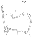
- a line arrangement 1 according to the invention for the Hydraulic system of an active chassis shown.
- the inventive can be applied to every other conceivable solution Hydraulic system find application in the case of transmission of Pressure and flow pulsations occur, such as in a power steering system.
- the line arrangement 1 connected to a pump, not shown.
- the line arrangement 1 with one is also not connected consumers connected.
- a connection line 4 is provided, which is the pump connects with the consumer.
- the connecting line 4 is made to a part of a metal tube 5 and another part from a flexible hose 6, which is made from a stand the technology known textile or metal reinforced hose is formed.
- connection line 7 At the terminal 2 branches off a further line 7.
- This line 7 has not flowed through. It is the line 7 to a stub, facing away from the branch 2 at her End 8 is closed.
- the stub line also exists made of an elastic, textile or metal reinforced hose. Depending on the application, the diversion to the stub can be done at each any other location of the flowed through connection line 4 between the pump and the consumer.
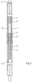
- stub 7 is shown in section. To the in the representation upwardly facing end 8 is the stub 8 closed. At the downward end leads the Line to port 2 with the pump.
- two inner tubes 9 and 11 are arranged in the stub 7. These two hoses have a smaller diameter as the outer tube of the stub 7 and are coaxial arranged in this.
- the hose 9 is over the hose end 8 final arrangement with the outer tube. 7 connected.
- the connection is made via a connected to the inner tube 11 in the outer tube 7 arranged sleeve 12.
- the outer diameter of the sleeve 12 is at least in some areas on the inner diameter of the outer Hose 7 tuned. So that the sleeve 12 in the outer Hose 7 does not slip, is outside the outer Hose 7, at the level of the sleeve 12 a sleeve-shaped clamp thirteenth intended.
- the two inner tubes 9 and 11 extend only over a portion of the outer stub 7. You point with their free ends towards the pump. You can also from the Point the pump away. This is not shown in the figures. They form with the stub 7 each an annular Room 14 and 15. Before the free ends of the inner Tubes 9 and 11 is formed in each case an empty chamber 16 and 17 respectively.
- the fluid column in the Death line 7 interrupted. This interruption causes that Pulsation waves are divided in the fluid column, then cover different paths, be partially reflected and meet again. Overlap at the meeting the pulsation waves are out of phase and are thereby damped.
- Hoses 9 and 11 in particular on the number, arrangement in the line 7, alignment in the line and length, can every complete system is precisely tuned and adjusted become.
- Hoses 9 and 11 corresponding hoses can also in the flexible hose 6 of the connecting line. 4 be provided.
Landscapes
- Engineering & Computer Science (AREA)
- General Engineering & Computer Science (AREA)
- Mechanical Engineering (AREA)
- Pipe Accessories (AREA)
Applications Claiming Priority (3)
| Application Number | Priority Date | Filing Date | Title |
|---|---|---|---|
| DE10107872 | 2001-02-20 | ||
| DE10107872A DE10107872C1 (de) | 2001-02-20 | 2001-02-20 | Leitungsanordnung zur Übertragung von Volumenströmen mit Dämpfungswirkung |
| PCT/EP2002/000824 WO2002066882A1 (de) | 2001-02-20 | 2002-01-26 | Leitungsanordnung |
Publications (2)
| Publication Number | Publication Date |
|---|---|
| EP1362204A1 EP1362204A1 (de) | 2003-11-19 |
| EP1362204B1 true EP1362204B1 (de) | 2005-01-19 |
Family
ID=7674680
Family Applications (1)
| Application Number | Title | Priority Date | Filing Date |
|---|---|---|---|
| EP02714119A Expired - Lifetime EP1362204B1 (de) | 2001-02-20 | 2002-01-26 | Leitungsanordnung |
Country Status (5)
| Country | Link |
|---|---|
| US (1) | US7051764B2 (enExample) |
| EP (1) | EP1362204B1 (enExample) |
| JP (1) | JP2004522079A (enExample) |
| DE (2) | DE10107872C1 (enExample) |
| WO (1) | WO2002066882A1 (enExample) |
Families Citing this family (4)
| Publication number | Priority date | Publication date | Assignee | Title |
|---|---|---|---|---|
| US20060225944A1 (en) * | 2005-04-11 | 2006-10-12 | Jack Abner | Multiple channel conduit hydraulic noise attenuation device |
| JP2007187099A (ja) * | 2006-01-13 | 2007-07-26 | Toyota Motor Corp | 燃料配管の防振構造 |
| DE102006039540B4 (de) * | 2006-08-23 | 2013-01-24 | Audi Ag | Druckpulsationsdämpfer für ein hydraulisches Hilfskraft-Lenksystem eines Kraftfahrzeugs |
| US8827034B2 (en) * | 2013-01-18 | 2014-09-09 | Halla Visteon Climate Control Corporation | Pressure pulsation dampening device |
Family Cites Families (21)
| Publication number | Priority date | Publication date | Assignee | Title |
|---|---|---|---|---|
| US3215164A (en) | 1962-07-05 | 1965-11-02 | Henry F Szczepanski | Water hammer dampener |
| US3323305A (en) * | 1964-10-16 | 1967-06-06 | Gen Motors Corp | Attenuating device |
| US4448217A (en) * | 1982-09-27 | 1984-05-15 | The Normand Trust | Accumulator having bladder in expansion limiting contact with casing |
| JPS5993590A (ja) | 1982-11-16 | 1984-05-30 | 日輪ゴム工業株式会社 | 高圧側ホ−ス |
| JPS60201194A (ja) | 1984-03-23 | 1985-10-11 | トヨタ自動車株式会社 | 流体圧用ホ−ス |
| JPH0317399U (enExample) | 1989-06-28 | 1991-02-20 | ||
| DE3922101A1 (de) * | 1989-07-05 | 1991-01-10 | Aeroquip Gmbh | Dehnschlauchleitung zur reduzierung der in hydraulikkreislaeufen durch hydropumpen hervorgerufenen druckpulsationen |
| DE9003635U1 (de) * | 1990-03-06 | 1990-07-05 | Ingenieurbüro H. Lüthin AG, Wettingen | Dehnschlauch zur Verringerung von Druckpulsationen |
| US5185002A (en) * | 1991-06-28 | 1993-02-09 | Alcon Surgical, Inc. | Transducer apparatus having water hammer dampening means |
| US5791141A (en) | 1994-04-29 | 1998-08-11 | Techco Corp. | Method and apparatus for reduction of fluid borne noise in hydraulic systems |
| US5582006A (en) * | 1994-04-29 | 1996-12-10 | Techco Corporation | Method and apparatus for reduction of fluid borne noise in hydraulic systems |
| IT1267644B1 (it) * | 1994-12-07 | 1997-02-07 | Dayco Europe Spa | Condotto per l'adduzione di un fluido con attenuazione delle pulsazioni di pressione |
| US5495711A (en) * | 1994-12-07 | 1996-03-05 | General Motors Corporation | Tuner hose assembly for power steering system |
| US5539164A (en) * | 1994-12-12 | 1996-07-23 | Dayco Products, Inc. | Power steering attenuation hose construction and method of making the same |
| JPH0979474A (ja) | 1995-09-11 | 1997-03-25 | Hitachi Constr Mach Co Ltd | 脈動低減配管ユニット |
| JPH10185075A (ja) | 1996-12-26 | 1998-07-14 | Hitachi Constr Mach Co Ltd | 脈動低減装置 |
| US6269841B1 (en) * | 1997-04-30 | 2001-08-07 | Dayco Products Llc | Energy attenuation apparatus for a system conveying liquid under pressure and method of attenuating energy in such a system |
| US6073656A (en) * | 1997-11-24 | 2000-06-13 | Dayco Products, Inc. | Energy attenuation device for a conduit conveying liquid under pressure, system incorporating same, and method of attenuating energy in a conduit |
| JPH11294679A (ja) | 1998-04-13 | 1999-10-29 | Mitsubishi Heavy Ind Ltd | 消音器および空気調和機 |
| US6688423B1 (en) * | 2000-11-03 | 2004-02-10 | Dana Corporation | Fluid-borne noise suppression |
| US6536457B2 (en) * | 2000-12-29 | 2003-03-25 | Pratt & Whitney Canada Corp. | Fluid and fuel delivery systems reducing pressure fluctuations and engines including such systems |
-
2001
- 2001-02-20 DE DE10107872A patent/DE10107872C1/de not_active Expired - Fee Related
-
2002
- 2002-01-26 JP JP2002566164A patent/JP2004522079A/ja active Pending
- 2002-01-26 WO PCT/EP2002/000824 patent/WO2002066882A1/de not_active Ceased
- 2002-01-26 DE DE50202045T patent/DE50202045D1/de not_active Expired - Fee Related
- 2002-01-26 US US10/468,460 patent/US7051764B2/en not_active Expired - Fee Related
- 2002-01-26 EP EP02714119A patent/EP1362204B1/de not_active Expired - Lifetime
Also Published As
| Publication number | Publication date |
|---|---|
| JP2004522079A (ja) | 2004-07-22 |
| DE50202045D1 (de) | 2005-02-24 |
| WO2002066882A1 (de) | 2002-08-29 |
| US7051764B2 (en) | 2006-05-30 |
| US20040112449A1 (en) | 2004-06-17 |
| EP1362204A1 (de) | 2003-11-19 |
| DE10107872C1 (de) | 2002-11-07 |
Similar Documents
| Publication | Publication Date | Title |
|---|---|---|
| DE3922101C2 (enExample) | ||
| DE3339876C2 (enExample) | ||
| DE69101803T2 (de) | Verbesserungen zu hydraulischen Antischwingungsbuchsen. | |
| EP0426789B1 (de) | Dehnschlauch zur verringerung von druckpulsationen | |
| DE69512934T2 (de) | Fluidzuleitung zur herabsetzung der druckschwingungen | |
| DE69525471T2 (de) | Hilfskraftlenkungsdämpfungskontraktion und herstellstellungsverfahren dafür | |
| DE102017117149B3 (de) | Hydraulische Lenkeinrichtung mit Lastsignal | |
| DE10056405B4 (de) | Kraftstoffhochdruckspeicher für ein Kraftstoffeinspritzsystem für Brennkraftmaschinen | |
| DE3510267C2 (de) | Zuleitungsschlauch zur Interferenz-Druckimpulsdämpfung | |
| EP0971164A2 (de) | Vorrichtung zum Reduzieren von Druckpulsationen in Hydraulikleitungen | |
| DE10015051A1 (de) | Vorrichtung zur Verringerung von Druckpulsationen | |
| DE102010043439A1 (de) | Kraftstoffeinspritzsystem einer Brennkraftmaschine | |
| DE102017113341A1 (de) | Aufbau für eine Schlauchleitung zur Förderung von Fluiden und Verfahren zum Bilden des Aufbaus mit einer Schlauchleitung zur Förderung von Fluiden | |
| EP1340016B1 (de) | Pulsationsdämpfer | |
| WO2008017544A1 (de) | Kraftstoffeinspritzsystem mit einem druckschwingungsdämpfer | |
| DE10215980B4 (de) | Leckageanschluss für einen Kraftstoffinjektor | |
| EP1362204B1 (de) | Leitungsanordnung | |
| DE3520881A1 (de) | Schlauch mit schwingungsabsorbierender eigenschaft | |
| EP2501973A1 (de) | Versorgungsschlauch für eine lackieranlage | |
| DE10351089A1 (de) | Verfahren zum Verringern von Druckpulsationen | |
| EP4571168A2 (de) | Anschlussstück für kraftstoffinjektor eines verbrennungsmotors | |
| DE102009049244A1 (de) | Dämpfungseinrichtung | |
| DE102006016938B3 (de) | Hydraulischer Pulsationsdämpfer und Verwendung eines hydraulischen Pulsationsdämpfers | |
| DE8226854U1 (de) | Schlauchfoermiges, verformbares verbindungselement | |
| EP1918626B1 (de) | Speicher zur Dämpfung von Druckpulsationen |
Legal Events
| Date | Code | Title | Description |
|---|---|---|---|
| PUAI | Public reference made under article 153(3) epc to a published international application that has entered the european phase |
Free format text: ORIGINAL CODE: 0009012 |
|
| 17P | Request for examination filed |
Effective date: 20030819 |
|
| AK | Designated contracting states |
Kind code of ref document: A1 Designated state(s): AT BE CH CY DE DK ES FI FR GB GR IE IT LI LU MC NL PT SE TR |
|
| RIN1 | Information on inventor provided before grant (corrected) |
Inventor name: SURGER, MARTIN Inventor name: SCHEYHING, FRANK Inventor name: KIESERLING, JOACHIM Inventor name: EHMANN, WERNER |
|
| GRAP | Despatch of communication of intention to grant a patent |
Free format text: ORIGINAL CODE: EPIDOSNIGR1 |
|
| GRAS | Grant fee paid |
Free format text: ORIGINAL CODE: EPIDOSNIGR3 |
|
| GRAA | (expected) grant |
Free format text: ORIGINAL CODE: 0009210 |
|
| AK | Designated contracting states |
Kind code of ref document: B1 Designated state(s): DE FR GB IT SE |
|
| REG | Reference to a national code |
Ref country code: GB Ref legal event code: FG4D Free format text: NOT ENGLISH |
|
| PGFP | Annual fee paid to national office [announced via postgrant information from national office to epo] |
Ref country code: DE Payment date: 20050208 Year of fee payment: 4 |
|
| PGFP | Annual fee paid to national office [announced via postgrant information from national office to epo] |
Ref country code: SE Payment date: 20050210 Year of fee payment: 4 Ref country code: FR Payment date: 20050210 Year of fee payment: 4 |
|
| REG | Reference to a national code |
Ref country code: IE Ref legal event code: FG4D Free format text: GERMAN |
|
| REF | Corresponds to: |
Ref document number: 50202045 Country of ref document: DE Date of ref document: 20050224 Kind code of ref document: P |
|
| REG | Reference to a national code |
Ref country code: SE Ref legal event code: TRGR |
|
| GBT | Gb: translation of ep patent filed (gb section 77(6)(a)/1977) |
Effective date: 20050225 |
|
| PLBE | No opposition filed within time limit |
Free format text: ORIGINAL CODE: 0009261 |
|
| STAA | Information on the status of an ep patent application or granted ep patent |
Free format text: STATUS: NO OPPOSITION FILED WITHIN TIME LIMIT |
|
| ET | Fr: translation filed | ||
| 26N | No opposition filed |
Effective date: 20051020 |
|
| PG25 | Lapsed in a contracting state [announced via postgrant information from national office to epo] |
Ref country code: GB Free format text: LAPSE BECAUSE OF NON-PAYMENT OF DUE FEES Effective date: 20060126 |
|
| PG25 | Lapsed in a contracting state [announced via postgrant information from national office to epo] |
Ref country code: SE Free format text: LAPSE BECAUSE OF NON-PAYMENT OF DUE FEES Effective date: 20060127 |
|
| PG25 | Lapsed in a contracting state [announced via postgrant information from national office to epo] |
Ref country code: FR Free format text: LAPSE BECAUSE OF NON-PAYMENT OF DUE FEES Effective date: 20060131 |
|
| PGFP | Annual fee paid to national office [announced via postgrant information from national office to epo] |
Ref country code: IT Payment date: 20060131 Year of fee payment: 5 |
|
| PG25 | Lapsed in a contracting state [announced via postgrant information from national office to epo] |
Ref country code: DE Free format text: LAPSE BECAUSE OF NON-PAYMENT OF DUE FEES Effective date: 20060801 |
|
| EUG | Se: european patent has lapsed | ||
| GBPC | Gb: european patent ceased through non-payment of renewal fee |
Effective date: 20060126 |
|
| REG | Reference to a national code |
Ref country code: FR Ref legal event code: ST Effective date: 20060929 |
|
| PG25 | Lapsed in a contracting state [announced via postgrant information from national office to epo] |
Ref country code: IT Free format text: LAPSE BECAUSE OF NON-PAYMENT OF DUE FEES Effective date: 20070126 |