EP1361584A2 - Appareil, notamment pour fabriquer des câbles électriques avec revêtement en caoutchouc silicone et similaire - Google Patents
Appareil, notamment pour fabriquer des câbles électriques avec revêtement en caoutchouc silicone et similaire Download PDFInfo
- Publication number
- EP1361584A2 EP1361584A2 EP03008837A EP03008837A EP1361584A2 EP 1361584 A2 EP1361584 A2 EP 1361584A2 EP 03008837 A EP03008837 A EP 03008837A EP 03008837 A EP03008837 A EP 03008837A EP 1361584 A2 EP1361584 A2 EP 1361584A2
- Authority
- EP
- European Patent Office
- Prior art keywords
- cables
- cable
- treated
- downstream
- oven
- Prior art date
- Legal status (The legal status is an assumption and is not a legal conclusion. Google has not performed a legal analysis and makes no representation as to the accuracy of the status listed.)
- Withdrawn
Links
Images
Classifications
-
- H—ELECTRICITY
- H01—ELECTRIC ELEMENTS
- H01B—CABLES; CONDUCTORS; INSULATORS; SELECTION OF MATERIALS FOR THEIR CONDUCTIVE, INSULATING OR DIELECTRIC PROPERTIES
- H01B13/00—Apparatus or processes specially adapted for manufacturing conductors or cables
- H01B13/06—Insulating conductors or cables
- H01B13/14—Insulating conductors or cables by extrusion
- H01B13/148—Selection of the insulating material therefor
-
- H—ELECTRICITY
- H01—ELECTRIC ELEMENTS
- H01B—CABLES; CONDUCTORS; INSULATORS; SELECTION OF MATERIALS FOR THEIR CONDUCTIVE, INSULATING OR DIELECTRIC PROPERTIES
- H01B13/00—Apparatus or processes specially adapted for manufacturing conductors or cables
- H01B13/06—Insulating conductors or cables
- H01B13/14—Insulating conductors or cables by extrusion
- H01B13/145—Pretreatment or after-treatment
Definitions
- the present invention relates to an apparatus particularly for manufacturing electrical cables with sheathing made of silicone rubber and the like.
- Electrical cables are known commercially which comprise a conductor, made for example of copper, which is sheathed with insulating material constituted by silicone rubber.
- An electrical cable with silicone rubber sheathing is manufactured, after a process for extruding the insulating material (essentially an operation for cladding the copper conductor with a silicone rubber mix activated with suitable chemical components), by catalysis of the mixture of insulating material, performed by passing through a linear oven which is approximately 20-25 meters long and in which a bath of molten salts, kept at 250-270 °C, allows to complete the process.
- the main limitations are in fact linked to their structure and to the cable feed rate.
- the balance between the length of the oven, the distribution of the fluid part (the molten salts) and the production rate is therefore a physical limitation that cannot be overcome easily.
- Italian patent application No. PD2000A000232 filed on 6 October 2000 in the name of the same Applicant, discloses an oven that comprises a tank for containing the molten salts that has, in functional sequence, a longitudinally elongated initial portion, a substantially cylindrical intermediate portion, and a final portion that is extended longitudinally in a direction that is suitable to form an angle of approximately 30 sexagesimal degrees with the direction of the longitudinal extension of the initial portion on the horizontal plane.
- a wheel for guiding the electrical cable being treated from the direction of the longitudinal extension of the initial portion to the direction of the longitudinal extension of the final portion is located in the intermediate portion, is completely immersed in the bath of molten salts and is associated with a corresponding support.
- the oven further comprises a duct for the passage of the molten salts, which is immersed in said salt bath and is arranged at the bottom of the tank, so that its inlet is arranged at the intermediate portion in the same direction as the motion of the molten salts and its outlet is arranged proximate to the inlet part of the initial portion.
- This type of oven solves effectively the problems related to known types of apparatus, in which a difference in the level of the bath of molten salts is produced between the inlet and outlet portions of the oven during the treatment of the cable; however, its structure is rather complicated.
- the aim of the present invention is to solve or substantially reduce the problems of known types of apparatus for manufacturing electrical cables sheathed with silicone rubber and the like.
- an object of the present invention is to provide an oven whose structure is such that the level of the salt bath is practically constant over the entire length of the oven.
- Another object is to provide an apparatus that allows to increase production speed and capacity.
- Another object is to provide an apparatus that as a whole is more efficient than known apparatuses and at the same time provides an energy saving.
- Another object is to provide an apparatus that allows to save on logistic and personnel costs.
- Another object is to provide an apparatus that optimizes the spaces occupied.
- Another object is to provide an apparatus that has a simple structure and can be manufactured with equipment and technologies of a known type.
- an apparatus particularly for manufacturing electrical cables with a sheathing made of silicone rubber and the like characterized in that it comprises a catalysis oven, which in turn comprises a tank for containing molten salts, which has a predominantly longitudinal extension and has mutually opposite access openings; means for unwinding a conductor from a reel, means for extruding insulating material onto said conductor, means for tensioning the outgoing cable, and means for winding said cable on a reel being functionally arranged upstream and downstream of each one of said access openings in order to make two cables being treated slide with a longitudinal orientation and opposite directions.
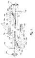
- an apparatus particularly for manufacturing electrical cables with a sheathing made of silicone rubber and the like, according to the invention is generally designated by the reference numeral 10.
- the apparatus 10 comprises a catalysis oven 11, which has a predominantly longitudinal extension and has mutually opposite access openings that are described in detail hereinafter.
- the apparatus further comprises means 12a and 12b for unwinding a conductor, made for example of copper, from a reel, means 13a and 13b for extruding insulating sheathing material, for example silicone rubber, onto said conductor, means 14a and 14b for tensioning the outgoing cable and means 15a and 15b for winding said cable onto a reel that are arranged functionally upstream and downstream of each one of the access openings, in order to make two cables 16 and 17 being treated slide with a longitudinal orientation and with opposite directions inside the oven 11.
- a conductor made for example of copper
- means 13a and 13b for extruding insulating sheathing material, for example silicone rubber
- the unwinding means 12a and 12b, the extrusion means 13a and 13b, the tensioning means 14a and 14b and the winding means 15a and 15b are shown schematically, since they are of a kind that is already known in the background art.
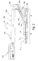
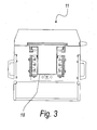
- the catalysis oven 11 comprises a tank for containing molten salts, which in turn comprises a central portion 18, which has a rectilinear longitudinal extension and inside which the cables 16 and 17 being treated are substantially parallel, and mutually opposite end portions 19 and 20, which form the access openings and inside which respective inlet portions 16a and 17a and outlet portions 16b and 17b of the two cables 16 and 17 being treated slide, as shown in Figures 1 and 2.
- the end portions 19 and 20 respectively comprise a first rectilinear portion 19a and 20a for the entry of the cables 16 and 17 being treated, which is aligned with the central portion 18 of the tank, and a second portion 19b and 20b for the exit of the cables 17 and 16 being treated, which is inclined with respect to the direction of longitudinal extension of the corresponding first portion 19a and 20a.
- Each one of the end portions 19 and 20 supports, with a rotary coupling, a corresponding pulley 21a and 21b for guiding the cables 16 and 17 being treated from the direction of the rectilinear extension of the central portion 18 to the direction of the longitudinal extension of the corresponding second portion 19b and 20b.
- the second portion 19b and 20b is inclined with respect to the direction of the longitudinal extension of the corresponding first portion 19a and 20a substantially by an angle of 30 sexagesimal degrees.
- the apparatus 10 further comprises, downstream of each second portion 19b and 20b, on a corresponding supporting structure 22a and 22b, a wheel 23a and 23b for guiding the corresponding outgoing cable 16 and 17, within the longitudinal dimensions of the oven 11, toward the tensioning means 14a and 14b and the winding means 15a and 15b in a direction that is substantially parallel to the central portion 18.
- the tensioning means 14a and 14b and the winding means 15a and 15b are arranged within the longitudinal dimensions of the oven 11.
- the apparatus 10 further comprises cleaning and drying means 24a and 24b of a per se known type for the outgoing cable 16 and 17; such means are arranged on the corresponding supporting structures 22a and 22b, downstream of the second portion 19b and 20b, and upstream of the guiding wheel 25a and 25b.
- marking means 25a and 25b and talc application means 26a and 26b Downstream of the guiding wheels 23a and 23b there are, in succession, marking means 25a and 25b and talc application means 26a and 26b for marking and applying talc to the corresponding cables 16 and 17 before they pass through the tensioning means 14a and 14b and the winding means 15a and 15b.
- the end portions 19 and 20 are mutually opposite with respect to the transverse and longitudinal planes of the central portion 18; in this manner, the longitudinal dimensions of the apparatus 10 are determined solely by the oven 11, by the unwinding means 12a and 12b and by the extrusion means 13a and 13b.
- the electrical cables 16 and 17 being treated constituted by a conductor sheathed with insulating material made of activated silicone rubber, enter the oven 11 respectively at the end portions 19 and 20, and exit from it respectively from the end portions 20 and 19.
- the apparatus 10 is capable of treating cable pairs having the same diameter or different diameters.
- the apparatus 10 can be associated with a safety device that is capable of interrupting its operation if one of the two cables breaks.
- An apparatus has in fact been provided which allows to compensate for the reduction in the level of the bath of molten salts, allowing to utilize the catalysis oven along its entire length.
- the apparatus allows to increase production capacity, which is practically twice that of a conventional apparatus with a catalysis oven of the same length, doubling the work space and reducing the logistic and personnel costs.
- the apparatus has a simple structure.
- the materials may be any according to requirements.
Landscapes
- Engineering & Computer Science (AREA)
- Manufacturing & Machinery (AREA)
- Extrusion Moulding Of Plastics Or The Like (AREA)
Applications Claiming Priority (2)
| Application Number | Priority Date | Filing Date | Title |
|---|---|---|---|
| ITPD20020118 ITPD20020118A1 (it) | 2002-05-09 | 2002-05-09 | Attrezzatura particolarmente per la realizzazione di cavi elettrici con rivestimento in gomma di silicone e simili |
| ITPD20020118 | 2002-05-09 |
Publications (2)
| Publication Number | Publication Date |
|---|---|
| EP1361584A2 true EP1361584A2 (de) | 2003-11-12 |
| EP1361584A3 EP1361584A3 (de) | 2004-01-14 |
Family
ID=29227562
Family Applications (1)
| Application Number | Title | Priority Date | Filing Date |
|---|---|---|---|
| EP03008837A Withdrawn EP1361584A3 (de) | 2002-05-09 | 2003-04-25 | Appareil, notamment pour fabriquer des câbles électriques avec revêtement en caoutchouc silicone et similaire |
Country Status (2)
| Country | Link |
|---|---|
| EP (1) | EP1361584A3 (de) |
| IT (1) | ITPD20020118A1 (de) |
Cited By (3)
| Publication number | Priority date | Publication date | Assignee | Title |
|---|---|---|---|---|
| EP1681684A3 (de) * | 2005-01-13 | 2007-06-13 | CET Electric S.r.l. | Vorrichtung zur herstellung elektrische kabel mit einer umhullung von siliconkunststoffen und ahnlichen materialien |
| CN101783210B (zh) * | 2009-12-09 | 2011-08-10 | 九川(浙江)科技股份有限公司 | 铜包铝排制造用清洗干燥一体化设备 |
| CN104575877A (zh) * | 2014-12-26 | 2015-04-29 | 国家电网公司 | 一种电缆干燥除水装置 |
Family Cites Families (2)
| Publication number | Priority date | Publication date | Assignee | Title |
|---|---|---|---|---|
| DE2204655C3 (de) * | 1972-01-28 | 1982-03-04 | Siemens AG, 1000 Berlin und 8000 München | Verfahren zur Herstellung von elektrischen Kabeln oder Leitungen mit einer Umhüllung und/oder Isolierung auf der Basis eines vernetzten Polyäthylens |
| DE2814503A1 (de) * | 1978-03-31 | 1979-10-04 | Siemens Ag | Verfahren und vorrrichtung zum aufbringen einer vernetz- und vulkanisierbaren kunststoffisolierung |
-
2002
- 2002-05-09 IT ITPD20020118 patent/ITPD20020118A1/it unknown
-
2003
- 2003-04-25 EP EP03008837A patent/EP1361584A3/de not_active Withdrawn
Cited By (3)
| Publication number | Priority date | Publication date | Assignee | Title |
|---|---|---|---|---|
| EP1681684A3 (de) * | 2005-01-13 | 2007-06-13 | CET Electric S.r.l. | Vorrichtung zur herstellung elektrische kabel mit einer umhullung von siliconkunststoffen und ahnlichen materialien |
| CN101783210B (zh) * | 2009-12-09 | 2011-08-10 | 九川(浙江)科技股份有限公司 | 铜包铝排制造用清洗干燥一体化设备 |
| CN104575877A (zh) * | 2014-12-26 | 2015-04-29 | 国家电网公司 | 一种电缆干燥除水装置 |
Also Published As
| Publication number | Publication date |
|---|---|
| ITPD20020118A1 (it) | 2003-11-10 |
| EP1361584A3 (de) | 2004-01-14 |
Similar Documents
| Publication | Publication Date | Title |
|---|---|---|
| US3507108A (en) | Method of producing s-z alternating twists and the apparatus therefor | |
| US4100721A (en) | Apparatus for twisting insulated conductors for use in multiconductor communication cable into quads | |
| CN205650612U (zh) | 一种铜丝放线拉丝装置 | |
| LU500601B1 (en) | Production apparatus for multilayered strand steel wire rope | |
| EP1361584A2 (de) | Appareil, notamment pour fabriquer des câbles électriques avec revêtement en caoutchouc silicone et similaire | |
| CN213230906U (zh) | 一种金刚线多线加工生产线 | |
| CN100370557C (zh) | 绝缘线生产线 | |
| CN118448115A (zh) | 无溅锡直焊性聚氨酯漆包线、生产装置与工艺 | |
| RU2123968C1 (ru) | Способ направления и разворота стальной ленты при прохождении через установку для непрерывной обработки (варианты) и устройство для его осуществления | |
| HK1061466A (en) | Apparatus particularly for manufacturing electrical cables with sheathing made of silicone rubber and the like | |
| FI90697B (fi) | Menetelmä ja sovitelma vaihtosuuntakertauksen yhteydessä | |
| CN201031098Y (zh) | 新型摇绞纱机导纱装置 | |
| CN217231262U (zh) | 一种基于双捻机的钢绳生产设备 | |
| DE1685842B2 (de) | Einrichtung zum Verseilen von Einzelsträngen mit reversierendem Schlag | |
| CN211237825U (zh) | 一种高速绞线机 | |
| CN204608496U (zh) | 超大型立式转锭绳机 | |
| JP2012214838A (ja) | 線材の表面処理装置 | |
| CN119340036A (zh) | 一种电缆加工用绞丝设备 | |
| CN213232537U (zh) | 金刚线加工多线上砂装置 | |
| WO2013117269A1 (en) | Multi-wire plating line at various levels | |
| SU860712A1 (ru) | Канатовьюща машина | |
| CN211142129U (zh) | 一种镀锡铜包钢线生产线 | |
| GB251661A (en) | Process and machine for making wire strands, ropes or cables | |
| US4356846A (en) | Apparatus for stranding multi-layer cable | |
| CN115538199B (zh) | 一种基于双捻机的钢绳生产设备及其应用方法 |
Legal Events
| Date | Code | Title | Description |
|---|---|---|---|
| PUAI | Public reference made under article 153(3) epc to a published international application that has entered the european phase |
Free format text: ORIGINAL CODE: 0009012 |
|
| AK | Designated contracting states |
Kind code of ref document: A2 Designated state(s): AT BE BG CH CY CZ DE DK EE ES FI FR GB GR HU IE IT LI LU MC NL PT RO SE SI SK TR |
|
| AX | Request for extension of the european patent |
Extension state: AL LT LV MK RO SI |
|
| PUAL | Search report despatched |
Free format text: ORIGINAL CODE: 0009013 |
|
| AK | Designated contracting states |
Kind code of ref document: A3 Designated state(s): AT BE BG CH CY CZ DE DK EE ES FI FR GB GR HU IE IT LI LU MC NL PT RO SE SI SK TR |
|
| AX | Request for extension of the european patent |
Extension state: AL LT LV MK RO SI |
|
| 17P | Request for examination filed |
Effective date: 20040608 |
|
| REG | Reference to a national code |
Ref country code: HK Ref legal event code: DE Ref document number: 1061466 Country of ref document: HK |
|
| AKX | Designation fees paid |
Designated state(s): AT BE BG CH CY CZ DE DK EE ES FI FR GB GR HU IE IT LI LU MC NL PT RO SE SI SK TR |
|
| 17Q | First examination report despatched |
Effective date: 20070727 |
|
| GRAP | Despatch of communication of intention to grant a patent |
Free format text: ORIGINAL CODE: EPIDOSNIGR1 |
|
| STAA | Information on the status of an ep patent application or granted ep patent |
Free format text: STATUS: THE APPLICATION IS DEEMED TO BE WITHDRAWN |
|
| 18D | Application deemed to be withdrawn |
Effective date: 20081101 |
|
| REG | Reference to a national code |
Ref country code: HK Ref legal event code: WD Ref document number: 1061466 Country of ref document: HK |