EP1361432B1 - Verfahren und Vorrichtung zur Bestimmung die Sauberkeit von Metal - Google Patents
Verfahren und Vorrichtung zur Bestimmung die Sauberkeit von Metal Download PDFInfo
- Publication number
- EP1361432B1 EP1361432B1 EP03016565A EP03016565A EP1361432B1 EP 1361432 B1 EP1361432 B1 EP 1361432B1 EP 03016565 A EP03016565 A EP 03016565A EP 03016565 A EP03016565 A EP 03016565A EP 1361432 B1 EP1361432 B1 EP 1361432B1
- Authority
- EP
- European Patent Office
- Prior art keywords
- metal
- metallic inclusions
- crucible
- levitation
- metallic
- Prior art date
- Legal status (The legal status is an assumption and is not a legal conclusion. Google has not performed a legal analysis and makes no representation as to the accuracy of the status listed.)
- Expired - Lifetime
Links
Images


Classifications
-
- G—PHYSICS
- G01—MEASURING; TESTING
- G01N—INVESTIGATING OR ANALYSING MATERIALS BY DETERMINING THEIR CHEMICAL OR PHYSICAL PROPERTIES
- G01N33/00—Investigating or analysing materials by specific methods not covered by groups G01N1/00 - G01N31/00
- G01N33/20—Metals
- G01N33/205—Metals in liquid state, e.g. molten metals
-
- G—PHYSICS
- G01—MEASURING; TESTING
- G01N—INVESTIGATING OR ANALYSING MATERIALS BY DETERMINING THEIR CHEMICAL OR PHYSICAL PROPERTIES
- G01N33/00—Investigating or analysing materials by specific methods not covered by groups G01N1/00 - G01N31/00
- G01N33/20—Metals
-
- G—PHYSICS
- G01—MEASURING; TESTING
- G01N—INVESTIGATING OR ANALYSING MATERIALS BY DETERMINING THEIR CHEMICAL OR PHYSICAL PROPERTIES
- G01N23/00—Investigating or analysing materials by the use of wave or particle radiation, e.g. X-rays or neutrons, not covered by groups G01N3/00 – G01N17/00, G01N21/00 or G01N22/00
- G01N23/22—Investigating or analysing materials by the use of wave or particle radiation, e.g. X-rays or neutrons, not covered by groups G01N3/00 – G01N17/00, G01N21/00 or G01N22/00 by measuring secondary emission from the material
- G01N23/223—Investigating or analysing materials by the use of wave or particle radiation, e.g. X-rays or neutrons, not covered by groups G01N3/00 – G01N17/00, G01N21/00 or G01N22/00 by measuring secondary emission from the material by irradiating the sample with X-rays or gamma-rays and by measuring X-ray fluorescence
-
- G—PHYSICS
- G01—MEASURING; TESTING
- G01N—INVESTIGATING OR ANALYSING MATERIALS BY DETERMINING THEIR CHEMICAL OR PHYSICAL PROPERTIES
- G01N33/00—Investigating or analysing materials by specific methods not covered by groups G01N1/00 - G01N31/00
- G01N33/20—Metals
- G01N33/202—Constituents thereof
- G01N33/2022—Non-metallic constituents
-
- G—PHYSICS
- G01—MEASURING; TESTING
- G01N—INVESTIGATING OR ANALYSING MATERIALS BY DETERMINING THEIR CHEMICAL OR PHYSICAL PROPERTIES
- G01N33/00—Investigating or analysing materials by specific methods not covered by groups G01N1/00 - G01N31/00
- G01N33/20—Metals
- G01N33/204—Structure thereof, e.g. crystal structure
- G01N33/2045—Defects
-
- Y—GENERAL TAGGING OF NEW TECHNOLOGICAL DEVELOPMENTS; GENERAL TAGGING OF CROSS-SECTIONAL TECHNOLOGIES SPANNING OVER SEVERAL SECTIONS OF THE IPC; TECHNICAL SUBJECTS COVERED BY FORMER USPC CROSS-REFERENCE ART COLLECTIONS [XRACs] AND DIGESTS
- Y10—TECHNICAL SUBJECTS COVERED BY FORMER USPC
- Y10T—TECHNICAL SUBJECTS COVERED BY FORMER US CLASSIFICATION
- Y10T436/00—Chemistry: analytical and immunological testing
- Y10T436/20—Oxygen containing
-
- Y—GENERAL TAGGING OF NEW TECHNOLOGICAL DEVELOPMENTS; GENERAL TAGGING OF CROSS-SECTIONAL TECHNOLOGIES SPANNING OVER SEVERAL SECTIONS OF THE IPC; TECHNICAL SUBJECTS COVERED BY FORMER USPC CROSS-REFERENCE ART COLLECTIONS [XRACs] AND DIGESTS
- Y10—TECHNICAL SUBJECTS COVERED BY FORMER USPC
- Y10T—TECHNICAL SUBJECTS COVERED BY FORMER US CLASSIFICATION
- Y10T436/00—Chemistry: analytical and immunological testing
- Y10T436/25—Chemistry: analytical and immunological testing including sample preparation
- Y10T436/25375—Liberation or purification of sample or separation of material from a sample [e.g., filtering, centrifuging, etc.]
Definitions
- the present invention relates to an evaluation apparatus for cleanliness of a metal which quickly discharges non-metallic inclusions contained in a steel, for example, to the surface portion, detects the non-metallic inclusions accumulating the surface either chemically or physically, and accurately determines the proportion of the non-metallic inclusions in the metal as a total quantity evaluation or as an evaluation of principal components in accordance with a particle size distribution.
- Non-metallic inclusion particles existing in the steel include alumina type inclusions formed as the result of the reaction between oxygen in the steel and aluminum added in the case of an aluminum killed steel, slag type inclusions containing lime/silica, etc., and resulting from a steel making slag, powder type inclusions resulting from a casting mold lubricant in continuous casting, and so forth. Since these inclusions result in defects such as flows and breakage in intermediate products, during rolling of thin sheets, wire materials, etc., or in final products, evaluation of these inclusions by various methods have bean carried out in the past for the purpose of quality control.
- the evaluation technology of the inclusions of the steel among the metals is described, for example, in " Steel Handbook, 3rd Edition", II Pig Iron & Steel Making (edited by Japan Iron & Steel Institute of Japan, - published by Maruzen, October 15, 1979 ).
- Examples of the evaluation methods include a total oxygen (T[O]) method based on the oxygen concentration in the steel, a slime method by electrolytic extraction used for evaluating large inclusions, a microscopic method for evaluating the inclusions by magnifying and observing the section of a metal, and so forth. Due to their respective features, these technologies are limited by the kind of inclusions as the investigation object and the sizes of the inclusions as tabulated in Table 1, and they are not free from the problem, either, that a long time is necessary depending on the evaluation method.
- the conventional means involves the problems that the evaluation sample does not sufficiently represent the quality of the intermediate product and a long time is necessary for the evaluation of the sample, and those methods which invite excessively great super-heat during melting such as an EB (electron beam melting) method involve the problem that the inclusions are denatured during evaluation.
- EB electron beam melting
- the slime method has been widely employed as a method having relatively high accuracy, but an extremely long time of several days to dozens of days is necessary to electrolyze about 1 kg sample as a whole.
- Table 1 name particle diameter of inclusions evaluation quantity & necessary time others microscope up to 40 ⁇ m 100 positions, 25 mm 2 several days T[O] - - slime at least 40 ⁇ m several kg, several to dozens of days EB up to 200 ⁇ m 2g (several pcs) one day components evaporate due to reduced pressure
- This invention not limited hundred to thousand grams, about 10 min. components do not evaporate due to Ar atmospheric pressure
- the melting means is different from the EB method
- an induction melting extraction method using a cold crucible method is conceivable as the same melting extraction method.
- this method eliminates the problems such as high temperature melting of the EB method and the resulting modification of the inclusions, and insufficiency as the representative value by the evaluation volume of the small amount.
- a method of measuring the inclusions of the surface of the sample produced by this cold crucible levitation-melting method is described, for example, in " Evaluation of Alloy Cleanness in Superclean Materials", K.C. Mills et al., Turkdogan Symposium Proceedings, pp. 105-112 (1994 ).
- the method of this reference inspects the surface inclusions by a scanning electron microscope.
- this reference points out only the problem as the evaluation method by the characteristics of the cold crucible itself, but does not teach the method of evaluating the non-metallic inclusions over a wide area of the metal surface industrially, economically and quickly.
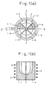
- Figs. 1(a) and 1(b) are explanatory views of the principal portions of a cold crucible apparatus, wherein Fig. 1(a) is an explanatory plan view, and Fig. 1(b) is an explanatory view of the longitudinal section taken along A - A of Fig. 1(a) .
- reference numerals (1 - 1, ..., 1 - 8) denote eight, for example, copper segments which together form a crucible and the inside of which is cooled with water. They are disposed adjacent to one another with the gap slits 3 interposed at a plurality of substantially equidistant positions and form the crucible.
- Reference numeral 2 in the drawings denotes an induction coil, which is so disposed as to encompass the crucible.
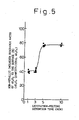
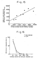
- Fig. 5 is a diagram showing the relation between an alumina discharge ratio in the sample and a levitation-melting retention time.
- a sample of a weight of dozens of grams to several kilo-grams is levitation-melted by the cold crucible levitation-melting method, and according to the result of the experiments by using a metal piece of 100g, it can be seen from Fig. 5 that about 80% of the non-metallic inclusions in the sample are discharged when melting is retained for at least 3 minutes and the discharge ratio does not alter even when the melting retention time is kept longer than 3 minutes.
- Figs. 7(a) and (b) are schematic views useful for explaining the movement of the non-metallic inclusions discharged to the surface of the levitation-melted metal in the conventional cold crucible method which applies an ordinary single-phase radio frequency current to an induction coil.
- Fig. 7(a) in an explanatory view when the current is applied and
- Fig. 7(b) is an explanatory view when the high frequency current is cut off.
- a gentle stream 10 of the melted metal which rises at the center and flows down along the surface is formed in the levitation-melted metal.
- a part 9-1 of the non-metallic inclusions discharged to the surface of the molten metal is pushed by this stream 10 of the molten metal and moves to the gap between the levitation-melted metal 4 and the segments 1.
- the non-metallic inclusions 9-1 do not accumulate on the surface of the top of the molten metal but are pushed to the portion in the proximity of the lower surface of the molten metal as shown in Fig. 7(b) . Therefore, when cleanliness of the metal is evaluated in the case of Fig. 7(b) , the metal surface of the sample 4 in Fig. 7(b) after solidification is measured. However, because the non-metallic inclusions scatter on the surface and have a broad measurement area, convenience and quickness of the evaluation of non-metallic inclusions are not yet sufficient.
- the non-metallic inclusions according to the present method spout up around the axis of symmetry of the molten metal and are deposited between the sidewall and the molten metal while being carried by the stream that flows down along the wall of the crucible as shown in Fig. 7(a) .
- the current to the coil is cut off in this instance, the levitating metal is pushed to the bottom of the crucible due to the gravity as shown in Fig. 7(b) , and some of the non-metallic inclusions discharged to the surface are collected by the side portions of the metal while another part moves on the metal.
- the current is once held at a level at which the metal under levitating is solidified, and is then cut off after solidification of the metal, the non-metallic inclusions are collected only at the side portion and form a band-like accumulating band.
- Fig. 8 shows an induction heating coil for supplying high frequency currents of U, V and W of the three-phase alternating current having mutually different phases as the induction heating coil.
- This induction heating coil is so constituted as to possess the function of a linear motor for forming an upward stream 11 on the surface of the molten metal 4 which is levitation-melted by the three-phase AC Currents, U, V and W.
- the high frequency currents U, V and W are so arranged as to allow the metal sample 4 to be levitation-melted.
- the induction heating coil levitation-melts the metal sample 4 and forms the upward stream 11 on the surface of the molten metal which is so levitation-melted.
- the stream becomes upward along the wall of the crucible during melting, too, as shown in Fig. 8 . Therefore, the non-metallic inclusions accumulate only at the upper portion, and accumulate at the upper portion, even after solidification, irrespective of the cut-off operation of the current. Consequently, substantially all of the non-metallic inclusions contained in the metal sample can be determined by measuring the non-metallic inclusions of the island-like occupation area at the top of the molten metal, and cleanliness of the metal can be evaluated extremely conveniently and quickly.
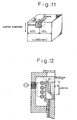
- Twenty cast slabs of low carbon aluminum killed steels were first cast by using a casting mold having a width of 1,500 mm and a thickness of 250 mm at a casting rate of 1.2 m/min. Samples were collected at 1/4 and 1/2 portions from a size of 20 mm in the casting direction, 30 mm from the surface layer in the thickness direction and 20 mm in the transverse direction from these slabs, respectively. Each sample was melted in a crucible having an inner diameter of 40 mm, a depth of 40 mm and a parabolic sectional shape within the range of 20 mm to 40 mm from the upper end shown in Fig. 12 in an atmosphere having a gauge pressure of 0.2 atms with respect to the atmospheric pressure.
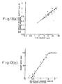
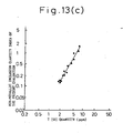
- Fig. 13(a) shows the result of their indices and this diagram shows, a very close correlationship.
- Fig. 13(b) shows the index comparison with a defect index of a product sheet after rolling and surface treatment of the same slab, and a close correlationship could be obtained.
- Slabs of a high carbon steel were first cast by a 160 mm-square casting mold at a casting rate of 2 m/min, and each sample was collected at a 1/2 portion of the side of each slab from a size of 20 mm in the casting direction, 30 mm from the surface layer in the thickness direction and 20 mm in a peripheral direction as shown in Fig. 11 .
- Each sample was melted in a crucible having an inner diameter of 40 mm, a depth of 40 mm and a parabolic sectional shape within the range of 20 mm to 40 mm from the upper end as shown in Fig. 12 in an atmosphere having a gauge pressure of 0.2 atm with respect to the atmospheric pressure.
- Table 2 shows the estimated particle diameters by the statistical extremes and the particle diameters of the maximum non-metallic inclusions on the surface of the fifty samples. A result substantially coincide with the estimated particle diameters could be obtained.
- Twenty cast slabs of a low carbon aluminum killed steel were first cast by using a casting mold having a width of 1,500 mm and a thickness of 250 mm at a casting rate of 1.2 m/min, and samples were collected at 1/4 and 1/2 portions in the transverse direction of the slabs from a size of 20 mm in the casting direction, 30 mm from the surface layer in the thickness direction and 20 mm in the transverse direction.
- Each sample was melted in a crucible having an inner diameter of 40 mm, a depth of 40 mm and a parabolic sectional shape within the range of 20 mm to 40 mm from the upper end as shown in Fig. 12 in an Ar atmosphere at atmospheric pressure. The sample was held for 5 minutes after melting, and was solidified after discharging the non-metallic inclusions.
- Twenty slabs of a low carbon aluminum killed steel were first cast by using a casting mold having a width of 1,500 mm and a thickness of 250 mm at a casting rate of 1.2 m/min, and each sample was collected at 1/4 and 1/2 portions in the transverse direction of the slabs from a size of 20 mm in the casting direction, 30 mm from the surface layer in the thickness direction and 20 mm in the transverse direction.
- Each sample was melted in a crucible having an inner diameter of 40 mm, a depth of 40 mm and a parabolic sectional shape within the range of 20 mm to 40 mm from the upper end as shown in Fig. 12 in an Ar atmosphere at atmospheric pressure. The sample was held for 5 minutes after melting, and after the non-metallic inclusions were discharged, the sample was solidified.
- the residue on the filter was analyzed by the fluorescent X-ray analysis.
- An ultrasonic sieving method was employed as a method of measuring the particle size of oxides.
- the residue on the filter was dispersed in a methanol solution or an ethanol solution by using an ultrasonic wave. This solution was poured onto a filter having a suitable mesh and was filtrated and classified by applying ultrasonic vibration.
- the particle size distribution and the component composition of the non-metallic inclusions were determined by the weight of the residues and their chemical analysis values on the respective filters.
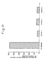
- Fig. 17 shows the results of the non-metallic inclusions contained in the sample inside the tundish and the non-metallic inclusions contained in the sample, and their comparison result.
- the evaluation method of the present invention could evaluate economically, quickly and conveniently the non-metallic inclusions in the steel samples to find out, for example, that the quantity of the non-metallic inclusions was great in the tundish and was small in the slabs.
- the solidified body having the non-metallic inclusion particles accumulating on the surface thereof was set as an anode to a 10% acetylacetone type electrolyte solution, and was electrolyzed to a weight of 0.5g with the impurity particles on the surface of the solidified body at a current density of 5 to 50 mA/cm 2 . Thereafter, the electrolyte solution was filtrated, and the residue on the filter was dispersed by the ultrasonic sieving method and was then poured onto a metallic filter having meshes of desired sizes to as to conduct filtration and classification by applying ultrasonic vibration.
- the experiment was conducted three times for a continuous cast slab of the same charge, that is, the case where the retention time was 60 seconds, 120 seconds and 180 seconds.
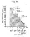
- the non-metallic inclusion particles were classified into the following eight kinds in accordance with their sizes, that is, the first kind (exceeding 300 ⁇ m), the second kind (250 to 300 ⁇ m), the third kind (200 to less than 250 ⁇ m), the fourth kind (150 to less than 200 ⁇ m), the fifth kind (100 to less than 150 ⁇ m), the sixth kind (50 to less than 100 ⁇ m), the seventh kind (10 to less than 50 ⁇ m) and the eighth kind (less than 10 ⁇ m).
- Fig. 19 shows the results of the experiments.
- the retention time t at which the five kinds of non-metallic inclusion particles having the sizes of 100 to 150 ⁇ m attained the maximum frequency was 60" in Fig. 18 but was 110" in Fig. 19 .
- the retention time at which the seven kinds of the non-metallic inclusion particles having the sizes of 10 to 50 ⁇ m attained the maximum frequency was 120" in Fig. 18 , but was 220" in Fig. 19 .
- the retention time of the levitation-melted metal was adjusted by using t/ ⁇ (30 d). This adjustment made it possible to correctly grasp the non-metallic inclusion particles even when a crucible having different size was used, and made it also possible to directly compare the results of the measurements of the non-metallic inclusion particles carried out by using crucibles having mutually different sizes.
- the present example collected the samples from continuous cast slabs different from those of Fig. 18 and conducted the experiments by using a cold crucible having a maximum inner diameter of 30 mm by changing the retention time of the levitation-melted metal to 60 seconds, 120 seconds and 180 seconds.
- the impurity particles gathered on the surface of the levitation-melted metal were processed and classified in the same way as in Fig. 18 .
- Fig. 20 shows the results of these experiments. Since the continuous cast slabs having a different charge from those shown in Fig. 18 were used in Fig. 20 , the numbers of non-metallic inclusion particles were different from those in Fig. 18 . However, the number of kinds of the sizes of the non-metallic inclusion particles occurring at the maximum frequency when t/ ⁇ (30 d) was 2 was five kinds in the same way as in Fig. 18 , the number of kinds of the non-metallic inclusion particles at the maximum frequency was seven kinds in the same way as in Fig. 18 when t/ ⁇ (30 d) was 4, and the number of kinds of the non-metallic inclusion particles at the maximum frequency was eight kinds in the same way as in Fig. 18 when t/ ⁇ (30 d) was 6.
- non-metallic inclusion particles of the first to fifth kinds mostly gathered on the surface of the molten metal at t/ ⁇ (30 d) of 2 in Fig. 20 in the same way as in Fig. 18 , and their number hardly increased even when t/ ⁇ (30 d) was increased to 4 or 6.
- the non-metallic inclusions particles having medium sizes of the sixth to seventh kinds did not sufficiently accumulated on the surface of the molten metal at t/ ⁇ (30 d) of 2, but mostly gathered on the surface of the molten metal at t ⁇ (30 d) of 4 and hardly increased thereafter even when t/ ⁇ (30 d) was set to 6.
- the present example measured the quantity N pcs/kg of the non-metallic inclusion particles having seven kinds of L.
- the quantities N 1 , N 2 , ... , N 7 of the first to seventh kinds of non-metallic inclusion particles having L of at least 7 were measured.
- the continuous cast slabs were subjected to plastic working to obtain steel products.
- the non-metallic inclusion particles invited the occurrence of defects such as scratches during the production process of the steel material and the steel products, and invited also defects in quality such as the reduction of service life of the steel products.
- the sizes of the non-metallic inclusion particles that invited the occurrence of defects such as flaws and defects in quality changed, as well.
- the cold crucible treatment was carried out by setting t/ ⁇ (30 d) to 4, for example, and cleanliness of the metal could be evaluated by measuring the quantity N pcs/kg of the seven kinds of non-metallic inclusion particles.
- the cold crucible treatment was carried out by setting t/ ⁇ (30 d) to 4, for example, and cleanliness of the metal could be evaluated by measuring the quantity N pcs/kg of the seven kinds of non-metallic inclusion particles.
- measurement of cleanliness of the metal could be simplified and could be made easier than the prior art method.
- Samples were collected from continuous cast slabs of low carbon aluminum killed steels having three different kinds of charges and a thickness of 250 mm, and each of the samples was levitation-melted by using a cold crucible having a maximum inner diameter of 30 mm in an Ar atmosphere at atmospheric pressure.
- the levitation-melted metal was retained for 120 seconds so as to gather the non-metallic inclusions on the surface of the levitation-melted metal, and then the high frequency current applied to the coil of the cold crucible was cut off. Ten and fifteen seconds later from cut-off of the high frequency current, the upper surface of the metal inside the crucible was photographed by a CCD camera.
- Each metal sample having the non-metallic inclusions accumulating on the surface thereof inside the crucible was photographed by the CCD camera, and was taken out from the crucible after solidification. After the areas of the occupying portions of the island-like non-metallic inclusions were measured at normal temperature, the metal sample was set as an anode into a 10% acetyl-acetone type electrolyte solution, and the metal surface was electrolyzed to a weight of 0.5g at a current density of 5 to 50 mA/cm 2 . After filtration, the weight of the non-metallic inclusions was measured.
- the images so obtained were subjected to image processing in the same way as when the crucible had the maximum inner diameter of 30 mm, and the areas of the occupying portions of the island-like non-metallic inclusions were determined.
- the metal having the non-metallic inclusions gathering on the surface thereof inside the crucible was subjected to measurement of the occupying areas of the island-like non-metallic inclusions in the same way as when the crucible had the maximum inner diameter of 30 mm, and then the surface of the metal was electrolyzed to a weight of 1g so as to measure the weight of the non-metallic inclusions. Table 3 shows the results of these experiments. Table 3 No.
- the retention time t of the levitation-melted metal was preferably limited to the range of 1 ⁇ t/ ⁇ (30 d) ⁇ 20.
- Figs. 7(a) and (b) are explanatory views useful for explaining the movement of the non-metallic inclusions gathering on the surface of the levitation-melted metal.
- Fig. 7(a) is a schematic view when the high frequency current was caused to flow through the coil to hold the levitation-melted metal. In this case, a gentle stream 10 of the molten metal which rose at the center and flowed along the surface was formed inside the molten metal 4 that was levitated. Due to this stream 10 of the molten metal, the non-metallic inclusions 9 gathering on the surface of the molten metal were caused to flow towards the segments 1 and moved towards them.
- the metal sample that was cooled to room temperature was set as an anode into a 10% acetylacetone type electrolyte solution, and the metal surface was electrolyzed at a current density of 5 to 50 mA/cm 2 .
- the metal surface on the top side of the levitation-melted metal was electrolyzed as the first step, and then the whole metal surface was electrolyzed as the second step.
- the solution used for this electrolysis was filtrated, and the non-metallic inclusions were fractioned and their weight was measured.
- the second step could be omitted, and the quantity of the non-metallic inclusions could be measured more quickly and more easily than in the prior art methods.
- the quantity of the non-metallic inclusions extracted by electrolysis of the first step was about 60%, and the second step was essentially necessary.
- samples were collected from continuous cast slabs of three low carbon aluminum killed steels having mutually different charges, and levitation-melted them by the apparatus having the three-phase A.C. induction heating coil. After each sample was held under the levitation-melted state for about 10 seconds, the supply of power was stopped, and the top portion of each metal sample during cooling was photographed by the CCD camera. Because luminance of the metal during cooling was different from that of the non-metallic inclusions, an image wherein the island-like occupying zones of the non-metallic inclusions were formed at the center could be obtained in each case. The area of the occupying zones of the non-metallic inclusions was measured by processing the image so obtained.
- each sample molten by the cold crucible was analyzed by fluorescent X-rays. Measurement was carried out at a primary X-ray intensity of 1 ⁇ A ⁇ 50 kV and an irradiation time of 90 seconds. Existence indexes of alumina, silicate, calcia, etc., were determined from the fluorescent X-ray intensity of Al, Si, Ca, etc.
- Measurement plane 1 Alumina index Calcia index This Invention Comparative Example This Invention Comparative Example 1 Measurement plane 1 4.0 0.003 2 6.3 0.006 3 13.1 0.007 4 7.1 0.006 8.2 mean 7.6 0.005 mean 0.006 2 Measurement plane 1 10.1 0.007 2 21.0 0.002 3 13.7 0.003 4 4.9 0.002 11.7 mean 12.4 0.006 mean 0.006 3 Measurement plane 1 mean 18.4 0.328 2 16.8 0.750 3 4.6 0.157 4 4.4 0.071 11.5 mean 11.0 0.339 mean 0.326 4 Measurement plane 1 33.2 0.677 2 20.2 0.210 3 17.9 0.408 4 23.1 0.682 25.4 mean 23.6 0.488 0.494
Landscapes
- Chemical & Material Sciences (AREA)
- Health & Medical Sciences (AREA)
- Life Sciences & Earth Sciences (AREA)
- Immunology (AREA)
- Analytical Chemistry (AREA)
- Biochemistry (AREA)
- General Health & Medical Sciences (AREA)
- General Physics & Mathematics (AREA)
- Physics & Mathematics (AREA)
- Pathology (AREA)
- Engineering & Computer Science (AREA)
- Food Science & Technology (AREA)
- Medicinal Chemistry (AREA)
- Crystallography & Structural Chemistry (AREA)
- Investigating And Analyzing Materials By Characteristic Methods (AREA)
- Sampling And Sample Adjustment (AREA)
- Analysing Materials By The Use Of Radiation (AREA)
Claims (5)
- Bewertungsvorrichtung für die Reinheit eines Metalls mit:einer Metallschwebeschmelzeinrichtung;wobei die Metallschwebeschmelzeinrichtung aufweist:einen wassergekühlten Metalltiegel (13) mit einer Bodenfläche, die eine Krümmung hat, und einer Seitenwandfläche, die eine schräge Oberfläche hat, die sich nach oben allmählich aufweitet, und mit in Radialrichtung eingefügten Schlitzen sowie mehreren in Umfangsrichtung unterteilten Segmenten (1) und mit einer offenen Oberseite undeiner geschlossenen Unterseite;einer Induktionsspule (2, 16) zum Erzeugen einer Abstoβung von der Seitenwandfläche des wassergekühlten Metalltiegels (13) in Mittenrichtung und Leiten eines Hochfrequenzstroms zum Schmelzen des Metalls, während das Metall in der Schwebe gehalten wird, die so angeordnet ist, dass sie den wassergekühlten Metalltiegel (13) umschließt; undeinem Behälter (11) zum Aufrechterhalten einer nicht oxidierenden Atmosphäre;dadurch gekennzeichnet, dass die Bewertungsvorrichtung ferner aufweist:eine Säurelösungs- oder Elektrolysiereinrichtung zum Extrahieren nichtmetallischer Einschlüsse, die auf der Oberfläche des Metalls konzentriert sind, das durch die Metallschwebeschmelzeinrichtung geschmolzen und verfestigt wird, eine Filtereinrichtung zum Filtern der extrahierten nichtmetallischen Einschlüsse, eine Wiegeeinrichtung zum Wiegen der extrahierten nichtmetallischen Einschlüsse und eine Analysiereinrichtung einer Röntgenfluoreszenzanalyse zum Analysieren der extrahierten, gefilterten und gewogenen nichtmetallischen Einschlüsse.
- Bewertungsvorrichtung für die Reinheit eines Metalls nach Anspruch 1, wobei die Bewertungsvorrichtung aufweist: eine Einrichtung zum Führen eines Dreiphasen-Hochfrequenz-Wechselstroms durch die Induktionsspule (2, 16) zum Bewirken einer Abstoßung, die sich auf der Oberfläche einer Metallschmelze entlang der Wand des Tiegels (13) nach oben bewegt, während das Metall darin in Schwebe gehalten und geschmolzen wird.
- Bewertungsvorrichtung für die Reinheit eines Metalls nach Anspruch 1 oder 2, wobei die Bewertungsvorrichtung aufweist: eine Einrichtung zum Zuführen eines durch die Induktionsspule (2, 16) zu leitenden Stroms, bei der es sich um eine Einphasen-Wechselstromquelle handelt.
- Bewertungsvorrichtung für die Reinheit eines Metalls nach einem der Ansprüche 1 bis 3, wobei die Form der Innenfläche des Tiegels eine Form hat, die durch Schneiden eines Rotationskörpers mit der Symmetrieachse einer senkrechten Achse in Hälften auf einer Symmetrieebene gebildet ist, sowie eine Form, die durch eine obere Form eines Kreiskegelstumpfs mit der gleichen Form wie die der Symmetrieebene oder eine nach oben aufgeweitete ähnliche Form der waagerechten Schnittform gebildet ist.
- Bewertungsvorrichtung für die Reinheit eines Metalls nach einem der Ansprüche 1 bis 3, wobei die Bodenfläche des Tiegels (13) so geformt ist, dass der Boden der Innenfläche in einem Bereich von mindestens 90 % des Durchmessers der Innenfläche zu einer ebenen Oberfläche wird.
Applications Claiming Priority (17)
| Application Number | Priority Date | Filing Date | Title |
|---|---|---|---|
| JP5481095 | 1995-03-14 | ||
| JP5481095 | 1995-03-14 | ||
| JP6659295 | 1995-03-24 | ||
| JP6659295 | 1995-03-24 | ||
| JP14245695 | 1995-05-18 | ||
| JP14245695 | 1995-05-18 | ||
| JP12178695 | 1995-05-19 | ||
| JP7121786A JPH1026618A (ja) | 1995-05-19 | 1995-05-19 | 金属中介在物の迅速評価方法 |
| JP1236996 | 1996-01-29 | ||
| JP1236996 | 1996-01-29 | ||
| JP1237096 | 1996-01-29 | ||
| JP1237096 | 1996-01-29 | ||
| JP2127396 | 1996-02-07 | ||
| JP2127396 | 1996-02-07 | ||
| JP2127296 | 1996-02-07 | ||
| JP2127296 | 1996-02-07 | ||
| EP96906022A EP0760480B1 (de) | 1995-03-14 | 1996-03-14 | Vorrichtung und verfahren zur bewertung der reinheit eines metalles |
Related Parent Applications (2)
| Application Number | Title | Priority Date | Filing Date |
|---|---|---|---|
| EP96906022A Division EP0760480B1 (de) | 1995-03-14 | 1996-03-14 | Vorrichtung und verfahren zur bewertung der reinheit eines metalles |
| EP96906022.7 Division | 1996-09-19 |
Publications (3)
| Publication Number | Publication Date |
|---|---|
| EP1361432A2 EP1361432A2 (de) | 2003-11-12 |
| EP1361432A3 EP1361432A3 (de) | 2004-11-17 |
| EP1361432B1 true EP1361432B1 (de) | 2012-02-22 |
Family
ID=27571720
Family Applications (2)
| Application Number | Title | Priority Date | Filing Date |
|---|---|---|---|
| EP03016565A Expired - Lifetime EP1361432B1 (de) | 1995-03-14 | 1996-03-14 | Verfahren und Vorrichtung zur Bestimmung die Sauberkeit von Metal |
| EP96906022A Expired - Lifetime EP0760480B1 (de) | 1995-03-14 | 1996-03-14 | Vorrichtung und verfahren zur bewertung der reinheit eines metalles |
Family Applications After (1)
| Application Number | Title | Priority Date | Filing Date |
|---|---|---|---|
| EP96906022A Expired - Lifetime EP0760480B1 (de) | 1995-03-14 | 1996-03-14 | Vorrichtung und verfahren zur bewertung der reinheit eines metalles |
Country Status (8)
| Country | Link |
|---|---|
| US (2) | US5985674A (de) |
| EP (2) | EP1361432B1 (de) |
| KR (1) | KR100229096B1 (de) |
| CN (1) | CN1112587C (de) |
| AU (1) | AU686498B2 (de) |
| CA (1) | CA2190123C (de) |
| DE (1) | DE69632614T2 (de) |
| WO (1) | WO1996028729A1 (de) |
Families Citing this family (20)
| Publication number | Priority date | Publication date | Assignee | Title |
|---|---|---|---|---|
| EP1361432B1 (de) * | 1995-03-14 | 2012-02-22 | Nippon Steel Corporation | Verfahren und Vorrichtung zur Bestimmung die Sauberkeit von Metal |
| JP3447516B2 (ja) | 1997-05-27 | 2003-09-16 | 新日本製鐵株式会社 | 非金属介在物分析用の金属サンプル作製方法及びその装置 |
| RU2149400C1 (ru) * | 1999-02-03 | 2000-05-20 | Открытое акционерное общество "Северсталь" | Способ контроля качества стальных изделий (его варианты) |
| US6590200B1 (en) * | 1999-04-02 | 2003-07-08 | Worcester Polytechnic Institute | Systems for detecting measuring inclusions |
| US6693443B2 (en) | 1999-04-02 | 2004-02-17 | Worcester Polytechnic Institute | Systems for detecting and measuring inclusions |
| KR100681663B1 (ko) | 2004-12-20 | 2007-02-09 | 재단법인 포항산업과학연구원 | X-선 현미경을 이용한 스테인레스 강판의 개재물 청정도평가방법 |
| US8530790B2 (en) * | 2005-09-12 | 2013-09-10 | Lincoln Global, Inc. | Method for extracting non-metallic weld metal inclusions |
| PL2270469T3 (pl) * | 2008-04-25 | 2020-11-16 | Nippon Steel Corporation | Sposób analizy dystrybucji wielkości cząstek w przypadku cząstek w materiale metalowym |
| JP4737278B2 (ja) * | 2008-11-28 | 2011-07-27 | Jfeスチール株式会社 | 金属材料中の析出物および/または介在物の分析方法 |
| JP5359244B2 (ja) * | 2008-12-17 | 2013-12-04 | Jfeスチール株式会社 | 金属試料中の析出物及び/又は介在物の分析方法 |
| DE102012109248A1 (de) * | 2012-09-28 | 2014-04-03 | Fluxana GmbH & Co. KG | Herstellung von Analyseproben |
| CN103123329B (zh) * | 2012-12-31 | 2015-07-29 | 上海大学 | 金属中非金属夹杂物的快速检测方法及快速检测装置 |
| CN105043098B (zh) * | 2015-07-09 | 2017-04-05 | 佛山市技新电气有限公司 | 一种电熔炉 |
| CN106872512A (zh) * | 2016-12-29 | 2017-06-20 | 中南大学 | 一种测试金属材料快速凝固行为及凝固热流的方法 |
| JP6992714B2 (ja) * | 2017-11-16 | 2022-01-13 | 住友金属鉱山株式会社 | 金属酸化物中における金属単体の定量方法 |
| CN110044763B (zh) * | 2019-05-06 | 2022-05-13 | 浙江福达合金材料科技有限公司 | 一种高纯银锭中硝酸不溶物含量的检测方法 |
| FR3114398B1 (fr) * | 2020-09-24 | 2025-12-12 | Commissariat Energie Atomique | Méthode d’analyse par spectroscopie de rayons X à dispersion d’énergie d’au moins une espèce chimique dans un bain de fusion ou un cordon solidifié produit par un procédé de fabrication additive ou de soudage d’un alliage métallique |
| IT202100031649A1 (it) * | 2021-12-17 | 2023-06-17 | Cogne Acciai Speciali S P A | Metodo per analisi chimica di elementi in leghe metalliche con separazione della componente metallica |
| CN114636802B (zh) * | 2022-02-16 | 2023-11-28 | 大冶特殊钢有限公司 | 一种冶炼过程中钢水纯净度的检测方法 |
| CN118134279B (zh) * | 2024-03-05 | 2025-02-18 | 鞍钢股份有限公司 | 锌液面渣聚合效果评价方法 |
Family Cites Families (25)
| Publication number | Priority date | Publication date | Assignee | Title |
|---|---|---|---|---|
| US3432753A (en) * | 1966-09-30 | 1969-03-11 | Gen Electric | Method of analyzing materials to determine the impurity content thereof |
| US3507144A (en) * | 1968-03-21 | 1970-04-21 | Westinghouse Electric Corp | Gas content analysis with a metal levitation system |
| JPS511235B2 (de) * | 1972-05-11 | 1976-01-14 | ||
| DE2549735A1 (de) * | 1975-11-06 | 1977-11-03 | G F Paul Mueller Ingenieur Bue | Vorrichtung und verfahren zur bestimmung von duennen fremdschichten und schichtdicken auf stoffen |
| FR2381303A1 (fr) * | 1977-02-21 | 1978-09-15 | Siderurgie Fse Inst Rech | Appareil pour la preparation automatique d'echantillons destines a l'analyse par fluorescence x |
| JPS58172596A (ja) * | 1982-04-05 | 1983-10-11 | 株式会社東芝 | 軽水炉接水部構造体の接水部表面処理方法 |
| FR2556095B1 (fr) * | 1983-12-02 | 1986-09-05 | Philips Ind Commerciale | Procede automatique de dosage d'echantillon et machine automatique pour doser et analyser |
| US4612042A (en) * | 1984-03-01 | 1986-09-16 | Stelco Inc. | Method for automatically fluxing and casting samples |
| USH135H (en) * | 1984-06-19 | 1986-09-02 | Electromagnetic levitation casting apparatus having improved levitation coil assembly | |
| US5257302A (en) * | 1987-08-31 | 1993-10-26 | Ngk Insulators, Ltd. | Fluorescent X-ray analyzing system |
| JPH02216444A (ja) * | 1988-06-30 | 1990-08-29 | Mitsui Petrochem Ind Ltd | 金属試料の組成分析方法 |
| FR2647196B1 (fr) * | 1989-05-19 | 1991-06-28 | Cezus Co Europ Zirconium | Creuset froid a vidange par le fond |
| US5269827A (en) * | 1991-03-01 | 1993-12-14 | Leco Corporation | Analytical sample preparation system |
| JP2838172B2 (ja) * | 1991-05-03 | 1998-12-16 | 株式会社 堀場製作所 | 蛍光x線分析装置 |
| EP0523566B1 (de) * | 1991-07-11 | 2001-11-21 | International Superconductivity Technology Center | Einrichtung zur Oberflächenanalyse mittels Röntgenspektroskopie |
| JP2967092B2 (ja) | 1991-12-20 | 1999-10-25 | 科学技術庁金属材料技術研究所長 | 浮上溶解装置 |
| JP2730406B2 (ja) * | 1992-06-15 | 1998-03-25 | 日本鋼管株式会社 | 金属材の清浄度判定方法 |
| US5427952A (en) * | 1993-01-11 | 1995-06-27 | Dow Corning Corporation | Analytical method for nonmetallic contaminates in silicon |
| US5315091A (en) * | 1993-03-02 | 1994-05-24 | Leco Corporation | Resistively heated sample preparation apparatus |
| JP3051013B2 (ja) * | 1993-12-21 | 2000-06-12 | 株式会社東芝 | 不純物分析方法 |
| JPH07239327A (ja) * | 1994-02-28 | 1995-09-12 | Nippon Steel Corp | 金属の清浄度評価方法 |
| EP1361432B1 (de) * | 1995-03-14 | 2012-02-22 | Nippon Steel Corporation | Verfahren und Vorrichtung zur Bestimmung die Sauberkeit von Metal |
| IL120429A (en) * | 1997-03-12 | 2000-09-28 | Jordan Valley Applied Radiation Ltd | X-ray fluorescence analyzer |
| US6012325A (en) * | 1997-11-05 | 2000-01-11 | The Boc Group, Inc. (A Delaware Corporation) | Method and apparatus for measuring metallic impurities contained within a fluid |
| US6266390B1 (en) * | 1998-09-21 | 2001-07-24 | Spectramet, Llc | High speed materials sorting using x-ray fluorescence |
-
1996
- 1996-03-14 EP EP03016565A patent/EP1361432B1/de not_active Expired - Lifetime
- 1996-03-14 AU AU49543/96A patent/AU686498B2/en not_active Expired
- 1996-03-14 KR KR1019960706394A patent/KR100229096B1/ko not_active Expired - Lifetime
- 1996-03-14 CN CN96190353A patent/CN1112587C/zh not_active Expired - Lifetime
- 1996-03-14 EP EP96906022A patent/EP0760480B1/de not_active Expired - Lifetime
- 1996-03-14 DE DE69632614T patent/DE69632614T2/de not_active Expired - Lifetime
- 1996-03-14 CA CA002190123A patent/CA2190123C/en not_active Expired - Lifetime
- 1996-03-14 WO PCT/JP1996/000650 patent/WO1996028729A1/ja not_active Ceased
- 1996-03-14 US US08/737,839 patent/US5985674A/en not_active Expired - Lifetime
-
1999
- 1999-08-13 US US09/374,826 patent/US6555063B1/en not_active Expired - Lifetime
Also Published As
| Publication number | Publication date |
|---|---|
| DE69632614T2 (de) | 2005-06-09 |
| US6555063B1 (en) | 2003-04-29 |
| EP1361432A3 (de) | 2004-11-17 |
| DE69632614D1 (de) | 2004-07-08 |
| US5985674A (en) | 1999-11-16 |
| EP0760480A4 (de) | 1997-06-18 |
| KR970702992A (ko) | 1997-06-10 |
| AU686498B2 (en) | 1998-02-05 |
| KR100229096B1 (ko) | 1999-11-01 |
| CA2190123A1 (en) | 1996-09-19 |
| EP1361432A2 (de) | 2003-11-12 |
| AU4954396A (en) | 1996-10-02 |
| CN1112587C (zh) | 2003-06-25 |
| CA2190123C (en) | 2002-07-02 |
| EP0760480B1 (de) | 2004-06-02 |
| CN1150839A (zh) | 1997-05-28 |
| EP0760480A1 (de) | 1997-03-05 |
| WO1996028729A1 (en) | 1996-09-19 |
Similar Documents
| Publication | Publication Date | Title |
|---|---|---|
| EP1361432B1 (de) | Verfahren und Vorrichtung zur Bestimmung die Sauberkeit von Metal | |
| Mousavi et al. | Grain refinement due to grain detachment in electromagnetically stirred AA7020 welds | |
| Verhoeven et al. | Processing to optimize the strength of heavily drawn Cu-Nb alloys | |
| KR20180088521A (ko) | 알루미늄 합금 제품 및 이의 제조 방법 | |
| US6432718B1 (en) | Evaluation apparatus for cleanliness of metal and method thereof | |
| Qian et al. | A comparison of wire-feed additive manufacturing and hybrid additive/subtractive manufacturing of high nitrogen steel | |
| Cheng et al. | Determination of macroinclusions during clean steel production | |
| JP3308275B2 (ja) | 金属の清浄度評価装置およびその方法 | |
| Akhtar et al. | Effect of hydrogen content, melt cleanliness and solidification conditions on tensile properties of A356 alloy | |
| JPWO1996028729A1 (ja) | 金属の清浄度評価装置およびその方法 | |
| CN115558813B (zh) | 一种微束分析用Fe-Ni合金质量控制样品的制备方法 | |
| JPH07239327A (ja) | 金属の清浄度評価方法 | |
| JPH1026618A (ja) | 金属中介在物の迅速評価方法 | |
| CN114636802A (zh) | 一种冶炼过程中钢水纯净度的检测方法 | |
| JPH10318947A (ja) | 金属中の非金属介在物分析方法 | |
| WO2022064973A1 (ja) | 高疲労強度鋼の素材となる鋳片の清浄度評価方法及び高疲労強度鋼の製造方法 | |
| JPH11304673A (ja) | 金属の清浄度の評価方法 | |
| JPH11271195A (ja) | 鋼中非金属介在物分析試料の調整方法 | |
| JPH09288093A (ja) | 金属の清浄度評価方法及び装置 | |
| Boeck et al. | Relationships between processing, microstructure, and tensile properties of Co–Cr–Mo alloy | |
| RU2851777C2 (ru) | Способ получения металлического продукта | |
| JPH10318948A (ja) | 金属中の非金属介在物分析方法及び装置 | |
| CN120102609A (zh) | 一种电子束冷床熔炼去除夹杂效果的验证方法 | |
| Daamen et al. | Strip Casting and Ingot Casting: Comparison of Different Cooling Conditions Regarding the As-cast Quality | |
| Han | Dross Formation During Solidification of Aluminum 5182 Alloy RSI |
Legal Events
| Date | Code | Title | Description |
|---|---|---|---|
| PUAI | Public reference made under article 153(3) epc to a published international application that has entered the european phase |
Free format text: ORIGINAL CODE: 0009012 |
|
| 17P | Request for examination filed |
Effective date: 20030821 |
|
| AC | Divisional application: reference to earlier application |
Ref document number: 0760480 Country of ref document: EP Kind code of ref document: P |
|
| AK | Designated contracting states |
Kind code of ref document: A2 Designated state(s): BE DE FR GB IT NL |
|
| PUAL | Search report despatched |
Free format text: ORIGINAL CODE: 0009013 |
|
| AK | Designated contracting states |
Kind code of ref document: A3 Designated state(s): BE DE FR GB IT NL |
|
| AKX | Designation fees paid |
Designated state(s): BE DE FR GB IT NL |
|
| 17Q | First examination report despatched |
Effective date: 20080901 |
|
| GRAP | Despatch of communication of intention to grant a patent |
Free format text: ORIGINAL CODE: EPIDOSNIGR1 |
|
| GRAS | Grant fee paid |
Free format text: ORIGINAL CODE: EPIDOSNIGR3 |
|
| GRAA | (expected) grant |
Free format text: ORIGINAL CODE: 0009210 |
|
| RAP1 | Party data changed (applicant data changed or rights of an application transferred) |
Owner name: NIPPON STEEL CORPORATION |
|
| AC | Divisional application: reference to earlier application |
Ref document number: 0760480 Country of ref document: EP Kind code of ref document: P |
|
| AK | Designated contracting states |
Kind code of ref document: B1 Designated state(s): BE DE FR GB IT NL |
|
| REG | Reference to a national code |
Ref country code: GB Ref legal event code: FG4D |
|
| REG | Reference to a national code |
Ref country code: DE Ref legal event code: R096 Ref document number: 69638467 Country of ref document: DE Effective date: 20120419 |
|
| REG | Reference to a national code |
Ref country code: NL Ref legal event code: T3 |
|
| PLBE | No opposition filed within time limit |
Free format text: ORIGINAL CODE: 0009261 |
|
| STAA | Information on the status of an ep patent application or granted ep patent |
Free format text: STATUS: NO OPPOSITION FILED WITHIN TIME LIMIT |
|
| RAP2 | Party data changed (patent owner data changed or rights of a patent transferred) |
Owner name: NIPPON STEEL & SUMITOMO METAL CORPORATION |
|
| 26N | No opposition filed |
Effective date: 20121123 |
|
| REG | Reference to a national code |
Ref country code: DE Ref legal event code: R097 Ref document number: 69638467 Country of ref document: DE Effective date: 20121123 |
|
| REG | Reference to a national code |
Ref country code: DE Ref legal event code: R082 Ref document number: 69638467 Country of ref document: DE Representative=s name: VOSSIUS & PARTNER, DE Effective date: 20130227 Ref country code: DE Ref legal event code: R081 Ref document number: 69638467 Country of ref document: DE Owner name: NIPPON STEEL & SUMITOMO METAL CORPORATION, JP Free format text: FORMER OWNER: NIPPON STEEL CORP., TOKIO/TOKYO, JP Effective date: 20130227 Ref country code: DE Ref legal event code: R081 Ref document number: 69638467 Country of ref document: DE Owner name: NIPPON STEEL & SUMITOMO METAL CORPORATION, JP Free format text: FORMER OWNER: NIPPON STEEL CORP., TOKIO/TOKYO, JP Effective date: 20120227 Ref country code: DE Ref legal event code: R082 Ref document number: 69638467 Country of ref document: DE Representative=s name: VOSSIUS & PARTNER PATENTANWAELTE RECHTSANWAELT, DE Effective date: 20130227 |
|
| REG | Reference to a national code |
Ref country code: FR Ref legal event code: PLFP Year of fee payment: 20 |
|
| PGFP | Annual fee paid to national office [announced via postgrant information from national office to epo] |
Ref country code: NL Payment date: 20150210 Year of fee payment: 20 |
|
| PGFP | Annual fee paid to national office [announced via postgrant information from national office to epo] |
Ref country code: IT Payment date: 20150220 Year of fee payment: 20 Ref country code: DE Payment date: 20150310 Year of fee payment: 20 |
|
| PGFP | Annual fee paid to national office [announced via postgrant information from national office to epo] |
Ref country code: FR Payment date: 20150309 Year of fee payment: 20 Ref country code: GB Payment date: 20150311 Year of fee payment: 20 |
|
| PGFP | Annual fee paid to national office [announced via postgrant information from national office to epo] |
Ref country code: BE Payment date: 20150311 Year of fee payment: 20 |
|
| REG | Reference to a national code |
Ref country code: DE Ref legal event code: R071 Ref document number: 69638467 Country of ref document: DE |
|
| REG | Reference to a national code |
Ref country code: NL Ref legal event code: MK Effective date: 20160313 |
|
| REG | Reference to a national code |
Ref country code: GB Ref legal event code: PE20 Expiry date: 20160313 |
|
| PG25 | Lapsed in a contracting state [announced via postgrant information from national office to epo] |
Ref country code: GB Free format text: LAPSE BECAUSE OF EXPIRATION OF PROTECTION Effective date: 20160313 |