EP1361356A2 - Einrichtung zum Verlagern des Zylinderblocks und -kopfs gegenüber dem Kurbelgehäuse - Google Patents
Einrichtung zum Verlagern des Zylinderblocks und -kopfs gegenüber dem Kurbelgehäuse Download PDFInfo
- Publication number
- EP1361356A2 EP1361356A2 EP03010316A EP03010316A EP1361356A2 EP 1361356 A2 EP1361356 A2 EP 1361356A2 EP 03010316 A EP03010316 A EP 03010316A EP 03010316 A EP03010316 A EP 03010316A EP 1361356 A2 EP1361356 A2 EP 1361356A2
- Authority
- EP
- European Patent Office
- Prior art keywords
- crankcase
- cylinder block
- cylinder
- bearing
- crankshaft
- Prior art date
- Legal status (The legal status is an assumption and is not a legal conclusion. Google has not performed a legal analysis and makes no representation as to the accuracy of the status listed.)
- Granted
Links
Images


Classifications
-
- F—MECHANICAL ENGINEERING; LIGHTING; HEATING; WEAPONS; BLASTING
- F02—COMBUSTION ENGINES; HOT-GAS OR COMBUSTION-PRODUCT ENGINE PLANTS
- F02B—INTERNAL-COMBUSTION PISTON ENGINES; COMBUSTION ENGINES IN GENERAL
- F02B75/00—Other engines
- F02B75/04—Engines with variable distances between pistons at top dead-centre positions and cylinder heads
- F02B75/041—Engines with variable distances between pistons at top dead-centre positions and cylinder heads by means of cylinder or cylinderhead positioning
-
- F—MECHANICAL ENGINEERING; LIGHTING; HEATING; WEAPONS; BLASTING
- F02—COMBUSTION ENGINES; HOT-GAS OR COMBUSTION-PRODUCT ENGINE PLANTS
- F02F—CYLINDERS, PISTONS OR CASINGS, FOR COMBUSTION ENGINES; ARRANGEMENTS OF SEALINGS IN COMBUSTION ENGINES
- F02F7/00—Casings, e.g. crankcases
Definitions
- the invention relates to a device for moving the cylinder block and head compared to the crankcase with those mentioned in the preamble of claim 1 Features.
- a device for relocating is previously known from document EP 0 426 540 A1 of the cylinder block and head relative to the crankcase for the purpose of changing the compression with the type described below.
- a crankcase receiving the crankshaft points on both sides of the crankshaft mounted control shafts with eccentrics that alternate over the length of the housing are distributed and arranged on both sides of the crankshaft axis Engage the mounting holes on the bearing blocks or arms of the cylinder block.
- the cylinder block with the cylinder head forms a coupling link between the eccentrics and is displaced relative to the crankshaft when the eccentric is turned.
- the straight connecting line between the axes of the control shafts runs around the crankshaft area above or below the crankshaft and cuts the cylinder axis in one oblique or at a right angle according to Figure 18.
- the adjusting mechanism which is designed as a crank drive and consists of an eccentric shaft with connecting rods, requires a considerable amount Space and a larger number of components. As a result of the swivel movement of cylinder block and cylinder head is greater flexibility of the intake and Exhaust system required for motion compensation.
- the invention has for its object a generic device for Relocate the cylinder block and head against the crankcase with one stable positioning of the adjusting mechanism to be designed without excessive Weight gain would have to be accepted.
- This task is carried out in a generic device for moving the cylinder block and head compared to the crankcase according to the invention by the characterizing features of claim 1 solved.
- the arrangement and mounting of the adjusting shafts with their eccentrics in the upper area of the cylinder block close to the cylinder head and the arrangement of the bearing lanes of the adjusting shafts in the crankcase above hollow support bars designed for the purpose of supporting the adjustment mechanism for moving the cylinder block and head relative to the crankcase are stable ,
- the stability of the crankcase structure is significantly increased by the design of the hollow support-like support strips in the upper part of the crankcase, so that the forces emanating from the cylinder block can be easily absorbed and transmitted by the crankcase.
- the adjustment mechanism is arranged in such a way that the connecting straight line of the bearing eyes or arms of the cylinder block is approximately perpendicular to the cylinder axis, resulting in a gearbox parallelogram for displacing the cylinder block relative to the fixed crankcase. Due to the high connection of the control shafts, the necessary seal (sealing flange, sealing sleeve) can also be arranged between the crankcase and cylinder block above the gearbox connection, without causing an engine extension due to the sealing sleeve.
- FIG. 1 schematically shows a part of a cylinder block 1 and a crankcase 2 of an internal combustion engine, the displacement of the cylinder block 1 compared to the crankcase 2 by adjusting shafts 4 in connection with them Eccentrics 8 takes place.
- at least one of the control shafts 4 is connected via a Motor, not shown, driven to the corresponding via an engine control unit Displacement of the cylinder block 1 is controlled.
- Moving the Cylinder blocks 1 opposite the crankcase 2 are made in a known manner and are not the subject of the solution according to the invention.
- the adjusting shafts 4 run on both sides of the cylinder in the upper, the cylinder head near area of the cylinder block 1 arranged.
- the control shafts are advantageous 4 made in one piece. But it is also possible to make the control shafts 4 built.
- the positioning shafts 4 are preferably mounted in the crankcase 2 and the storage of the eccentric 8 takes place in the cylinder block 1.
- the adjusting shafts 4 and their Eccentrics 8 are arranged such that the connecting straight line 5 of the control shafts 4 and eccentric 8 receiving bearing eyes or arms of the cylinder block 1 approximately is perpendicular to the cylinder axis 9 of the internal combustion engine. It means that the adjustment mechanism for moving the cylinder block 1 relative to the crankcase 2 shows a gear parallelogram. 2 is schematic the adjustment gear to change the volume of the combustion chamber Internal combustion engine shown.
- crankcase 2 To stabilize the crankcase 2 and for the stable mounting of the control shafts 4, eccentric 8 and the adjustment mechanism, not shown, existing adjustment mechanism are formed in the upper region of the crankcase 2 like a hollow beam Support strips 6 are provided, which extend over the length of the crankcase 2 extend.
- crankcase 2 in the crankshaft plane is not shown separately, so that the single bearing cover is eliminated and the bearing of the crankshaft 3 in a lower part extending over the entire width of the crankcase 2 takes place (bedplate). This arrangement results in straightening and stabilization the power flow in the crankcase 2.
- FIG. 3 shows a cross section through an internal combustion engine, the one Displacement of the cylinder block 1 into its upper position, with a large combustion chamber volume, shows.
- FIG. 3 also shows the bearing arms of the cylinder block Inclusion of the positioning shaft bearing (eccentric). With 3 is in the crankcase 2 marked crankshaft bearing alley.
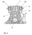
- FIG. 4 shows a further cross section through an internal combustion engine.
- FIG. 4 shows the web 7 extending between the cylinder tubes and the Bearing of the control shafts 4 in the crankcase 2.
- the cylinder block 1 is used for highly stressed to increase the stability Motors in gray cast iron with reduced wall thickness or in vermicular cast iron.
- the consequent exploitation of the higher strength of gray cast iron or Vermicular casting compared to aluminum can be advantageous in terms of lightweight construction be used to reduce weight. This can be done with a split version of cylinder block 1 and cylinder head these are still made of aluminum.
- a further weight-reducing measure consists in the actuating shafts 4 to train hollow.
- the support strips 6 can also be used for a targeted recording and forwarding Return oil from the cylinder head can be used. This is done via accordingly positioned bores 11 ( Figure 3) below the actuating shafts 4 a targeted introduction of return oil in the support bar volumes. By not shown separately The return oil can be channeled directly into the oil pan through channels in the storage chair levels become.
Landscapes
- Engineering & Computer Science (AREA)
- Chemical & Material Sciences (AREA)
- Combustion & Propulsion (AREA)
- Mechanical Engineering (AREA)
- General Engineering & Computer Science (AREA)
- Cylinder Crankcases Of Internal Combustion Engines (AREA)
Abstract
Description
Durch die hohe Anbindung der Stellwellen kann ebenfalls die notwendige Abdichtung (Dichtflansch, Dichtmanschette) zwischen Kurbelgehäuse und Zylinderblock oberhalb der Getriebeanbindung angeordnet werden, ohne daß durch die Dichtmanschette eine Motorverlängerung verursacht würde.
- Fig. 1:
- eine schematische Darstellung der erfindungsgemäßen Einrichtung zum Verlagern des Zylinderblocks und -kopfs gegenüber dem Kurbelgehäuse,
- Fig. 2:
- die erfindungsgemäße Einrichtung zum Verlagern des Zylinderblocks und -kopfs gegenüber dem Kurbelgehäuse als Getriebeschaltbild,
- Fig. 3:
- einen Schnitt durch den Zylinderblock mit Stellwellen und das Kurbelgehäuse,
- Fig. 4:
- einen weiteren Schnitt durch den Zylinderblock mit Stellwellen und das Kurbelgehäuse.
- 1
- Zylinderblock
- 2
- Kurbelgehäuse
- 3
- Lagergasse Kurbelwelle
- 4
- Stellwelle
- 5
- Verbindungsgerade
- 6
- Tragleisten
- 7
- Steg
- 8
- Exzenter
- 9
- Zylinderachse
- 10
- Lagergasse Stellwelle
- 11
- Bohrungen
Claims (8)
- Einrichtung zum Verlagern des Zylinderblocks und -kopfs gegenüber dem Kurbelgehäuse mit folgender Bauart,
das die Kurbelwelle aufnehmende Kurbelgehäuse weist in seinem Oberteil zwei beiderseits der Zylinder gelagerte Stellwellen mit Exzentern auf, die über die Länge des Kurbelgehäuses wechselweise verteilt angeordnet sind und in Aufnahmebohrungen von Lagerstegen oder - armen des Zylinderblocks eingreifen, gekennzeichnet durch folgende Merkmale:die Verbindungsgerade (5) der Lageraugen oder - arme des Zylinderblocks (1) steht etwa senkrecht zur Zylinderachse (9),die Lagerungen der Stellwellen (4) und deren Exzenter (8) verlaufen im oberen, dem Zylinderkopf nahen Bereich des Zylinderblocks (1),die Lagergassen (10) der Stellwellen (4) sind im Kurbelgehäuse (2) oberhalb von hohlträgerartig ausgebildeten Tragleisten (6), die sich über die Länge des Kurbelgehäuses (2) erstrecken, angeordnet. - Einrichtung nach Anspruch 1,
dadurch gekennzeichnet, dass das Kurbelgehäuse (2) aus Leichtmetall besteht und die Partie der Lagergasse der Kurbelwelle (3) und/oder die Partie der Lagergasse (10) der Stellwellen (4) als Grauguss-Eingussteil gestaltet ist. - Einrichtung nach Anspruch 1,
dadurch gekennzeichnet, dass die Lagergassen (10) der Stellwellen (4) im Kurbelgehäuse (2) aus Leichtmetall bestehen. - Einrichtung nach Anspruch 1 bis 3,
dadurch gekennzeichnet, dass die Stellwellen (4) einstückig oder gebaut ausgeführt sind. - Einrichtung nach Anspruch 1 bis 4,
dadurch gekennzeichnet, dass das Kurbelwellengehäuse (2) in Kurbelwellenebene geteilt ausgeführt ist, wobei das die Kurbelwelle aufnehmende Unterteil als Lagerbrücken- bzw. bedplate-Konstruktion ausgebildet ist. - Einrichtung nach Anspruch 1 bis 5,
dadurch gekennzeichnet, dass der Zylinderblock (1) aus wanddickenreduziertem Grauguss oder Vermikularguss besteht. - Einrichtung nach Anspruch 1 bis 6,
dadurch gekennzeichnet, dass die Stellwellen (4) hohl ausgebildet sind. - Einrichtung nach Anspruch 1 bis 7,
dadurch gekennzeichnet, dass die Tragleisten (6) zur Aufnahme von Rücklauföl über Bohrungen (11) mit dem Zylinderkopf und über in den Lagerstuhlebenen angeordneten Kanälen mit einer am Kurbelgehäuse angeordneten Ölwanne verbunden sind.
Applications Claiming Priority (2)
| Application Number | Priority Date | Filing Date | Title |
|---|---|---|---|
| DE10221334A DE10221334A1 (de) | 2002-05-10 | 2002-05-10 | Einrichtung zum Verlagern des Zylinderblocks und -kopfs gegenüber dem Kurbelgehäuse |
| DE10221334 | 2002-05-10 |
Publications (3)
| Publication Number | Publication Date |
|---|---|
| EP1361356A2 true EP1361356A2 (de) | 2003-11-12 |
| EP1361356A3 EP1361356A3 (de) | 2003-11-26 |
| EP1361356B1 EP1361356B1 (de) | 2006-01-11 |
Family
ID=29225161
Family Applications (1)
| Application Number | Title | Priority Date | Filing Date |
|---|---|---|---|
| EP03010316A Expired - Lifetime EP1361356B1 (de) | 2002-05-10 | 2003-05-07 | Einrichtung zum Verlagern des Zylinderblocks und -kopfs gegenüber dem Kurbelgehäuse |
Country Status (3)
| Country | Link |
|---|---|
| US (1) | US6880499B2 (de) |
| EP (1) | EP1361356B1 (de) |
| DE (2) | DE10221334A1 (de) |
Cited By (1)
| Publication number | Priority date | Publication date | Assignee | Title |
|---|---|---|---|---|
| DE102012217327A1 (de) | 2012-09-25 | 2014-06-12 | Markus Eberwein | Brennkraftmaschine mit variabler Verdichtung |
Families Citing this family (15)
| Publication number | Priority date | Publication date | Assignee | Title |
|---|---|---|---|---|
| DE102005020270A1 (de) * | 2005-04-30 | 2006-11-09 | Daimlerchrysler Ag | Brennkraftmaschine mit variablem Verdichtungsverhältnis |
| DE102005047203A1 (de) | 2005-10-01 | 2007-04-19 | Daimlerchrysler Ag | Brennkraftmaschine mit variablem Verdichtungsverhältnis |
| JP4281772B2 (ja) * | 2006-09-06 | 2009-06-17 | トヨタ自動車株式会社 | 可変圧縮比内燃機関 |
| DE102007010087A1 (de) * | 2007-03-02 | 2008-09-04 | Bernhard Meyer | Verbrennungsmotor mit veränderbaren Verdichtungsraum |
| DE102007053515A1 (de) | 2007-11-09 | 2009-05-14 | Bayerische Motoren Werke Aktiengesellschaft | Vorrichtung für eine Brennkraftmaschine zum Verlagern eines Zylinderkopfs mit Zylinderrohren gegenüber einem Kurbelgehäuse |
| DE102007053717B4 (de) * | 2007-11-10 | 2015-01-08 | Deutz Ag | Flachriementrieb einer Brennkraftmaschine |
| US8166929B2 (en) * | 2009-03-16 | 2012-05-01 | Manousos Pattakos | Variable compression ratio engine |
| DE102009048716A1 (de) * | 2009-10-08 | 2011-04-14 | Daimler Ag | Brennkraftmaschine |
| DE102012001648B4 (de) * | 2012-01-27 | 2014-04-30 | Audi Ag | Mehrgelenkskurbeltrieb einer Brennkraftmaschine sowie Verfahren zur Montage eines Mehrgelenkskurbeltriebs |
| KR20140119069A (ko) | 2012-02-09 | 2014-10-08 | 에드워드 찰스 멘들러 | 가변 압축비 엔진 |
| WO2014085425A2 (en) | 2012-11-28 | 2014-06-05 | Quinton Aaron | Cast dual wall bulkhead with integral oil drain |
| DE102014006471B4 (de) | 2014-04-29 | 2016-05-25 | Iav Gmbh Ingenieurgesellschaft Auto Und Verkehr | Verfahren zum Betrieb einer Brennkraftmaschine |
| DE102015005576B4 (de) | 2015-05-04 | 2022-10-13 | Iav Gmbh Ingenieurgesellschaft Auto Und Verkehr | Brennkraftmaschine mit variablem Verdichtungsverhältnis |
| WO2016195756A1 (en) * | 2015-06-01 | 2016-12-08 | Edward Charles Mendler | Variable compression ratio engine |
| DE102015111441B4 (de) | 2015-07-15 | 2021-03-04 | Iav Gmbh Ingenieurgesellschaft Auto Und Verkehr | Verstelleinrichtung für eine Brennkraftmaschine mit variablem Verdichtungsverhältnis |
Citations (1)
| Publication number | Priority date | Publication date | Assignee | Title |
|---|---|---|---|---|
| EP0426540A1 (de) | 1989-10-31 | 1991-05-08 | Bernard Condamin | Brennkraftmaschine mit variablem Hub |
Family Cites Families (2)
| Publication number | Priority date | Publication date | Assignee | Title |
|---|---|---|---|---|
| GB286723A (en) * | 1927-03-10 | 1928-07-05 | Francisco Rodero Carrasco | An internal combustion engine |
| SE501331C2 (sv) * | 1993-05-28 | 1995-01-16 | Saab Automobile | Strukturinneslutning av förbränningsmotor i syfte att reducera motorljud |
-
2002
- 2002-05-10 DE DE10221334A patent/DE10221334A1/de not_active Withdrawn
-
2003
- 2003-05-07 DE DE50302153T patent/DE50302153D1/de not_active Expired - Lifetime
- 2003-05-07 EP EP03010316A patent/EP1361356B1/de not_active Expired - Lifetime
- 2003-05-12 US US10/436,308 patent/US6880499B2/en not_active Expired - Fee Related
Patent Citations (1)
| Publication number | Priority date | Publication date | Assignee | Title |
|---|---|---|---|---|
| EP0426540A1 (de) | 1989-10-31 | 1991-05-08 | Bernard Condamin | Brennkraftmaschine mit variablem Hub |
Cited By (1)
| Publication number | Priority date | Publication date | Assignee | Title |
|---|---|---|---|---|
| DE102012217327A1 (de) | 2012-09-25 | 2014-06-12 | Markus Eberwein | Brennkraftmaschine mit variabler Verdichtung |
Also Published As
| Publication number | Publication date |
|---|---|
| EP1361356A3 (de) | 2003-11-26 |
| US6880499B2 (en) | 2005-04-19 |
| DE50302153D1 (de) | 2006-04-06 |
| DE10221334A1 (de) | 2003-11-20 |
| US20040035376A1 (en) | 2004-02-26 |
| EP1361356B1 (de) | 2006-01-11 |
Similar Documents
| Publication | Publication Date | Title |
|---|---|---|
| DE69107858T2 (de) | Brennkraftmaschine mit veränderbarem verdichtungsverhältnis und mit versteifer des kurbelgehäuses in der nähe der kurbelwellenlager. | |
| EP1361356B1 (de) | Einrichtung zum Verlagern des Zylinderblocks und -kopfs gegenüber dem Kurbelgehäuse | |
| DE69408456T2 (de) | Verbrennungsmotorgehäuse für motorlärmdämpfung | |
| DE3010635C2 (de) | ||
| DE102005029481B4 (de) | Pumpengetriebe | |
| EP0809749B1 (de) | Hubkolbenmaschine mit in kurbelwellenrichtung in einem maschinengehäuse benachbarten zylindern | |
| DE60019772T2 (de) | Brennkraftmaschine mit variablem Verdichtungsverhältnis und einstellbarer Ventailsteuerung | |
| WO1988008922A1 (fr) | Machine motrice ou de travail, notamment machine a combustion interne | |
| DD256894A5 (de) | Kolben-verbrennungsmotoren | |
| DE10142153B4 (de) | Motorrad | |
| DE3202421C2 (de) | ||
| WO2011085755A1 (de) | Reihen-brennkraftmaschine mit mehrgelenkskurbeltrieb sowie einer einzigen ausgleichswelle zur tilgung von massenkräften zweiter ordnung | |
| DE10055753A1 (de) | Hydrostatische Axialkolbenmaschine in Schrägscheibenbauweise | |
| EP0944784B1 (de) | Stützstruktur für das kurbelgehäuse einer hubkolben-brennkraftmaschine | |
| DE102010027351B4 (de) | Brennkraftmaschine mit verlängertem Expansionshub und Momentenausgleich | |
| DE69401168T2 (de) | Trägervorrichtung für eine Zylinderbuchse | |
| DE69936522T3 (de) | Steifer kurbelwellenhalter und betätigungsvorrichtung | |
| DE10084351B4 (de) | Anordnung zum Verhindern von mit Lagern zusammenhängenden Geräuschen bei Verbrennungsmotoren | |
| DE19745761A1 (de) | Variable Ventilsteuerung für Hubkolben-Brennkraftmaschinen | |
| DE19503443C1 (de) | Zweitakt-Gegenkolbenmotor | |
| DE69319154T2 (de) | Hubkolbenmotor mit kreuzkopf | |
| EP0044313A1 (de) | Kolbenmaschine. | |
| DE3119362A1 (de) | "vierzylinder-brennkraftmaschine mit einem massenausgleich zweiter ordnung" | |
| EP1674703B1 (de) | Kurbelwellenlagerbrücke für eine Brennkraftmaschine | |
| DE19846909B4 (de) | Kolbenmotor mit dem Mechanismus der Kolbenstabilisierung |
Legal Events
| Date | Code | Title | Description |
|---|---|---|---|
| PUAI | Public reference made under article 153(3) epc to a published international application that has entered the european phase |
Free format text: ORIGINAL CODE: 0009012 |
|
| PUAL | Search report despatched |
Free format text: ORIGINAL CODE: 0009013 |
|
| AK | Designated contracting states |
Kind code of ref document: A2 Designated state(s): AT BE BG CH CY CZ DE DK EE ES FI FR GB GR HU IE IT LI LU MC NL PT RO SE SI SK TR |
|
| AX | Request for extension of the european patent |
Extension state: AL LT LV MK |
|
| AK | Designated contracting states |
Kind code of ref document: A3 Designated state(s): AT BE BG CH CY CZ DE DK EE ES FI FR GB GR HU IE IT LI LU MC NL PT RO SE SI SK TR |
|
| AX | Request for extension of the european patent |
Extension state: AL LT LV MK |
|
| RIC1 | Information provided on ipc code assigned before grant |
Ipc: 7F 02F 7/00 A Ipc: 7F 02B 75/04 B |
|
| 17P | Request for examination filed |
Effective date: 20040216 |
|
| AKX | Designation fees paid |
Designated state(s): DE FR GB IT SE |
|
| GRAP | Despatch of communication of intention to grant a patent |
Free format text: ORIGINAL CODE: EPIDOSNIGR1 |
|
| GRAS | Grant fee paid |
Free format text: ORIGINAL CODE: EPIDOSNIGR3 |
|
| GRAA | (expected) grant |
Free format text: ORIGINAL CODE: 0009210 |
|
| AK | Designated contracting states |
Kind code of ref document: B1 Designated state(s): DE FR GB IT SE |
|
| GBT | Gb: translation of ep patent filed (gb section 77(6)(a)/1977) |
Effective date: 20060131 |
|
| REF | Corresponds to: |
Ref document number: 50302153 Country of ref document: DE Date of ref document: 20060406 Kind code of ref document: P |
|
| REG | Reference to a national code |
Ref country code: SE Ref legal event code: TRGR |
|
| ET | Fr: translation filed | ||
| PLBE | No opposition filed within time limit |
Free format text: ORIGINAL CODE: 0009261 |
|
| STAA | Information on the status of an ep patent application or granted ep patent |
Free format text: STATUS: NO OPPOSITION FILED WITHIN TIME LIMIT |
|
| 26N | No opposition filed |
Effective date: 20061012 |
|
| PGFP | Annual fee paid to national office [announced via postgrant information from national office to epo] |
Ref country code: FR Payment date: 20080228 Year of fee payment: 6 |
|
| PGFP | Annual fee paid to national office [announced via postgrant information from national office to epo] |
Ref country code: IT Payment date: 20080527 Year of fee payment: 6 |
|
| PGFP | Annual fee paid to national office [announced via postgrant information from national office to epo] |
Ref country code: GB Payment date: 20080506 Year of fee payment: 6 |
|
| PGFP | Annual fee paid to national office [announced via postgrant information from national office to epo] |
Ref country code: SE Payment date: 20090525 Year of fee payment: 7 |
|
| GBPC | Gb: european patent ceased through non-payment of renewal fee |
Effective date: 20090507 |
|
| REG | Reference to a national code |
Ref country code: FR Ref legal event code: ST Effective date: 20100129 |
|
| PG25 | Lapsed in a contracting state [announced via postgrant information from national office to epo] |
Ref country code: FR Free format text: LAPSE BECAUSE OF NON-PAYMENT OF DUE FEES Effective date: 20090602 |
|
| PG25 | Lapsed in a contracting state [announced via postgrant information from national office to epo] |
Ref country code: GB Free format text: LAPSE BECAUSE OF NON-PAYMENT OF DUE FEES Effective date: 20090507 |
|
| EUG | Se: european patent has lapsed | ||
| PG25 | Lapsed in a contracting state [announced via postgrant information from national office to epo] |
Ref country code: IT Free format text: LAPSE BECAUSE OF NON-PAYMENT OF DUE FEES Effective date: 20090507 Ref country code: SE Free format text: LAPSE BECAUSE OF NON-PAYMENT OF DUE FEES Effective date: 20100508 |
|
| PGFP | Annual fee paid to national office [announced via postgrant information from national office to epo] |
Ref country code: DE Payment date: 20150626 Year of fee payment: 13 |
|
| REG | Reference to a national code |
Ref country code: DE Ref legal event code: R119 Ref document number: 50302153 Country of ref document: DE |
|
| PG25 | Lapsed in a contracting state [announced via postgrant information from national office to epo] |
Ref country code: DE Free format text: LAPSE BECAUSE OF NON-PAYMENT OF DUE FEES Effective date: 20161201 |