EP1359378A1 - Vorrichtung für eine lösbare Befestigung von dickwandigen Mehrschicht-Glasplatten, insbesondere elektrischen Glasheizkörpern - Google Patents
Vorrichtung für eine lösbare Befestigung von dickwandigen Mehrschicht-Glasplatten, insbesondere elektrischen Glasheizkörpern Download PDFInfo
- Publication number
- EP1359378A1 EP1359378A1 EP03008318A EP03008318A EP1359378A1 EP 1359378 A1 EP1359378 A1 EP 1359378A1 EP 03008318 A EP03008318 A EP 03008318A EP 03008318 A EP03008318 A EP 03008318A EP 1359378 A1 EP1359378 A1 EP 1359378A1
- Authority
- EP
- European Patent Office
- Prior art keywords
- parts
- plate
- glass plate
- hanging
- glass
- Prior art date
- Legal status (The legal status is an assumption and is not a legal conclusion. Google has not performed a legal analysis and makes no representation as to the accuracy of the status listed.)
- Granted
Links
Images



Classifications
-
- F—MECHANICAL ENGINEERING; LIGHTING; HEATING; WEAPONS; BLASTING
- F24—HEATING; RANGES; VENTILATING
- F24H—FLUID HEATERS, e.g. WATER OR AIR HEATERS, HAVING HEAT-GENERATING MEANS, e.g. HEAT PUMPS, IN GENERAL
- F24H9/00—Details
- F24H9/06—Arrangement of mountings or supports
-
- F—MECHANICAL ENGINEERING; LIGHTING; HEATING; WEAPONS; BLASTING
- F24—HEATING; RANGES; VENTILATING
- F24D—DOMESTIC- OR SPACE-HEATING SYSTEMS, e.g. CENTRAL HEATING SYSTEMS; DOMESTIC HOT-WATER SUPPLY SYSTEMS; ELEMENTS OR COMPONENTS THEREFOR
- F24D13/00—Electric heating systems
- F24D13/02—Electric heating systems solely using resistance heating, e.g. underfloor heating
- F24D13/022—Electric heating systems solely using resistance heating, e.g. underfloor heating resistances incorporated in construction elements
-
- Y—GENERAL TAGGING OF NEW TECHNOLOGICAL DEVELOPMENTS; GENERAL TAGGING OF CROSS-SECTIONAL TECHNOLOGIES SPANNING OVER SEVERAL SECTIONS OF THE IPC; TECHNICAL SUBJECTS COVERED BY FORMER USPC CROSS-REFERENCE ART COLLECTIONS [XRACs] AND DIGESTS
- Y02—TECHNOLOGIES OR APPLICATIONS FOR MITIGATION OR ADAPTATION AGAINST CLIMATE CHANGE
- Y02B—CLIMATE CHANGE MITIGATION TECHNOLOGIES RELATED TO BUILDINGS, e.g. HOUSING, HOUSE APPLIANCES OR RELATED END-USER APPLICATIONS
- Y02B30/00—Energy efficient heating, ventilation or air conditioning [HVAC]
Definitions
- the invention relates to a device for a releasable attachment of thick-walled multi-layer glass plates, especially disc-shaped electric glass radiators with power supply, on walls or Support frames.
- the flawless and secure mounting of the Panes of glass on walls and supporting structures, especially in Interior area, but also shown in the outside area, as in one vertical fastening of thick-walled multilayer glass panes and Glass plates, such as those used for disc-shaped electrical glass radiators with power feed, high demands on the Assembly security are provided.
- the fasteners are meant to but also be designed so that on the one hand a simple and safe Assembly, but also easy disassembly of the glass panes and glass plates is guaranteed without damage.
- the invention has for its object a device for a detachable Attachment of thick-walled multilayer glass plates, especially of disc-shaped electrical glass radiators with power supply
- a device for a detachable Attachment of thick-walled multilayer glass plates especially of disc-shaped electrical glass radiators with power supply
- a device characterized in that several holders are provided with the upright glass plate or the Radiators on the back in an upper and a lower area are screwed or firmly glued and from a wall fastening part and one of them detachable hanging part, which with the plate level parallel, horizontally aligned supports and perpendicular to them Aligned web parts so interlocking that the plate with the hanging parts attached to it in the wall mounting parts from can be hung up so far that the attached to the plate lower suspension parts first from supports to the lower Wall fasteners are supported, and that after a minor
- the plate can also be lifted and swiveled into a vertical position engage the upper suspension parts in the upper wall mounting parts in such a way that the plate by resting on both the lower and the upper Wall mounting parts is secured in the mounting position.
- the invention has the advantage that the two-part holder from one Wall mounting part and a detachable hanging part exist.
- the wall mounting parts on a Building wall or mounted on a suitable supporting structure while the hanging parts on the back of the thick-walled glass plates or Glass radiators are attached.
- the hanging parts are then from the Back of the glass plate or the glass radiator.
- This can then in a few simple steps with the lower hanging parts in the associated lower wall mounting parts attached at an angle from above, light raised, in a vertical position with respect to the top Wall mounting parts brought and then in the final Installation position on all holders are lowered.
- the slant In addition to easy assembly, the disc is mainly used to clean the Disc also on the back. To dismantle the above described steps in reverse order just as easy be carried out.
- each wall mounting member prefers one cylindrical base with a horizontal parallel to the plate plane aligned cross slot and one in the direction of the base axis vertical longitudinal slot for attaching the to the glass plate attached attachment part such that the glass plate or the Radiator for wall mounting with the wall mounting parts matching suspension parts from above into the longitudinal slot on the Wall mounting part can be hung, with each hanging part one engaging in the longitudinal slot on the wall fastening part with a precise fit has flat retaining web with transverse trunnion and in the Cross slot on the wall mounting part engages so deep that the trunnion lie at the bottom of the cross slot and the glass plate in the Secure mounting position.
- the Transverse slot on each lower wall mounting part a greater depth than that Has cross slot on each upper wall mounting part. This will make the Glass pane both when inserting and when removing from the Fastening devices in the lower area until final assembly intercepted or dismantled in an inclined position.
- the assembly and disassembly of the glass sheet or plate is also also further facilitated in that the retaining web of the hanging part on the lower
- the end of the holder is chamfered in a wedge shape and that of the end face of the Wall fastening part opposite end face of the hanging part in is spaced such that the glass plate or the radiator with the brackets attached to it in a first step in the transverse slots on the wall mounting parts raised vertically and after loosening from the upper wall mounting parts around the trunnion on the lower Hanging parts tilted forward and then out of the cross slots the lower wall mounting parts fully lifted out to the front can be.
- the device shown in the drawing is used for releasable attachment of thick-walled multilayer glass plates 1, in particular disc-shaped electric glass radiators with power supply, on walls or Support frames.
- Every holder consists of a wall mounting part 4a or 4b and a detachable part Hanging part 5a or 5b, the horizontal with the plate plane parallel aligned supports and perpendicular to these aligned web parts interlock with one another.
- the plate 1 with the attached Hanging parts 5a, 5b can be in the wall mounting parts 4a, 4b from above be attached so far that the lower attached to the plate 1 Hanging parts 5b first from supports 6 to the lower ones Wall mounting parts 4b are supported.
- Each hanging part 5a, 5b has one in the longitudinal slot 8 on the wall fastening part 4a, 4b precisely fitting flat retaining web 9a or 9b with transverse Support pin 10, 11 in the transverse slot 7a and 7b on the Wall mounting part 4a, 4b engages so deep that the both sides of the Retaining bars 9a and 9b protruding trunnions 10, 11 at the bottom of Cross slot 7a, 7b abut and the glass plate 1 in the mounting position secure (Fig. 1).
- the transverse slot 7b has at each lower Wall mounting part 4b a greater depth than the transverse slot 7a on each upper wall mounting part 4a.
- the hanging part 5a of the upper holder 2 on the end face 12a of the associated Wall mounting part 4a flat.
- the holding web 9b of the hanging part 5b on the lower holder 3 according to FIGS. 2, 3 and 6 at the end beveled in such a wedge shape at an angle 13 of approximately 15 to 20 ° and the the end face opposite the end face 12b of the wall fastening part 4b 14 of the hanging part 5b is arranged at such a distance 15 (FIG.
- the holders 2, 3 For attachment to the glass plate 1, the holders 2, 3 according to FIG. 1 to 7 one projecting coaxially forward from the hanging part 5a or 5b Mounting pin 20 on the through a bore 21 in the glass plate 1st protrudes through and on the outside thereof with an end cap 22 is screwed.
- the screw connection of the glass plate 1 or the radiator the holes 21 for the holder 2, 3 is also with double-sided silicone washers 23 provided.
- individual holders 2, 3 can also be used provided an electrical connection 24 and at the front end of the Hanging part 5a, 5b with the glass plate 1 or the radiator Adhesive attachment must be firmly connected.
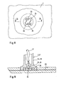
- Terminals 25, 26 for an electrical connection as a radiator trained glass plate 1 with a power supply cable 27 in one End-side recess 28 on the hanging part of the holder 2, 3 in question arranged sunk, making contact with an electrically conductive layer 29 of the glass radiator.
Landscapes
- Engineering & Computer Science (AREA)
- Physics & Mathematics (AREA)
- Thermal Sciences (AREA)
- Chemical & Material Sciences (AREA)
- Combustion & Propulsion (AREA)
- Mechanical Engineering (AREA)
- General Engineering & Computer Science (AREA)
- Load-Bearing And Curtain Walls (AREA)
- Joining Of Glass To Other Materials (AREA)
- Connection Of Plates (AREA)
- Domestic Hot-Water Supply Systems And Details Of Heating Systems (AREA)
- Cooling, Air Intake And Gas Exhaust, And Fuel Tank Arrangements In Propulsion Units (AREA)
Abstract
Description
- Fig. 1
- einen oberen und einen unteren Halter für eine dickwandige Mehrschicht-Glasplatte oder einen Glasheizkörper in perspektivischer Ansicht,
- Fig. 2
- eine auseinandergezogene Darstellung des unteren Halters von Fig. 1 ebenfalls in perspektivischer Ansicht.
- Fig. 3
- eine auseinandergezogene Seitenansicht des unteren Halters von Fig. 1 und 2,
- Fig. 4
- eine Seitenansicht eines oberen Halters mit Glasplatte,
- Fig. 5
- eine Draufsicht auf den Halter von Fig. 4
- Fig. 6
- eine Seitenansicht eines unteren Halters mit Glasplatte,
- Fig. 7
- eine Draufsicht auf den Halter von Fig. 6,
- Fig. 8
- eine schematische Vorderansicht eines oberen oder unteren Halters mit elektrischen Anschlußklemmen zur Stromzuführung, beispielsweise zu einem elektrischen Glasheizkörper, und
- Fig. 9
- einen Schnitt durch den Halter von Fig. 8 gemäß Schnittlinie IX-IX.
- 1
- Mehrschicht-Glasplatte, Glasheizkörper
- 2
- Halter
- 3
- Halter
- 4a
- Wandbefestigungsteil
- 4b
- Wandbefestigungsteil
- 5a
- Einhängeteil
- 5b
- Einhängeteil
- 6
- Auflager
- 7a
- Querschlitz
- 7b
- Querschlitz
- 8
- Längsschlitz
- 9a
- Haltesteg
- 9b
- Haltesteg
- 10
- Tragzapfen
- 11
- Tragzapfen
- 12a
- Stirnfläche
- 12b
- Stirnfläche
- 13
- Winkel
- 14
- Stirnseite
- 15
- Abstand
- 20
- Montagezapfen
- 21
- Bohrung
- 22
- Abschlußkappe
- 23
- Silikon-Zwischenscheiben
- 24
- Elektroanschluß
- 25
- Anschlußklemme
- 26
- Anschlußklemme
- 27
- Strom-Zuführungskabel
- 28
- Vertiefung
- 29
- elektrisch leitende Schicht
- I
- Richtungspfeil
- II
- Richtungspfeil
- III
- Richtungspfeil
- IV
- Richtungspfeil
Claims (9)
- Vorrichtung für eine lösbare Befestigung von dickwandigen Mehrschicht-Glasplatten, insbesondere von scheibenförmigen elektrischen Glasheizkörpern mit Stromeinspeisung, an Wänden oder Traggestellen, dadurch gekennzeichnet, daß mehrere Halter (2, 3) vorgesehen sind, die mit der aufrecht stehenden Glasplatte (1) oder dem Heizkörper an der Rückseite in einem oberen und in einem unteren Bereich verschraubt oder fest verklebt sind und aus einem Wandbefestigungsteil (4a, 4b) und einem davon lösbaren Einhängeteil (5a, 5b) bestehen, die mit zur Plattenebene parallelen, horizontal ausgerichteten Auflagern (6) und senkrecht zu diesen ausgerichteten Stegteilen derart gabelförmig ineinandergreifen, daß die Platte (1) mit den daran befestigten Einhängeteilen (5a, 5b) in die Wandbefestigungsteile (4a, 4b) von oben her so weit eingehängt werden kann, daß die an der Platte (1) befestigten unteren Einhängeteile (5b) zuerst von Auflagern an den unteren Wandbefestigungsteilen (4b) abgestützt werden, und daß nach einem geringfügigen Anheben und Verschwenken der Platte (1) in eine senkrechte Lage auch die oberen Einhängeteile (5a) in die oberen Wandbefestigungsteile (4a) derart einrasten, daß die Platte (1) durch Auflage sowohl an den unteren als auch an den oberen Wandbefestigungsteilen (4a, 4b) in der Montagestellung gesichert ist.
- Vorrichtung nach Anspruch 1, dadurch gekennzeichnet, daß jedes Wandbefestigungsteil (4a, 4b) einen vorzugsweise zylindrischen Sockel mit einem parallel zur Plattenebene horizontal ausgerichteten Querschlitz (7a, 7b) sowie einem in Richtung der Sockelachse verlaufenden senkrechten Längsschlitz (8) zum Befestigen des an der Glasplatte (1) befestigten Einhängeteils (5a, 5b) derart aufweist, daß die Glasplatte (1) oder der Heizkörper bei der Wandmontage mit den zu den Wandbefestigungsteilen (4a, 4b) passenden Einhängeteilen (5a, 5b) von oben her in den Längsschlitz (8) an dem Wandbefestigungsteil (4a bzw. 4b) eingehängt werden kann, wobei jedes Einhängeteil (5a, 5b) einen in den Längsschlitz (8) an dem Wandbefestigungsteil (4a, 4b) paßgenau eingreifenden flachen Haltesteg (9a bzw. 9b) mit querverlaufenden Tragzapfen (10, 11) aufweist und in den Querschlitz (7a, 7b) an dem Wandbefestigungsteil (4a, 4b) so tief eingreift, daß die Tragzapfen (10, 11) am Grunde des Querschlitzes (7a, 7b) anliegen und die Glasplatte (1) in der Montagestellung sichern.
- Vorrichtung nach Anspruch 1 oder 2, dadurch gekennzeichnet,daß der Querschlitz (7b) an jedem unteren Wandbefestigungsteil (4b) eine größere Tiefe als der Querschlitz (7a) an jedem oberen Wandbefestigungsteil (4a) aufweist.
- Vorrichtung nach einem der Ansprüche 1 bis 3, dadurchgekennzeichnet, daß das Einhängeteil (5a) des oberen Halters (2) an der Stirnfläche (12a) des zugehörigen Wandbefestigungsteils (4a) flächig anliegt.
- Vorrichtung nach einem der Ansprüche 1 bis 4, dadurch gekennzeichnet, daß der Haltesteg (9b) des Einhängeteils (5b) an dem unteren Halter (3) endseitig derart keilförmig abgeschrägt und die der Stirnfläche (12b) des Wandbefestigungsteils (4b) gegenüberliegende Stirnseite (14) des Einhängeteils (5b) in einem solchen Abstand (15) angeordnet ist, daß die Glasplatte (1) oder der Heizkörper mit den daran befestigten Haltern (2, 3) in einem ersten Schritt in den Querschlitzen (7a, 7b) an den Wandbefestigungsteilen (4a, 4b) senkrecht angehoben und nach Lösen aus den oberen Wandbefestigungsteilen (4a) um die Tragzapfen (10, 11) an den unteren Einhängeteilen (5b) nach vorn gekippt und anschließend aus den Querschlitzen (7b) an den unteren Wandbefestigungsteilen (4b) vollständig nach vorne herausgehoben werden kann.
- Vorrichtung nach einem der Ansprüche 1 bis 5, dadurch gekennzeichnet, daß die Halter (2, 3) einen von dem Einhängeteil (5a, 5b) koaxial nach vorne hervorstehenden Montagezapfen (20) aufweisen, der durch eine Bohrung (21) in der Glasplatte (1) hindurchragt und an deren Außenseite mit einer Abschlußkappe (22) verschraubt ist.
- Vorrichtung nach Anspruch 6, dadurch gekennzeichnet, daß die Verschraubung der Glasplatte (1) oder des Heizkörpers an den Bohrungen (21) für die Halter (2, 3) mit beidseitigen Silikon-Zwischenscheiben (23) versehen ist.
- Vorrichtung nach einem der Ansprüche 1 bis 7, dadurch gekennzeichnet, daß einzelne Halter (2, 3) mit einem Elektroanschluß (24) versehen und an dem stirnseitigen Ende des Einhängeteiles (5a, 5b) mit der Glasplatte (1) oder dem Heizkörper mittels Klebebefestigung fest verbunden sind.
- Vorrichtung nach Anspruch 8, dadurch gekennzeichnet, daß Anschlußklemmen (25, 26) für eine elektrische Verbindung der als Heizkörper ausgebildeten Glasplatte (1) mit einem Strom-Zuführungskabel (27) in einer stirnseitigen Vertiefung (28) an dem Einhängeteil (5a bzw. 5b) des betreffenden Halters versenkt angeordnet sind und den Kontakt zu einer elektrisch leitenden Schicht (29) des Glas-Heizkörpers herstellen.
Applications Claiming Priority (2)
| Application Number | Priority Date | Filing Date | Title |
|---|---|---|---|
| DE20207105U DE20207105U1 (de) | 2002-05-04 | 2002-05-04 | Vorrichtung für eine lösbare Befestigung von dickwandigen Mehrschicht-Glasplatten, insbesondere elektrischen Glasheizkörpern |
| DE20207105U | 2002-05-04 |
Publications (2)
| Publication Number | Publication Date |
|---|---|
| EP1359378A1 true EP1359378A1 (de) | 2003-11-05 |
| EP1359378B1 EP1359378B1 (de) | 2006-05-31 |
Family
ID=7970843
Family Applications (1)
| Application Number | Title | Priority Date | Filing Date |
|---|---|---|---|
| EP03008318A Expired - Lifetime EP1359378B1 (de) | 2002-05-04 | 2003-04-10 | Vorrichtung für eine lösbare Befestigung von dickwandigen Mehrschicht-Glasplatten, insbesondere elektrischen Glasheizkörpern |
Country Status (4)
| Country | Link |
|---|---|
| EP (1) | EP1359378B1 (de) |
| AT (1) | ATE328248T1 (de) |
| DE (2) | DE20207105U1 (de) |
| ES (1) | ES2262918T3 (de) |
Cited By (1)
| Publication number | Priority date | Publication date | Assignee | Title |
|---|---|---|---|---|
| CN113917768A (zh) * | 2019-07-31 | 2022-01-11 | 宁波舜宇车载光学技术有限公司 | 光学装置及其应用 |
Families Citing this family (3)
| Publication number | Priority date | Publication date | Assignee | Title |
|---|---|---|---|---|
| FR2937121B1 (fr) * | 2008-10-13 | 2010-11-19 | Jean Michel Perrier | Radiateur et equipement de chauffage de batiment. |
| CN102888918B (zh) * | 2012-09-26 | 2015-08-19 | 苏州金螳螂幕墙有限公司 | 一种倒置式玻璃幕墙用的立柱挂件 |
| CN110145063B (zh) * | 2019-06-10 | 2020-06-30 | 山东雄狮建筑装饰股份有限公司 | 一种双层玻璃幕墙 |
Citations (4)
| Publication number | Priority date | Publication date | Assignee | Title |
|---|---|---|---|---|
| DE4008500A1 (de) * | 1989-03-17 | 1990-09-20 | Kyodo Denki | Vorrichtung zum anzeigen des vollstaendigen und des unvollstaendigen anzugs von schraubenteilen |
| DE19809617A1 (de) * | 1998-03-06 | 1999-10-14 | Brueder Eckelt & Co Glastech | Befestigungseinrichtung für Platten, insbesondere für Glasplatten |
| EP0994308A1 (de) * | 1998-10-14 | 2000-04-19 | G.C. Technology | Spritzgegossene Heizungsplatte, Zusammensetzung, Vorrichtung und Verfahren zu Herstellung |
| DE10016399A1 (de) * | 1999-09-30 | 2001-04-12 | Inglas Innovative Glassysteme | Vorrichtung zur Halterung von Glasscheiben |
Family Cites Families (2)
| Publication number | Priority date | Publication date | Assignee | Title |
|---|---|---|---|---|
| DE9311681U1 (de) | 1993-08-05 | 1993-10-14 | Kermi Gmbh, 94447 Plattling | An einer Wand befestigbare Vorrichtung zur Halterung von Heizkörpern |
| DE19844324C2 (de) | 1998-09-28 | 2003-09-25 | Atj Systembauteile Gmbh | Plattenhaltersystem |
-
2002
- 2002-05-04 DE DE20207105U patent/DE20207105U1/de not_active Expired - Lifetime
-
2003
- 2003-04-10 AT AT03008318T patent/ATE328248T1/de not_active IP Right Cessation
- 2003-04-10 EP EP03008318A patent/EP1359378B1/de not_active Expired - Lifetime
- 2003-04-10 ES ES03008318T patent/ES2262918T3/es not_active Expired - Lifetime
- 2003-04-10 DE DE50303543T patent/DE50303543D1/de not_active Expired - Fee Related
Patent Citations (4)
| Publication number | Priority date | Publication date | Assignee | Title |
|---|---|---|---|---|
| DE4008500A1 (de) * | 1989-03-17 | 1990-09-20 | Kyodo Denki | Vorrichtung zum anzeigen des vollstaendigen und des unvollstaendigen anzugs von schraubenteilen |
| DE19809617A1 (de) * | 1998-03-06 | 1999-10-14 | Brueder Eckelt & Co Glastech | Befestigungseinrichtung für Platten, insbesondere für Glasplatten |
| EP0994308A1 (de) * | 1998-10-14 | 2000-04-19 | G.C. Technology | Spritzgegossene Heizungsplatte, Zusammensetzung, Vorrichtung und Verfahren zu Herstellung |
| DE10016399A1 (de) * | 1999-09-30 | 2001-04-12 | Inglas Innovative Glassysteme | Vorrichtung zur Halterung von Glasscheiben |
Cited By (1)
| Publication number | Priority date | Publication date | Assignee | Title |
|---|---|---|---|---|
| CN113917768A (zh) * | 2019-07-31 | 2022-01-11 | 宁波舜宇车载光学技术有限公司 | 光学装置及其应用 |
Also Published As
| Publication number | Publication date |
|---|---|
| ATE328248T1 (de) | 2006-06-15 |
| DE20207105U1 (de) | 2002-09-12 |
| EP1359378B1 (de) | 2006-05-31 |
| DE50303543D1 (de) | 2006-07-06 |
| ES2262918T3 (es) | 2006-12-01 |
Similar Documents
| Publication | Publication Date | Title |
|---|---|---|
| EP1064707B1 (de) | Rahmengestell für einen schaltschrank | |
| DE69803731T2 (de) | Verfahren und vorrichtung zum einbau eines aufzugs | |
| DE3714196C2 (de) | Versorgungsbalken für die Intensivpflege | |
| EP1359378A1 (de) | Vorrichtung für eine lösbare Befestigung von dickwandigen Mehrschicht-Glasplatten, insbesondere elektrischen Glasheizkörpern | |
| DE3143518C2 (de) | Halter für Stromsammelschienen | |
| EP0262090A1 (de) | Befestigungselement zur Befestigung von Einsätzen an Seitenwänden einer Möbelstruktur | |
| EP0024467A2 (de) | Vorrichtung zum Halten von Paneelen beim Befestigen an einer Tragkonstruktion | |
| EP1182306A2 (de) | Befestigungssystem für Wandelemente an Gebäudewänden | |
| DE202023101963U1 (de) | Montageset zum Aufbau einer Ladesäule einer Elektro-Ladestation | |
| DE69119167T2 (de) | Verfahren für die Installierung von die Schachttüren eines Aufzugs | |
| DE102018002439A1 (de) | Modulares Tragprofil | |
| DE29502143U1 (de) | Höhenverstellbare Stützvorrichtung für Raummodule | |
| EP0301119B1 (de) | Steckbaugruppe | |
| EP0503527B1 (de) | Anschluss von Telekommunikationsgeräten | |
| DE19808759C2 (de) | Montagewerkzeug für Glasabschnitte | |
| CH670847A5 (de) | ||
| DE10124000B4 (de) | Decke eines Raumes in Bauwerken | |
| EP0593871B1 (de) | Leuchtenanordnung mit hinter- und/oder nebeneinander angeordneten Leuchtenkörpern | |
| EP0331796A1 (de) | Verstärkte Aufhängevorrichtung für Kabel | |
| DE69903006T2 (de) | Rollengeführter tisch für unterkreissäge | |
| DE29720336U1 (de) | Halter zur Verbindung von Platten, insbesondere von Glasplatten | |
| EP0627562A1 (de) | Klemmelement zur Befestigung flacher Körper über einer Unterlage | |
| DE202023104514U1 (de) | Universal-Gerätehalter zur Befestigung an Bahnschienen | |
| WO2017182056A1 (de) | Gegenhalter für pv-modulklemmen bei freiflächenanlagen | |
| EP0768497A1 (de) | Standkonsole für Heizkörper |
Legal Events
| Date | Code | Title | Description |
|---|---|---|---|
| PUAI | Public reference made under article 153(3) epc to a published international application that has entered the european phase |
Free format text: ORIGINAL CODE: 0009012 |
|
| AK | Designated contracting states |
Kind code of ref document: A1 Designated state(s): AT BE BG CH CY CZ DE DK EE ES FI FR GB GR HU IE IT LI LU MC NL PT SE SI SK TR |
|
| AX | Request for extension of the european patent |
Extension state: AL LT LV MK RO |
|
| 17P | Request for examination filed |
Effective date: 20040312 |
|
| AKX | Designation fees paid |
Designated state(s): AT BE BG CH CY CZ DE DK EE ES FI FR GB GR HU IE IT LI LU MC NL PT SE SI SK TR |
|
| 17Q | First examination report despatched |
Effective date: 20050201 |
|
| GRAP | Despatch of communication of intention to grant a patent |
Free format text: ORIGINAL CODE: EPIDOSNIGR1 |
|
| GRAS | Grant fee paid |
Free format text: ORIGINAL CODE: EPIDOSNIGR3 |
|
| GRAA | (expected) grant |
Free format text: ORIGINAL CODE: 0009210 |
|
| AK | Designated contracting states |
Kind code of ref document: B1 Designated state(s): AT BE BG CH CY CZ DE DK EE ES FI FR GB GR HU IE IT LI LU MC NL PT SE SI SK TR |
|
| PG25 | Lapsed in a contracting state [announced via postgrant information from national office to epo] |
Ref country code: SI Free format text: LAPSE BECAUSE OF FAILURE TO SUBMIT A TRANSLATION OF THE DESCRIPTION OR TO PAY THE FEE WITHIN THE PRESCRIBED TIME-LIMIT Effective date: 20060531 Ref country code: IE Free format text: LAPSE BECAUSE OF FAILURE TO SUBMIT A TRANSLATION OF THE DESCRIPTION OR TO PAY THE FEE WITHIN THE PRESCRIBED TIME-LIMIT Effective date: 20060531 Ref country code: IT Free format text: LAPSE BECAUSE OF FAILURE TO SUBMIT A TRANSLATION OF THE DESCRIPTION OR TO PAY THE FEE WITHIN THE PRESCRIBED TIME-LIMIT;WARNING: LAPSES OF ITALIAN PATENTS WITH EFFECTIVE DATE BEFORE 2007 MAY HAVE OCCURRED AT ANY TIME BEFORE 2007. THE CORRECT EFFECTIVE DATE MAY BE DIFFERENT FROM THE ONE RECORDED. Effective date: 20060531 Ref country code: CZ Free format text: LAPSE BECAUSE OF FAILURE TO SUBMIT A TRANSLATION OF THE DESCRIPTION OR TO PAY THE FEE WITHIN THE PRESCRIBED TIME-LIMIT Effective date: 20060531 Ref country code: FI Free format text: LAPSE BECAUSE OF FAILURE TO SUBMIT A TRANSLATION OF THE DESCRIPTION OR TO PAY THE FEE WITHIN THE PRESCRIBED TIME-LIMIT Effective date: 20060531 Ref country code: SK Free format text: LAPSE BECAUSE OF FAILURE TO SUBMIT A TRANSLATION OF THE DESCRIPTION OR TO PAY THE FEE WITHIN THE PRESCRIBED TIME-LIMIT Effective date: 20060531 |
|
| REG | Reference to a national code |
Ref country code: CH Ref legal event code: EP Ref country code: GB Ref legal event code: FG4D Free format text: NOT ENGLISH |
|
| REG | Reference to a national code |
Ref country code: IE Ref legal event code: FG4D Free format text: LANGUAGE OF EP DOCUMENT: GERMAN |
|
| REF | Corresponds to: |
Ref document number: 50303543 Country of ref document: DE Date of ref document: 20060706 Kind code of ref document: P |
|
| REG | Reference to a national code |
Ref country code: CH Ref legal event code: NV Representative=s name: KATZAROV S.A. |
|
| GBT | Gb: translation of ep patent filed (gb section 77(6)(a)/1977) |
Effective date: 20060808 |
|
| PG25 | Lapsed in a contracting state [announced via postgrant information from national office to epo] |
Ref country code: DK Free format text: LAPSE BECAUSE OF FAILURE TO SUBMIT A TRANSLATION OF THE DESCRIPTION OR TO PAY THE FEE WITHIN THE PRESCRIBED TIME-LIMIT Effective date: 20060831 Ref country code: SE Free format text: LAPSE BECAUSE OF FAILURE TO SUBMIT A TRANSLATION OF THE DESCRIPTION OR TO PAY THE FEE WITHIN THE PRESCRIBED TIME-LIMIT Effective date: 20060831 |
|
| PG25 | Lapsed in a contracting state [announced via postgrant information from national office to epo] |
Ref country code: PT Free format text: LAPSE BECAUSE OF FAILURE TO SUBMIT A TRANSLATION OF THE DESCRIPTION OR TO PAY THE FEE WITHIN THE PRESCRIBED TIME-LIMIT Effective date: 20061031 |
|
| ET | Fr: translation filed | ||
| REG | Reference to a national code |
Ref country code: ES Ref legal event code: FG2A Ref document number: 2262918 Country of ref document: ES Kind code of ref document: T3 |
|
| REG | Reference to a national code |
Ref country code: IE Ref legal event code: FD4D |
|
| PLBE | No opposition filed within time limit |
Free format text: ORIGINAL CODE: 0009261 |
|
| STAA | Information on the status of an ep patent application or granted ep patent |
Free format text: STATUS: NO OPPOSITION FILED WITHIN TIME LIMIT |
|
| 26N | No opposition filed |
Effective date: 20070301 |
|
| PGFP | Annual fee paid to national office [announced via postgrant information from national office to epo] |
Ref country code: CH Payment date: 20070706 Year of fee payment: 5 |
|
| GBPC | Gb: european patent ceased through non-payment of renewal fee |
Effective date: 20070410 |
|
| BERE | Be: lapsed |
Owner name: G.- FUR GLASBAUBESCHLAGE M.B.H. *SWS Effective date: 20070430 |
|
| NLV4 | Nl: lapsed or anulled due to non-payment of the annual fee |
Effective date: 20071101 |
|
| PG25 | Lapsed in a contracting state [announced via postgrant information from national office to epo] |
Ref country code: NL Free format text: LAPSE BECAUSE OF NON-PAYMENT OF DUE FEES Effective date: 20071101 Ref country code: DE Free format text: LAPSE BECAUSE OF NON-PAYMENT OF DUE FEES Effective date: 20071101 |
|
| PG25 | Lapsed in a contracting state [announced via postgrant information from national office to epo] |
Ref country code: BE Free format text: LAPSE BECAUSE OF NON-PAYMENT OF DUE FEES Effective date: 20070430 |
|
| PG25 | Lapsed in a contracting state [announced via postgrant information from national office to epo] |
Ref country code: GB Free format text: LAPSE BECAUSE OF NON-PAYMENT OF DUE FEES Effective date: 20070410 Ref country code: GR Free format text: LAPSE BECAUSE OF FAILURE TO SUBMIT A TRANSLATION OF THE DESCRIPTION OR TO PAY THE FEE WITHIN THE PRESCRIBED TIME-LIMIT Effective date: 20060901 |
|
| PG25 | Lapsed in a contracting state [announced via postgrant information from national office to epo] |
Ref country code: BG Free format text: LAPSE BECAUSE OF FAILURE TO SUBMIT A TRANSLATION OF THE DESCRIPTION OR TO PAY THE FEE WITHIN THE PRESCRIBED TIME-LIMIT Effective date: 20060831 |
|
| REG | Reference to a national code |
Ref country code: ES Ref legal event code: FD2A Effective date: 20070411 |
|
| PG25 | Lapsed in a contracting state [announced via postgrant information from national office to epo] |
Ref country code: FR Free format text: LAPSE BECAUSE OF NON-PAYMENT OF DUE FEES Effective date: 20070430 Ref country code: EE Free format text: LAPSE BECAUSE OF FAILURE TO SUBMIT A TRANSLATION OF THE DESCRIPTION OR TO PAY THE FEE WITHIN THE PRESCRIBED TIME-LIMIT Effective date: 20060531 |
|
| PG25 | Lapsed in a contracting state [announced via postgrant information from national office to epo] |
Ref country code: AT Free format text: LAPSE BECAUSE OF NON-PAYMENT OF DUE FEES Effective date: 20070410 |
|
| PG25 | Lapsed in a contracting state [announced via postgrant information from national office to epo] |
Ref country code: ES Free format text: LAPSE BECAUSE OF NON-PAYMENT OF DUE FEES Effective date: 20070411 |
|
| REG | Reference to a national code |
Ref country code: CH Ref legal event code: PL |
|
| PG25 | Lapsed in a contracting state [announced via postgrant information from national office to epo] |
Ref country code: LI Free format text: LAPSE BECAUSE OF NON-PAYMENT OF DUE FEES Effective date: 20080430 Ref country code: CH Free format text: LAPSE BECAUSE OF NON-PAYMENT OF DUE FEES Effective date: 20080430 |
|
| PG25 | Lapsed in a contracting state [announced via postgrant information from national office to epo] |
Ref country code: MC Free format text: LAPSE BECAUSE OF NON-PAYMENT OF DUE FEES Effective date: 20070430 |
|
| PG25 | Lapsed in a contracting state [announced via postgrant information from national office to epo] |
Ref country code: CY Free format text: LAPSE BECAUSE OF FAILURE TO SUBMIT A TRANSLATION OF THE DESCRIPTION OR TO PAY THE FEE WITHIN THE PRESCRIBED TIME-LIMIT Effective date: 20060531 Ref country code: LU Free format text: LAPSE BECAUSE OF NON-PAYMENT OF DUE FEES Effective date: 20070410 |
|
| PG25 | Lapsed in a contracting state [announced via postgrant information from national office to epo] |
Ref country code: TR Free format text: LAPSE BECAUSE OF FAILURE TO SUBMIT A TRANSLATION OF THE DESCRIPTION OR TO PAY THE FEE WITHIN THE PRESCRIBED TIME-LIMIT Effective date: 20060531 Ref country code: HU Free format text: LAPSE BECAUSE OF FAILURE TO SUBMIT A TRANSLATION OF THE DESCRIPTION OR TO PAY THE FEE WITHIN THE PRESCRIBED TIME-LIMIT Effective date: 20061201 |