EP1359010A2 - Durchmesserverstellung am Falzzylinger - Google Patents
Durchmesserverstellung am Falzzylinger Download PDFInfo
- Publication number
- EP1359010A2 EP1359010A2 EP03009691A EP03009691A EP1359010A2 EP 1359010 A2 EP1359010 A2 EP 1359010A2 EP 03009691 A EP03009691 A EP 03009691A EP 03009691 A EP03009691 A EP 03009691A EP 1359010 A2 EP1359010 A2 EP 1359010A2
- Authority
- EP
- European Patent Office
- Prior art keywords
- drive
- folding cylinder
- cylinder
- folding
- diameter
- Prior art date
- Legal status (The legal status is an assumption and is not a legal conclusion. Google has not performed a legal analysis and makes no representation as to the accuracy of the status listed.)
- Granted
Links
- 230000005540 biological transmission Effects 0.000 claims description 4
- 239000000428 dust Substances 0.000 description 2
- 238000000034 method Methods 0.000 description 2
- 239000007795 chemical reaction product Substances 0.000 description 1
- 238000004140 cleaning Methods 0.000 description 1
- 238000005520 cutting process Methods 0.000 description 1
- 239000000463 material Substances 0.000 description 1
Images

Classifications
-
- B—PERFORMING OPERATIONS; TRANSPORTING
- B65—CONVEYING; PACKING; STORING; HANDLING THIN OR FILAMENTARY MATERIAL
- B65H—HANDLING THIN OR FILAMENTARY MATERIAL, e.g. SHEETS, WEBS, CABLES
- B65H45/00—Folding thin material
- B65H45/12—Folding articles or webs with application of pressure to define or form crease lines
- B65H45/16—Rotary folders
- B65H45/162—Rotary folders with folding jaw cylinders
- B65H45/166—Rotary folders with folding jaw cylinders having an adjustable circumference
-
- B—PERFORMING OPERATIONS; TRANSPORTING
- B41—PRINTING; LINING MACHINES; TYPEWRITERS; STAMPS
- B41F—PRINTING MACHINES OR PRESSES
- B41F13/00—Common details of rotary presses or machines
- B41F13/54—Auxiliary folding, cutting, collecting or depositing of sheets or webs
- B41F13/56—Folding or cutting
- B41F13/62—Folding-cylinders or drums
-
- B—PERFORMING OPERATIONS; TRANSPORTING
- B65—CONVEYING; PACKING; STORING; HANDLING THIN OR FILAMENTARY MATERIAL
- B65H—HANDLING THIN OR FILAMENTARY MATERIAL, e.g. SHEETS, WEBS, CABLES
- B65H2404/00—Parts for transporting or guiding the handled material
- B65H2404/40—Shafts, cylinders, drums, spindles
- B65H2404/41—Details of cross section profile
- B65H2404/411—Means for varying cross-section
-
- B—PERFORMING OPERATIONS; TRANSPORTING
- B65—CONVEYING; PACKING; STORING; HANDLING THIN OR FILAMENTARY MATERIAL
- B65H—HANDLING THIN OR FILAMENTARY MATERIAL, e.g. SHEETS, WEBS, CABLES
- B65H2404/00—Parts for transporting or guiding the handled material
- B65H2404/40—Shafts, cylinders, drums, spindles
- B65H2404/41—Details of cross section profile
- B65H2404/412—Details of cross section profile made of circular segments
-
- B—PERFORMING OPERATIONS; TRANSPORTING
- B65—CONVEYING; PACKING; STORING; HANDLING THIN OR FILAMENTARY MATERIAL
- B65H—HANDLING THIN OR FILAMENTARY MATERIAL, e.g. SHEETS, WEBS, CABLES
- B65H2511/00—Dimensions; Position; Numbers; Identification; Occurrences
- B65H2511/10—Size; Dimensions
- B65H2511/14—Diameter, e.g. of roll or package
Definitions
- the invention relates to a drive for expansion segments for diameter adjustment on the folding cylinder of rotary printing presses according to the generic term of Claim 1.
- a continuous web of material e.g. a Paper web, printed and in the cutter of a folder of the printing machine cut into signatures and then folded.
- a possible type of fold is the transverse fold, which is perpendicular to the direction of movement of the Signatures runs.
- the leading edge of the signature is either before or after the cutting process using point needling or grippers on a folding cylinder held, which is designed for example as a folding knife cylinder.
- the signature is along its center line by one in the folding knife cylinder arranged folding knife in a folding flap or in folding rollers, so that a cross fold is created.
- An expansion segment denotes a section of a cylinder that is one The outer portion of the cylinder forms and is adjustable so that it is the most effective Defined diameter of the cylinder.
- DE 101 10 117 A1 discloses a folding cylinder with an adjustable expansion segment known, which is arranged on a cylinder base between supports, the expansion segment forming the effective cylinder diameter.
- a Actuator consisting of a camshaft designed with eccentrics which the expansion segments are arranged serves to adjust the Expansion segments and thus for setting the effective diameter.
- the advantage of the solution according to the invention is that the drive of the eccentric spindles by an endless drive means and / or adjustment means, for example a chain, a toothed belt or otherwise designed belt drive is accomplished.
- the endless drive means and / or adjusting means is such on the folding cylinder arranged that this at least partially the drive wheels of the eccentric spindles wraps.
- the drive wheels and idlers are according to the respective used endless drive means and / or adjusting means.
- the folding cylinder can be used as a puncture needle cylinder or a puncture needle folding knife cylinder of a transverse folding apparatus.
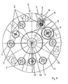
- Expansion segments 2 are on the folding cylinder 1 arranged. Outer surfaces 3 of the expansion segments 2 form the effective one Diameter of the folding cylinder 1.
- the expansion segments 2 are over Support elements 4 mounted on an eccentric spindle 5.
- the eccentric spindle 5 is not shown in more detail, arranged between carrier elements 6 on the folding cylinder 1.
- a drive wheel 7 arranged (see Fig. 2).
- tension rollers 8 are arranged, with a tension roller 8 with a Gear 9 is connected.
- the tensioning rollers 8 are preferably stationary arranged.
- the folding cylinder 1 is supported on a shaft 10. On the shaft 10 is a central one Drive wheel 11 rotatably mounted.
- the central drive wheel 11 stands with the Gear wheel 9 in connection with an endless drive means 12.
- the Drive wheels 7 and the tension rollers 8 are over another endless Drive means 13, here referred to as adjusting means 13, in connection.
- the Drive wheels 7 and tensioning rollers 8 are at least partially from the adjusting means 13 entwined.
- the central drive wheel 11, not shown, is connected to a drive.
- the position of this can be changed by optionally rotating the eccentric spindle 5 so that the support elements 4 arranged on the eccentric spindle 5 are radial be moved and thus a process of the expansion segments 2 in Allow adjustment direction 14 inwards or outwards. In this way it is effective outer diameter of the folding cylinder 1 adjustable.
Landscapes
- Engineering & Computer Science (AREA)
- Mechanical Engineering (AREA)
- Folding Of Thin Sheet-Like Materials, Special Discharging Devices, And Others (AREA)
Abstract
Description
- Fig. 1:
- eine Ansicht des Falzzylinders und
- Fig. 2:
- eine Seitenansicht des Falzzylinders nach Fig.1, bei dem zur besseren Darstellung nur ein Trägerelement gezeigt ist.
- 1
- Falzzylinder
- 2
- Expansions-Segment
- 3
- Außenfläche
- 4
- Stützelemente
- 5
- Exzenterspindel
- 6
- Trägerelement
- 7
- Antriebsrad
- 8
- Spannrolle
- 9
- Übersetzungsrad
- 10
- Welle
- 11
- Zentrales Antriebsrad
- 12
- Antriebsmittel
- 13
- Verstellmittel
- 14
- Verstellrichtung
Claims (6)
- Antrieb für Expansions-Segmente (2) zur Durchmesserverstellung am Falzzylinder (1), wobei die Expansions-Segmente (2) auf angetriebenen Exzenterspindeln (5) zwischen Trägerelemente (6) angeordnet sind, dadurch gekennzeichnet, dass an den Exzenterspindeln (5) Antriebsräder (7) angeordnet sind, die von einem endlosen Verstellmittel (13) zumindest teilweise umschlungen sind und das Verstellmittel (13) antreibbar ist.
- Antrieb nach Anspruch 1, dadurch gekennzeichnet, dass zwischen den Antriebsrädern (7) Spannrollen (8) angeordnet sind, wobei die Spannrollen (8) vom Verstellmittel (13) zumindest teilweise umschlungen sind.
- Antrieb nach Anspruch 1 oder 2, dadurch gekennzeichnet, dass der Antrieb des Verstellmittels (13) über ein endloses Antriebsmittel (12) erfolgt, welches um eine der Spannrollen (8) und um ein angetriebenes zentrales Antriebsrad (11) angeordnet ist, wobei das zentrale Antriebsrad (11) koaxial zum Falzzylinder (1) angeordnet ist.
- Antrieb nach Anspruch 3, dadurch gekennzeichnet, dass die mit dem Antriebsmittel (12) in Verbindung stehende Spannrolle (8) mit einem Übersetzungsrad (9) ausgestaltet ist.
- Antrieb nach einem der Ansprüche 2 bis 4, dadurch gekennzeichnet, dass die Spannrollen (8) stationär angeordnet sind.
- Antrieb nach einem der vorhergehenden Ansprüche, dadurch gekennzeichnet, dass das Antriebsmittel (12) und das Verstellmittel (13) als Kette oder Zahnriemen ausgestaltet sind.
Applications Claiming Priority (2)
| Application Number | Priority Date | Filing Date | Title |
|---|---|---|---|
| DE2002120109 DE10220109B4 (de) | 2002-05-04 | 2002-05-04 | Antrieb für Expansions-Segmente zur Durchmesserverstellung am Falzzylinder |
| DE10220109 | 2002-05-04 |
Publications (3)
| Publication Number | Publication Date |
|---|---|
| EP1359010A2 true EP1359010A2 (de) | 2003-11-05 |
| EP1359010A3 EP1359010A3 (de) | 2008-06-25 |
| EP1359010B1 EP1359010B1 (de) | 2011-10-19 |
Family
ID=28799017
Family Applications (1)
| Application Number | Title | Priority Date | Filing Date |
|---|---|---|---|
| EP20030009691 Expired - Lifetime EP1359010B1 (de) | 2002-05-04 | 2003-04-30 | Durchmesserverstellung am Falzzylinger |
Country Status (2)
| Country | Link |
|---|---|
| EP (1) | EP1359010B1 (de) |
| DE (1) | DE10220109B4 (de) |
Citations (3)
| Publication number | Priority date | Publication date | Assignee | Title |
|---|---|---|---|---|
| DE3821442A1 (de) | 1987-06-24 | 1989-01-05 | Mitsubishi Heavy Ind Ltd | Vorrichtung zum durchmessereinstellen einer falttrommel einer rotationspresse |
| US5313883A (en) | 1993-04-15 | 1994-05-24 | Rockwell International Corporation | Printing press with a dynamic expansion band adjusting mechanism |
| DE10110117A1 (de) | 2000-04-18 | 2001-10-25 | Heidelberger Druckmasch Ag | Falzzylinder mit einem Expansions-Segment |
Family Cites Families (2)
| Publication number | Priority date | Publication date | Assignee | Title |
|---|---|---|---|---|
| DE2530365C3 (de) * | 1975-07-08 | 1979-05-17 | Maschinenfabrik Augsburg-Nuernberg Ag, 8900 Augsburg | Einrichtung zur Durchmesserverstellung eines Zylinders |
| DE19522903A1 (de) * | 1995-06-23 | 1997-01-02 | Roland Man Druckmasch | Falzzylinder |
-
2002
- 2002-05-04 DE DE2002120109 patent/DE10220109B4/de not_active Expired - Fee Related
-
2003
- 2003-04-30 EP EP20030009691 patent/EP1359010B1/de not_active Expired - Lifetime
Patent Citations (3)
| Publication number | Priority date | Publication date | Assignee | Title |
|---|---|---|---|---|
| DE3821442A1 (de) | 1987-06-24 | 1989-01-05 | Mitsubishi Heavy Ind Ltd | Vorrichtung zum durchmessereinstellen einer falttrommel einer rotationspresse |
| US5313883A (en) | 1993-04-15 | 1994-05-24 | Rockwell International Corporation | Printing press with a dynamic expansion band adjusting mechanism |
| DE10110117A1 (de) | 2000-04-18 | 2001-10-25 | Heidelberger Druckmasch Ag | Falzzylinder mit einem Expansions-Segment |
Also Published As
| Publication number | Publication date |
|---|---|
| DE10220109A1 (de) | 2003-11-20 |
| EP1359010B1 (de) | 2011-10-19 |
| EP1359010A3 (de) | 2008-06-25 |
| DE10220109B4 (de) | 2007-04-05 |
Similar Documents
| Publication | Publication Date | Title |
|---|---|---|
| EP1845046B1 (de) | Falzanleger mit Vorrichtung zum Rillen des Bogens | |
| DE2756884A1 (de) | Vorrichtung zum herstellen mehrseitiger hefte aus einer endlosen bedruckten papierbahn | |
| DE3821442C2 (de) | ||
| CH678510A5 (de) | ||
| DE602004012202T2 (de) | Verfahren und Vorrichtung für das Überlappung von Bogen | |
| DE19716628C2 (de) | Verfahren und Vorrichtung zum Querfalzen von Signaturen | |
| EP1136411A2 (de) | Falzapparat mit kombiniertem Schneid- und Klemmzylinder | |
| WO2003070612A1 (de) | Falzapparat mit einem ersten und einem zweiten teilzylinder und ein verfahren zum betrieb eines solchen falzapparates | |
| DE10211108A1 (de) | Falzapparat mit gruppenweise verstellbaren Falzklappen | |
| CH696537A5 (de) | Signaturentransportvorrichtung. | |
| EP1359010B1 (de) | Durchmesserverstellung am Falzzylinger | |
| CH696538A5 (de) | Signaturenübergabevorrichtung. | |
| DE2634108C3 (de) | Räderfalzapparat | |
| DE19709485C2 (de) | Verfahren zum abschnittweisen Schneiden einer Bedruckstoffbahn in Längsrichtung und Schneideinrichtung hierfür | |
| DE3149226C2 (de) | Transportvorrichtung für Signaturbögen, Lagen o.ä. | |
| CH695767A5 (de) | Bedruckstoff verarbeitende Maschine mit einer Transportbandeinrichtung. | |
| EP1403034B1 (de) | Wellpappe-Anlage | |
| EP1818300B1 (de) | Querfalzeinrichtung eines Falzapparats einer Druckmaschine | |
| DE10261257B4 (de) | Antriebseinheit von Bearbeitungsstationen einer Bodenlegevorrichtung | |
| EP0581179B1 (de) | Vorrichtung zur Korrektur des Schnittregisters | |
| EP0734858B1 (de) | Bogenführungstrommel mit verstellbarer Mantelfläche | |
| EP1810799A1 (de) | Vorrichtungen zur Bearbeitung einer laufenden Materialbahn | |
| DE102008000057B4 (de) | Zugwalzenanordnung | |
| DE10155037A1 (de) | Falzapparat mit einer Führungseinrichtung | |
| DE19620603C1 (de) | Kurvengetriebe für Druckmaschinen mit einem periodisch umlaufenden Abtriebsglied |
Legal Events
| Date | Code | Title | Description |
|---|---|---|---|
| PUAI | Public reference made under article 153(3) epc to a published international application that has entered the european phase |
Free format text: ORIGINAL CODE: 0009012 |
|
| AK | Designated contracting states |
Kind code of ref document: A2 Designated state(s): AT BE BG CH CY CZ DE DK EE ES FI FR GB GR HU IE IT LI LU MC NL PT RO SE SI SK TR |
|
| AX | Request for extension of the european patent |
Extension state: AL LT LV MK |
|
| PUAL | Search report despatched |
Free format text: ORIGINAL CODE: 0009013 |
|
| AK | Designated contracting states |
Kind code of ref document: A3 Designated state(s): AT BE BG CH CY CZ DE DK EE ES FI FR GB GR HU IE IT LI LU MC NL PT RO SE SI SK TR |
|
| AX | Request for extension of the european patent |
Extension state: AL LT LV MK |
|
| RAP1 | Party data changed (applicant data changed or rights of an application transferred) |
Owner name: MANROLAND AG |
|
| 17P | Request for examination filed |
Effective date: 20081220 |
|
| AKX | Designation fees paid |
Designated state(s): CH DE FR GB LI NL |
|
| 17Q | First examination report despatched |
Effective date: 20090205 |
|
| GRAP | Despatch of communication of intention to grant a patent |
Free format text: ORIGINAL CODE: EPIDOSNIGR1 |
|
| GRAS | Grant fee paid |
Free format text: ORIGINAL CODE: EPIDOSNIGR3 |
|
| GRAA | (expected) grant |
Free format text: ORIGINAL CODE: 0009210 |
|
| AK | Designated contracting states |
Kind code of ref document: B1 Designated state(s): CH DE FR GB LI NL |
|
| REG | Reference to a national code |
Ref country code: GB Ref legal event code: FG4D Free format text: NOT ENGLISH |
|
| REG | Reference to a national code |
Ref country code: CH Ref legal event code: NV Representative=s name: E. BLUM & CO. AG PATENT- UND MARKENANWAELTE VSP Ref country code: CH Ref legal event code: EP |
|
| REG | Reference to a national code |
Ref country code: DE Ref legal event code: R096 Ref document number: 50314015 Country of ref document: DE Effective date: 20111222 |
|
| REG | Reference to a national code |
Ref country code: NL Ref legal event code: T3 |
|
| PGFP | Annual fee paid to national office [announced via postgrant information from national office to epo] |
Ref country code: DE Payment date: 20120629 Year of fee payment: 10 |
|
| REG | Reference to a national code |
Ref country code: DE Ref legal event code: R081 Ref document number: 50314015 Country of ref document: DE Owner name: MANROLAND WEB SYSTEMS GMBH, DE Free format text: FORMER OWNER: MAN ROLAND DRUCKMASCHINEN AG, 63075 OFFENBACH, DE Effective date: 20111028 Ref country code: DE Ref legal event code: R081 Ref document number: 50314015 Country of ref document: DE Owner name: MANROLAND WEB SYSTEMS GMBH, DE Free format text: FORMER OWNER: MANROLAND AG, 63075 OFFENBACH, DE Effective date: 20120626 |
|
| PLBE | No opposition filed within time limit |
Free format text: ORIGINAL CODE: 0009261 |
|
| STAA | Information on the status of an ep patent application or granted ep patent |
Free format text: STATUS: NO OPPOSITION FILED WITHIN TIME LIMIT |
|
| PGFP | Annual fee paid to national office [announced via postgrant information from national office to epo] |
Ref country code: GB Payment date: 20120629 Year of fee payment: 10 |
|
| 26N | No opposition filed |
Effective date: 20120720 |
|
| REG | Reference to a national code |
Ref country code: DE Ref legal event code: R097 Ref document number: 50314015 Country of ref document: DE Effective date: 20120720 |
|
| PGFP | Annual fee paid to national office [announced via postgrant information from national office to epo] |
Ref country code: FR Payment date: 20120806 Year of fee payment: 10 |
|
| PGFP | Annual fee paid to national office [announced via postgrant information from national office to epo] |
Ref country code: NL Payment date: 20120710 Year of fee payment: 10 |
|
| REG | Reference to a national code |
Ref country code: NL Ref legal event code: V1 Effective date: 20131101 |
|
| REG | Reference to a national code |
Ref country code: CH Ref legal event code: PL |
|
| GBPC | Gb: european patent ceased through non-payment of renewal fee |
Effective date: 20130430 |
|
| PG25 | Lapsed in a contracting state [announced via postgrant information from national office to epo] |
Ref country code: LI Free format text: LAPSE BECAUSE OF NON-PAYMENT OF DUE FEES Effective date: 20130430 Ref country code: DE Free format text: LAPSE BECAUSE OF NON-PAYMENT OF DUE FEES Effective date: 20131101 Ref country code: GB Free format text: LAPSE BECAUSE OF NON-PAYMENT OF DUE FEES Effective date: 20130430 Ref country code: CH Free format text: LAPSE BECAUSE OF NON-PAYMENT OF DUE FEES Effective date: 20130430 |
|
| REG | Reference to a national code |
Ref country code: FR Ref legal event code: ST Effective date: 20131231 |
|
| REG | Reference to a national code |
Ref country code: DE Ref legal event code: R119 Ref document number: 50314015 Country of ref document: DE Effective date: 20131101 |
|
| PG25 | Lapsed in a contracting state [announced via postgrant information from national office to epo] |
Ref country code: NL Free format text: LAPSE BECAUSE OF NON-PAYMENT OF DUE FEES Effective date: 20131101 Ref country code: FR Free format text: LAPSE BECAUSE OF NON-PAYMENT OF DUE FEES Effective date: 20130430 |