EP1357573A2 - Vorrichtung zur Herstellung einer fluoreszenten Schicht - Google Patents
Vorrichtung zur Herstellung einer fluoreszenten Schicht Download PDFInfo
- Publication number
- EP1357573A2 EP1357573A2 EP03252586A EP03252586A EP1357573A2 EP 1357573 A2 EP1357573 A2 EP 1357573A2 EP 03252586 A EP03252586 A EP 03252586A EP 03252586 A EP03252586 A EP 03252586A EP 1357573 A2 EP1357573 A2 EP 1357573A2
- Authority
- EP
- European Patent Office
- Prior art keywords
- nozzle
- material paste
- fluorescent material
- fluorescent
- fluorescent layer
- Prior art date
- Legal status (The legal status is an assumption and is not a legal conclusion. Google has not performed a legal analysis and makes no representation as to the accuracy of the status listed.)
- Ceased
Links
Images




Classifications
-
- H—ELECTRICITY
- H01—ELECTRIC ELEMENTS
- H01J—ELECTRIC DISCHARGE TUBES OR DISCHARGE LAMPS
- H01J9/00—Apparatus or processes specially adapted for the manufacture, installation, removal, maintenance of electric discharge tubes, discharge lamps, or parts thereof; Recovery of material from discharge tubes or lamps
- H01J9/20—Manufacture of screens on or from which an image or pattern is formed, picked up, converted or stored; Applying coatings to the vessel
- H01J9/233—Manufacture of photoelectric screens or charge-storage screens
-
- H—ELECTRICITY
- H01—ELECTRIC ELEMENTS
- H01J—ELECTRIC DISCHARGE TUBES OR DISCHARGE LAMPS
- H01J9/00—Apparatus or processes specially adapted for the manufacture, installation, removal, maintenance of electric discharge tubes, discharge lamps, or parts thereof; Recovery of material from discharge tubes or lamps
- H01J9/20—Manufacture of screens on or from which an image or pattern is formed, picked up, converted or stored; Applying coatings to the vessel
- H01J9/22—Applying luminescent coatings
- H01J9/227—Applying luminescent coatings with luminescent material discontinuously arranged, e.g. in dots or lines
-
- B—PERFORMING OPERATIONS; TRANSPORTING
- B05—SPRAYING OR ATOMISING IN GENERAL; APPLYING FLUENT MATERIALS TO SURFACES, IN GENERAL
- B05D—PROCESSES FOR APPLYING FLUENT MATERIALS TO SURFACES, IN GENERAL
- B05D1/00—Processes for applying liquids or other fluent materials
- B05D1/26—Processes for applying liquids or other fluent materials performed by applying the liquid or other fluent material from an outlet device in contact with, or almost in contact with, the surface
-
- B—PERFORMING OPERATIONS; TRANSPORTING
- B05—SPRAYING OR ATOMISING IN GENERAL; APPLYING FLUENT MATERIALS TO SURFACES, IN GENERAL
- B05D—PROCESSES FOR APPLYING FLUENT MATERIALS TO SURFACES, IN GENERAL
- B05D5/00—Processes for applying liquids or other fluent materials to surfaces to obtain special surface effects, finishes or structures
- B05D5/06—Processes for applying liquids or other fluent materials to surfaces to obtain special surface effects, finishes or structures to obtain multicolour or other optical effects
- B05D5/061—Special surface effect
Definitions
- the present invention relates to an apparatus for forming a fluorescent layer in a plasma display panel and, more particularly, to a fluorescent layer forming apparatus including an improved nozzle.
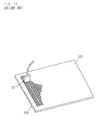
- the conventional fluorescent layer forming apparatus includes a dispenser 201 which has a plurality of ejection ports generally linearly arranged at predetermined intervals.
- a fluorescent material paste 207 prepared by dispersing fluorescent particles in a liquid medium is ejected from the dispenser 201 through a mask 226 into linear recesses defined between plural barrier ribs 224 arranged parallel to each other on a rear substrate 220, and heat-treated for formation of fluorescent layers 225.
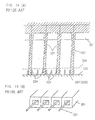
- Figs. 13 A conventional fluorescent layer forming apparatus disclosed in Japanese Unexamined Patent Publication No. H11-204032 (1999) will be described with reference to Figs. 13, 14(A) and 14(B).
- the conventional fluorescent layer forming apparatus includes a dispenser 201 which has a plurality of ejection ports generally linearly arranged at predetermined intervals.
- a fluorescent material paste 207 prepared by dispersing fluorescent particles in a liquid medium is ejected from the dispenser 201 through a mask 226 into linear recesses defined between plural barrier ribs 224
- the dispenser 201 includes fine rod-shaped guides 221 which respectively project from the ejection ports generally centrally of the ejection ports.
- the fluorescent material paste 207 is ejected along the guides 221, while the dispenser 201 is moved relative to the substrate 220.
- the fluorescent layers 225 are formed in the linear recesses between the barrier ribs 224.
- the fluorescent material paste which has a high viscosity and a low surface tension unlike water is attracted to the guides 221 and falls vertically downward.
- the guides 221 are each composed of a hair or a polyamide filament, the fluorescent material paste can be ejected with the guides 221 kept in contact with the bottoms of the recesses.
- the conventional fluorescent layer forming apparatus can assuredly apply the fluorescent material paste into the recesses.
- the fluorescent material paste is simply ejected along the guides from the ejection ports. At this time, the fluorescent material paste is liable to clot around the guides to form relatively large clots, depending on the viscosity of the fluorescent material paste. As a result, the fluorescent material paste is likely to adhere onto top edges of the barrier ribs or to enter recesses adjacent to the intended recesses (thereby to be mixed in different color fluorescent material pastes applied in the adjacent recesses). Thus, the conventional fluorescent layer forming apparatus fails to accurately form the fluorescent layers.
- a fluorescent layer forming apparatus for applying a fluorescent material paste into a recess defined between barrier ribs formed on a substrate for formation of a fluorescent layer in a plasma display panel production process, the apparatus comprising: a nozzle for ejecting the fluorescent material paste; and a plurality of fine attachments provided at one end of the nozzle with distal end portions thereof being arranged in convergent relation, whereby the fluorescent material paste is ejected along the plurality of fine attachments so as to be applied onto a predetermined position in the recess for the formation of the fluorescent layer.
- proximal ends of the fine attachments are fixed to the nozzle, and the distal ends of the fine attachments are arranged in convergent relation.
- the front of the fluorescent material paste moves along the plurality of fine attachments arranged in convergent relation. Therefore, the fluorescent material paste is convergently retained between the fine attachments and ejected from the nozzle without formation of a clot.
- the fluorescent layer can accurately be formed in the intended recess defined between the barrier ribs without adhesion thereof onto the top edges of the barrier ribs.
- the fine attachments are adapted to control the eject line of the fluorescent material paste for guiding the fluorescent material paste to a predetermined position in the recess.
- Specific example of the material for the fine attachments includes stainless.
- the inventive fluorescent layer forming apparatus may be adapted to eject the fluorescent material paste with the distal ends of the fine attachments kept in contact with the bottom of the recess defined between the barrier ribs.
- the nozzle is scanned for the application of the fluorescent material paste, while the distal ends of the fine attachments fixed to the nozzle are kept in contact with the bottom of the recess. Therefore, the fluorescent material paste is guided along the fine attachments into the recess between the barrier ribs.
- the fluorescent layer can more accurately be formed in the intended recess between the barrier ribs.
- the fine attachments may each be composed of a material having a wetting contact angle of not greater than 60 degrees with respect to the fluorescent material paste.
- the fluorescent material paste supplied to the nozzle smoothly moves along the fine attachments composed of the material having a wetting contact angle of not greater than 60 degrees with respect to the fluorescent material paste without stagnation, and is ejected at a predetermined ejection rate from the nozzle without formation of a clot.
- the fluorescent layer thus formed has a uniform thickness.
- the fluorescent material paste may have a viscosity of 5 Pa ⁇ s to 50 Pa ⁇ s at a sheer rate of 4 s -1 .
- sheer rate refers to a velocity gradient of a flux of the fluorescent material paste. More specifically, it refers to a velocity gradient determined by a flux of the fluorescent material past being ejected from the nozzle and a flux of the fluorescent material paste retained in a retaining portion of the nozzle at a position from the center line of the nozzle a predetermined distance.
- An appropriate value of the viscosity of the fluorescent material paste can be determined in accordance with Hagen-Poiseuille's formula using the inner diameter of the nozzle, the amount of the fluorescent material paste to be ejected, the pressure under which the fluorescent material paste is to be ejected and the like as parameters.
- the fluorescent material paste having a viscosity of 5 Pa ⁇ s to 50 Pa ⁇ s at a sheer rate of 4 s -1 is supplied to the nozzle and, therefore, smoothly moves along the fine attachments without stagnation and is ejected at a predetermined ejection rate from the nozzle without formation of a clot.
- the fluorescent layer thus formed has a uniform thickness.
- a fluorescent layer forming apparatus for applying a fluorescent material paste into a recess defined between barrier ribs formed on a substrate for formation of a fluorescent layer in a plasma display panel production process, the apparatus comprising: a nozzle for ejecting the fluorescent material paste; and a plurality of fine attachments provided at one end of the nozzle as projecting from the nozzle; wherein portions of the fine attachments projecting from the nozzle each have a length not smaller than the radius of the nozzle.
- the portions of the fine attachments projecting from the nozzle each have a length not smaller than the radius of the nozzle, so that the fluorescent material paste can smoothly and accurately be applied dropwise into the recess without deflection thereof around the outer periphery of the fine attachments. Therefore, the fluorescent material paste can smoothly be applied dropwise into the recess continuously for a long period of time.
- a fluorescent layer forming apparatus for applying a fluorescent material paste into a recess defined between barrier ribs formed on a substrate for formation of a fluorescent layer in a plasma display panel production process, the apparatus comprising: a nozzle having an outlet for ejecting the fluorescent material paste; and a plurality of fine attachments provided at one end of the nozzle, the fine attachments defining a retention portion having a greater cross sectional area than the outlet of the nozzle and an ejection port having a smaller cross sectional area than the retention portion.
- the retention portion having a greater cross sectional area than the outlet of the nozzle and the ejection port having a smaller cross sectional area than the retention portion are defined by the fine attachments fixed to the end of the nozzle. Therefore, the fluorescent material paste can accurately be applied into the recess. Since the fluorescent material paste is once retained in the retention portion and then ejected, the fluorescent material paste can smoothly be supplied even if the ejection rate of the fluorescent material paste is changed.
- the inventive fluorescent layer forming apparatus may further comprise a filter provided above a fluorescent material paste supply port of the nozzle, wherein proximal ends of the fine attachments are fixed to the filter.
- the filter provided above the fluorescent material paste supply port of the nozzle has a predetermined mesh size, so that particles greater in size than the predetermined mesh size can be filtered out for prevention of clogging of the nozzle before the fluorescent material paste is supplied into the nozzle.
- stable formation of the fluorescent layer can be ensured for a long period of time.
- FIG. 1 illustrates the entire fluorescent layer forming apparatus according to this embodiment
- Figs. 2(A) and 2(B) illustrate, in detail, a dispenser and a nozzle of the fluorescent layer forming apparatus shown in Fig. 1.
- Fig. 3 illustrates a plasma display panel having fluorescent layers to be formed by means of the fluorescent layer forming apparatus according to this embodiment.
- the fluorescent layer forming apparatus includes a dispenser 1 for ejecting a fluorescent material paste 7 into recesses defined between plural barrier ribs arranged parallel to each other on a surface of a substrate (e.g., a rear substrate) of the plasma display panel (hereinafter referred to simply as "PDP"), and a pressure tank 3 for storing the fluorescent material paste 7 and supplying the fluorescent material paste 7 into the dispenser 1 under pressure.
- the dispenser 1 and the pressure tank 3 are connected by a pipe 6.
- the construction of the fluorescent layer forming apparatus is not limited to this construction.
- the dispenser 1 includes a nozzle 2 disposed at a distal end thereof and serving as an ejection port for ejecting the fluorescent material paste 7.
- the nozzle 2 has a cavity extending longitudinally therethrough and having a predetermined inner diameter.
- two fine attachments 21 are fixed to the outer periphery of the nozzle 2 with proximal ends thereof opposed to each other and with distal end portions thereof arranged in convergent relation.
- the fine attachments 21 are arranged in convergent relation, but the distal ends thereof are spaced a very small distance from each other.
- the pressure tank 3 is adapted to store the fluorescent material paste 7 and supply the fluorescent material paste 7 into the dispenser 1 in accordance with the internal gas pressure thereof.
- the pressure tank 3 is connected to a gas system (not shown) for supplying gas for pressurization of the pressure tank 3, and a gas pressure regulator 4 is provided between the gas system and the pressure tank 3 for regulating the internal gas pressure of the pressure tank 3.
- a pressure gage 5 for measuring a gas supply pressure is provided between the gas pressure regulator 4 and the pressure tank 3. The gas supply pressure can be adjusted by the gas pressure regulator 4 with reference to a pressure level measured by the pressure gage 5.
- the fluorescent material paste 7 is prepared by dissolving a natural or synthetic cellulose resin in an organic solvent and dispersing fluorescent material particles having an average particle diameter of 3 ⁇ m in the resulting resin solution with or without a dispersant.
- the fluorescent material paste 7 comprises 20 to 30% of the fluorescent material particles, 5 to 10 wt% of the cellulose resin and 50 to 60% of the organic solvent and, optionally, 0.1 to 1 % of the dispersant.
- the fluorescent material paste 7 thus prepared has a viscosity of 100 to 200 poise.
- the PDP 100 having the fluorescent layers to be formed by means of the fluorescent layer forming apparatus is, for example, a common PDP of triode discharge type as shown in Fig. 3, and includes a front substrate 110 on which a plurality of main electrodes (sustainable discharge electrode) 111 are arranged generally parallel to each other, and a rear substrate 120 on which a plurality of address electrodes 121 arranged parallel to each other perpendicularly to the main electrodes 111.
- the front substrate 110 and the rear substrate 120 are combined in intimate contact with each other via a seal (not shown).
- a plurality of linear barrier ribs 124 are provided on the rear substrate 120 of the common triode-discharge-type PDP 100 to define recesses therebetween.
- the fluorescent layer forming apparatus is adapted to apply the fluorescent material paste 7 into these recesses (in Fig. 3, the fluorescent layers 125 (125R, 125G, 125B) are already formed).
- the plurality of address electrodes 121 are arranged perpendicularly to the main electrodes 111 on a planar glass substrate, and covered with a transparent dielectric layer 123.
- the linear barrier ribs 124 are provided between the address electrodes 121 for isolation of electric discharge.
- Red, green and blue fluorescent layers 125 (125R, 125G, 125B) to be formed by means of the fluorescent layer forming apparatus are provided on upper surface portions of the dielectric layer 123 and side walls of the barrier ribs 124.
- the fluorescent layers 125 for only one pixel are shown in Fig. 3, a multiplicity of fluorescent layers are provided according to the number of pixels of the PDP.
- the rear substrate 120 typically has a thickness of about 2 mm to about 3 mm, and the transparent dielectric layer 123 typically has a thickness of several tens ⁇ m.
- the barrier ribs 124 typically each have a thickness of 100 ⁇ m to 200 ⁇ m.
- the fluorescent material paste 7 supplied into the dispenser 1 flows through the cavity of the dispenser 1 into the nozzle 2.
- the front of the fluorescent material paste 7 passes through the nozzle 2, then convergently moves along the fine attachments 21, and passes through a gap defined between the distal ends of the fine attachments 21 to reach the predetermined point in the recess on the rear substrate 120.
- the distal end of the nozzle 2 is scanned along the recess from one end to the other, while the fluorescent material paste 7 is continuously supplied into the dispenser 1.
- the fluorescent material paste 7 is continuously applied into the recess between the two adjacent barrier ribs 124, whereby a linear fluorescent layer 125 is formed in the recess.
- a plurality of fluorescent layers 125 can be formed in substantially the same manner by employing a dispenser of a multi-nozzle structure including a plurality of nozzles.
- An ejection rate (the amount of the fluorescent material paste 7 to be ejected per unit time by the nozzle 2) is proportional to the gas pressure in the pressure tank 3 and, therefore, can be adjusted by means of the gas pressure regulator 4.
- the gas pressure should be adjusted, depending on the viscosity of the paste, the nozzle movement rate and a distance between the distal ends of the fine attachments and the rear substrate 120.
- the gas pressure (ejection pressure) is set at about 0.3 MPa for properly forming the fluorescent layer 125, where the viscosity of the paste is 20 Pa ⁇ s, the nozzle movement rate is 40 mm/s and the distance between the distal ends of the fine attachments and the rear substrate 120 is 200 ⁇ m.
- the two fine attachments 21 are fixed to the outer periphery of the distal end portion of the nozzle 2 with the proximal ends thereof opposed to each other and with the distal end portions thereof arranged in convergent relation.
- the front of the fluorescent material paste 7 moves along the fine attachments 21 arranged in convergent relation. Therefore, the fluorescent material paste 7 is convergently ejected from the nozzle 2.
- the fluorescent layer 125 can accurately be formed in the intended recess between the barrier ribs 124 without formation of a clot and without adhesion of the fluorescent material paste 7 onto the top edges of the barrier ribs 124.
- the fine attachments may be composed of a material having a contact angle of not greater than 60 degrees with respect to the fluorescent material paste 7. In this case, the fluorescent material paste can more smoothly move along the fine attachments without formation of clot.
- the material of the fine attachment may be stainless, for example.
- FIG. 4(A) and 4(B) illustrate, in detail, a nozzle of the fluorescent layer forming apparatus according to this embodiment.
- the fluorescent layer forming apparatus has substantially the same construction as the first embodiment, except that two opposed fine plate attachments 22 are fixed to the outer periphery of a distal end portion of the nozzle 2 with distal end portions thereof arranged in convergent relation as shown in Fig. 4(A).
- the fine plate attachments 22 are located in a recess defined between two adjacent barrier ribs 124 in opposed relation to the barrier ribs 124.
- Opposed inner surfaces of the fine plate attachments 22 each have a higher wettability, and outer surfaces of the fine plate attachments 22 opposite from the opposed inner surfaces each have a lower wettability.
- the fluorescent material paste 7 supplied through the nozzle 2 flows in contact with the highly wettable opposed inner surfaces of the fine plate attachments 22, and convergently ejected from a gap defined between the fine plate attachments 22.
- the distal ends of the fine plate attachments 22 are each rounded in a semicircular shape. Hence, there is no possibility that the fine plate attachments 22 scrape the bottom of the recess on the rear substrate 120 when the nozzle 2 is scanned along the recess with the fine plate attachments 22 kept in contact with the bottom of the recess.
- the fluorescent material paste 7 is forced out of the pressure tank 3 to be supplied into the dispenser 1 through the pipe 6.
- the fluorescent material paste 7 supplied into the dispenser 1 flows through the cavity of the dispenser 1 into the nozzle 2.
- the front of the fluorescent material paste 7 passes through the nozzle 2, then convergently moves along the fine plate attachments 22, and passes through the gap defined between the distal ends of the fine plate attachments 22 (see Fig. 4(B)) to reach a predetermined point in the recess on the rear substrate 120.
- the distal end of the nozzle 2 is scanned along the recess from one end to the other, while the fluorescent material paste 7 is continuously supplied into the dispenser 1.
- the fluorescent material paste 7 is continuously applied into the recess between the two adjacent barrier ribs 124, whereby a linear fluorescent layer 125 is formed in the recess.
- the ejected fluorescent material paste 7 spreads in the recess only longitudinally of the barrier ribs 124 because the fine plate attachments 22 are arranged in opposed relation to the barrier ribs 124. This prevents the fluorescent material paste 7 from spreading across the barrier ribs. Therefore, the fluorescent material paste 7 is applied neither onto the top edges of the barrier ribs 124 nor into unintended adjacent recesses.
- the two opposed fine plate attachments 22 are fixed to the outer periphery of the distal end portion of the nozzle 2 of the dispenser 1 with the distal end portions thereof arranged in convergent relation.
- the fine plate attachments 22 are located in the recess in opposed relation to the barrier ribs 124.
- the front of the fluorescent material paste 7 moves along the fine attachments 21 arranged in convergent relation. Since the distal ends of the fine plate attachments 22 are kept in contact with the bottom of the recess on the rear substrate 120, the fluorescent material paste 7 is ejected directly into the recess.
- the fluorescent layer 125 can accurately be formed in the intended linear recess defined between the two adjacent barrier ribs 124 without formation of clots and without adhesion of the fluorescent material paste 7 onto the top edges of the barrier ribs 124. Even if the ejection rate of the fluorescent material paste is high, the fluorescent material paste 7 can be ejected into the recess only longitudinally of the barrier ribs 124. Therefore, the fluorescent material paste 7 is applied neither onto the top edges of the barrier ribs 124 nor into unintended adjacent recesses.
- FIG. 5(A) illustrates, in detail, a nozzle of the fluorescent layer forming apparatus according to this embodiment.
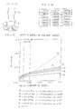
- Fig. 5(B) is a table showing a factor determined by the surface tension and density of a fluorescent material paste.
- Fig. 5(C) is a graph illustrating a relationship between the outer diameter of the nozzle and the length of fine attachments.
- the fluorescent layer forming apparatus has substantially the same construction as the first embodiment except for the construction of the fine attachments 21 fixed to the nozzle 2.
- Two pairs of opposed fine attachments are fixed to the nozzle 2 as extending linearly from the nozzle 2 but not in convergent relation as shown in Fig. 5(A), and portions of the fine attachments 21 projecting from the nozzle 2 each have a length not smaller than the radius of the nozzle 2.
- these fine attachments 21 are located in a recess defined between two adjacent barrier ribs 124 for formation of a fluorescent layer, one pair of opposed fine attachments 21 are arranged in opposed relation to the barrier ribs 124, and the other pair of opposed fine attachments 21 are arranged longitudinally of the barrier ribs 124.
- the fluorescent layer forming apparatus employs a dropwise application method for the application of the fluorescent material paste 7.
- a liquid droplet calmly drops from an end of a vertical pipe when its weight exceeds its surface tensile force.
- the nozzle has an outer diameter D
- the fluorescent material paste 7 has a density ⁇ , a surface tension ⁇ , a droplet mass m and a droplet radius R.
- an expression mg ⁇ ⁇ D ⁇ is satisfied.
- the fluorescent material paste 7 is prevented from deflecting around the fine attachments 21.
- the fluorescent material paste 7 can continuously smoothly be applied dropwise in the recess for a long period of time.
- the portions of the fine attachments 21 projecting from the nozzle 2 each have a length not smaller than the radius of the nozzle 2. Therefore, the fluorescent material paste 7 can accurately be applied in the recess. Since the fluorescent material paste 7 is prevented from deflecting around the fine attachments 21, the fluorescent material paste 7 can continuously smoothly be applied dropwise in the recess for a long period of time.
- a fluorescent layer forming apparatus according to a fourth embodiment of the present invention will be described with reference to Figs. 6(A) to 6(C), 7(A) and 7(B), which illustrate, in detail, a nozzle of the fluorescent layer forming apparatus according to this embodiment.
- the fluorescent layer forming apparatus has substantially the same construction as the first embodiment except for the construction of the fine attachments fixed to the nozzle 2. That is, two pairs of opposed fine attachments 24 as shown in Figs. 6(A) to 6(C) are fixed to the outer periphery of the nozzle 2.
- the fine attachments 24 each include an extension plate portion 24a extending longitudinally of the nozzle 2, a fan-shaped deflection plate portion 24b extending continuously from a distal edge of the extension portion 24a toward the center line of the nozzle 2, and a rod portion 24c extending from a distal end of the deflection portion 24b longitudinally of the nozzle 2.
- the fine attachments 24 When the fine attachments 24 are located in a recess defined between two adjacent barrier ribs 124 for formation of a fluorescent layer, one pair of opposed fine attachments are arranged in opposed relation to the barrier ribs 124 and the other pair of opposed fine attachments are arranged longitudinally of the barrier ribs 124.
- An internal space defined by the extension portions 24a and the deflection portions 24b serves as a retaining portion 24d, which retains the fluorescent material paste 7 supplied from the nozzle 2 and smoothly and accurately supplies the fluorescent material paste 7 into a space defined by the rod portions 24c.
- the cross sectional area S1 of a space (an inner portion of the retaining portion 24d) defined by the extension portions 24a, the cross sectional area S2 of the nozzle 2 and the cross sectional area S3 of the space defined by the rod portions 24c satisfy a relational expression S1 ⁇ S2>S3.
- the fluorescent material paste 7 is supplied into the dispenser 1.
- the fluorescent material paste 7 supplied into the dispenser 1 flows through the cavity of the dispenser 1 into the nozzle 2.
- the front of the fluorescent material paste 7 moves through the nozzle 2 to reach the extension portions 24a of the fine attachments 24.
- the space defined by the extension portions 24a has a cross sectional area S2 greater than the cross sectional area S1 of the nozzle 2 and partly opens laterally, so that the fluorescent material paste 7 can smoothly be introduced into the retaining portion 24d from the nozzle 2.
- the fluorescent material paste 7 introduced into the retaining portion 24d flows along the extension portions 24a, then along the deflection portions 24b and along the rod portions 24c.
- the fluorescent material paste 7 passes through the space defined by the rod portions 24c to reach a predetermined point in the recess on the rear substrate 120. Then, the fluorescent layer forming apparatus is operated in the same manner as in the first embodiment.
- the fine attachments 24 each including the extension portion 24a, the deflection portion 24b and the rod portion 24c are fixed to the nozzle 2.
- the one pair of opposed fine attachments 24 are arranged in opposed relation to the barrier ribs 124 and the other pair of opposed fine attachments 24 are arranged longitudinally of the barrier ribs 124.
- the fluorescent material paste 7 ejected from the nozzle 2 is retained in the retaining portion 24d defined by the extension portions 24a and the deflection portions 24b.
- the fluorescent material paste 7 can continuously be supplied into the space defined by the rod portions 24c from the retaining portion 24d defined by the extension portions 24a and the deflection portions 24b thereby to be more easily and more accurately applied into the recess without deflection thereof around the fine attachments and without adhesion thereof onto the outer periphery, as compared with a case where the nozzle 2 provided with only one pair of opposed fine attachments is moved along the barrier ribs for application of the fluorescent material paste 7 with the fine attachments being arranged in opposed relation to the barrier ribs (in this case, the fluorescent material paste deflects around the outer periphery of the fine attachments thereby to adhere onto the outer periphery).
- the fine attachments 24 of the fluorescent layer forming apparatus may each entirely have a rod shape as shown in Figs. 7(A) and 7(B), rather than partly have a plate shape.
- FIG. 8(A) to 8(C) illustrate, in detail, a nozzle of the fluorescent layer forming apparatus according to this embodiment.
- the fluorescent layer forming apparatus has substantially the same construction as the first embodiment except for the construction of the fine attachments fixed to the nozzle 2. As shown in Figs. 8(A) to 8(C), two pairs of opposed fine attachments 25 each having a curved plate shape are fixed to the nozzle 2. The fine attachments 25 are each twisted so that distal end portions thereof are angularly offset by 90 degrees from proximal end portions thereof.
- the fluorescent material paste 7 is supplied into the dispenser 1, and then flows through the cavity of the dispenser 1 into the nozzle 2.
- the front of the fluorescent paste 7 passes through the nozzle 2, then moves along the curved surfaces of the fine attachments 25, and passes through a gap defined by the distal ends of the fine attachments 25 to reach a predetermined point in a recess defined between two adjacent barrier ribs 124 on the rear substrate 120.
- the fluorescent layer forming apparatus is operated in the same manner as in the first embodiment.
- the fine attachments 25 each having a plate shape are fixed to the nozzle 2, and twisted so that the distal end portions thereof are angularly offset by 90 degrees from the proximal end portions thereof. Further, when the fine attachments 25 are located in the recess for the formation of the fluorescent layer, one pair of opposed fine attachments 25 are arranged in opposed relation to the barrier ribs and the other pair of opposed fine attachments 25 are arranged longitudinally of the barrier ribs. Since the nozzle 2 is surrounded by the four fine attachments 25, the fluorescent material paste 7 ejected from the nozzle 2 can be applied into the recess without adhesion thereof onto the outer periphery of the fine attachments 25. Even if the ejection rate of the fluorescent material paste is increased, the fine attachments 25 each twisted by 90 degrees give no resistance to the fluorescent material paste 7, so that the fluorescent material paste 7 can smoothly be applied into the recess.
- a first filter 11 having a first predetermined mesh size for filtering out particles greater in size than the first mesh size is provided above a fluorescent material paste supply port of the nozzle 2 in the cavity of the dispenser 1, and a second filter 12 having a second predetermined mesh size smaller than the first mesh size is provided between the first filter 11 and the supply port of the nozzle 2 in the dispenser 1.
- the proximal ends of the fine attachments 21 (or 22) are fixed to the second filter 12.
- the fluorescent material paste 7 is not directly supplied into the nozzle 2 from the pressure tank 3, but filtered by the first filter 11 for removal of particles greater in size than the first mesh size and by the second filter 12 for removal of particles greater in size than the second mesh size before being supplied into the nozzle 2.
- the fluorescent material paste 7 is supplied along the fine attachments 21 from the nozzle 2 of the dispenser 1 and ejected into the recess defined between the barrier ribs 124.
- the dispenser 1 is illustrated as having a multi-nozzle structure including a plurality of nozzles.
- the first and second mesh sizes of the first and second filters 11, 12 provided above the fluorescent material paste supply port of the nozzle 2 should be determined so as to filter out particles greater in size than the size of the fluorescent material particles in the fluorescent material paste 7.
- the fluorescent material paste 7 containing all the essential constituents including the fluorescent particles can be ejected along the fine attachments 21 (or 22) into the recess between the barrier ribs 124 for the formation of the fluorescent layer 125.
- the fluorescent material paste 7 continuously supplied into the nozzle 2 flows along the fine attachments 21 (or 22) arranged in convergent relation within the nozzle 2 thereby to be continuously ejected convergently from the nozzle 2.
- the fluorescent layer 125 can continuously be formed in the intended recess between the barrier ribs.
- a multiplicity of fine attachments of filaments or fine strips are fixed to the nozzle 2 in convergent relation as shown in Fig. 11.
- the front of the fluorescent material paste 7 moves along the multiplicity of fine attachments 23 arranged in convergent relation within the nozzle 2. Therefore, the fluorescent material paste 7 can assuredly convergently be ejected from the nozzle 2 into the intended recess without formation of clots.
- the fluorescent layer 125 can accurately be formed in the intended recess between the barrier ribs 124 without adhesion of the fluorescent material paste 7 onto the top edges of the barrier ribs 124.
- portions of the fine attachments projecting from the distal end of the nozzle 2 may have a length of not smaller than 500 ⁇ m.
- two pairs of opposed linear fine attachments 21(21 ⁇ , 21 ⁇ , 21 ⁇ , 21 ⁇ ) are fixed to the nozzle 2 as extending in non-convergent manner from the nozzle 2.
- One pair of opposed fine attachments 21 ⁇ , 21 ⁇ to be located longitudinally of the barrier ribs are composed of a material having a higher wettability, while the other pair of opposed fine attachments 21 ⁇ , 21 ⁇ to be located in opposed relation to the barrier ribs are composed of a material having a lower wettability.
- the fluorescent material paste 7 is biased toward the center line between the barrier ribs by the highly wettable fine attachments 21 ⁇ , 21 ⁇ arranged along a nozzle movement direction longitudinally of the barrier ribs. Further, the approach of the fluorescent material paste 7 to the barrier ribs is restricted by the less wettable fine attachments 21 ⁇ , 21 ⁇ arranged in opposed relation to the barrier ribs. Thus, the fluorescent material paste 7 can accurately be applied into the recess.
- the fine attachments may each have a square cross section as shown in Fig. 12(C). Alternatively, the fine attachments 21 may each have a cross section having acute-angled corners, or may each have an undulated peripheral surface. Even in this case, the fluorescent material paste 7 can accurately be introduced into the recess.
- the proximal ends of the plural fine attachments are fixed to the nozzle, and the distal end portions of the fine attachments are arranged in convergent relation.
- the front of the fluorescent material paste moves along the fine attachments, so that the fluorescent material paste is retained between the fine attachments and convergently ejected from the nozzle without formation of a clot.
- the fluorescent layer can accurately be formed in the intended recess between the barrier ribs without adhesion of the fluorescent material paste onto the top edges of the barrier ribs.
- the distal end of the nozzle is scanned along the recess for the application of the fluorescent material paste, while the distal ends of the fine attachments fixed to the nozzle are kept in contact with the bottom of the recess. Therefore, the fluorescent material paste is guided along the fine attachments thereby to be applied into the recess between the barrier ribs.
- the fluorescent layer can more accurately be formed in the intended recess between the barrier ribs.
- the fine attachments are each composed of a material having a contact angle of not greater than 60 degrees with respect to the fluorescent material paste. Therefore, the fluorescent material paste supplied into the nozzle smoothly moves along the fine attachments without stagnation, and is ejected at a predetermined ejection rate from the nozzle without formation of a clot.
- the fluorescent layer thus formed has a uniform thickness.
- the fluorescent material paste has a viscosity of 5 Pa ⁇ s to 50 Pa ⁇ s at a sheer rate of 4 s -1 . Therefore, the fluorescent material paste supplied into the nozzle smoothly moves along the fine attachments without stagnation, and is ejected at a predetermined ejection rate from the nozzle without formation of a clot.
- the fluorescent layer thus formed has a uniform thickness.
- the portions of the fine attachments projecting from the nozzle each have a length not smaller than the radius of the nozzle. Therefore, the fluorescent material paste can smoothly and accurately be applied dropwise into the recess without deflection thereof around the outer periphery of the fine attachments. Therefore, the fluorescent material paste can smoothly be applied dropwise into the recess continuously for a long period of time.
- the fine attachments fixed to the nozzle define the retention portion having a greater cross sectional area than the outlet of the nozzle, and the ejection port having a smaller cross sectional area than the retention portion. Therefore, the fluorescent material paste can accurately be applied into the recess. Since the fluorescent material paste is once retained in the retention portion and then ejected, the fluorescent material paste can smoothly be supplied even if the ejection rate of the fluorescent material paste is changed.
- the filter having a predetermined mesh size is provided above the fluorescent material paste supply port of the nozzle for filtering out particles greater in size than the predetermined mesh size. Therefore, particles greater in size than the predetermined mesh size can be filtered out for prevention of clogging of the nozzle, before the fluorescent material paste is supplied into the nozzle. Thus, stable formation of the fluorescent layer can be ensured for a long period of time.
Landscapes
- Engineering & Computer Science (AREA)
- Manufacturing & Machinery (AREA)
- Gas-Filled Discharge Tubes (AREA)
- Coating Apparatus (AREA)
- Formation Of Various Coating Films On Cathode Ray Tubes And Lamps (AREA)
- Application Of Or Painting With Fluid Materials (AREA)
Applications Claiming Priority (4)
| Application Number | Priority Date | Filing Date | Title |
|---|---|---|---|
| JP2002122963 | 2002-04-24 | ||
| JP2002122963 | 2002-04-24 | ||
| JP2002236057A JP4212318B6 (ja) | 2002-04-24 | 2002-08-13 | 蛍光体形成装置 |
| JP2002236057 | 2002-08-13 |
Publications (2)
| Publication Number | Publication Date |
|---|---|
| EP1357573A2 true EP1357573A2 (de) | 2003-10-29 |
| EP1357573A3 EP1357573A3 (de) | 2005-11-09 |
Family
ID=28793622
Family Applications (1)
| Application Number | Title | Priority Date | Filing Date |
|---|---|---|---|
| EP03252586A Ceased EP1357573A3 (de) | 2002-04-24 | 2003-04-24 | Vorrichtung zur Herstellung einer fluoreszenten Schicht |
Country Status (5)
| Country | Link |
|---|---|
| US (1) | US6758905B2 (de) |
| EP (1) | EP1357573A3 (de) |
| KR (1) | KR100730668B1 (de) |
| CN (1) | CN1259685C (de) |
| TW (1) | TWI237287B (de) |
Families Citing this family (3)
| Publication number | Priority date | Publication date | Assignee | Title |
|---|---|---|---|---|
| JP2005187712A (ja) * | 2003-12-26 | 2005-07-14 | Samsung Sdi Co Ltd | 塗布組成物及びその塗布方法並びにガス放電表示装置 |
| JP5583526B2 (ja) * | 2009-09-17 | 2014-09-03 | 日本発條株式会社 | 液剤塗布装置 |
| WO2021033689A1 (ja) * | 2019-08-19 | 2021-02-25 | 富士フイルム株式会社 | 電極用成形体の製造方法 |
Family Cites Families (10)
| Publication number | Priority date | Publication date | Assignee | Title |
|---|---|---|---|---|
| US2116863A (en) * | 1937-05-05 | 1938-05-10 | Solvent Machine Company | Spray and jet nozzle |
| US5002008A (en) * | 1988-05-27 | 1991-03-26 | Tokyo Electron Limited | Coating apparatus and method for applying a liquid to a semiconductor wafer, including selecting a nozzle in a stand-by state |
| JP3113212B2 (ja) * | 1996-05-09 | 2000-11-27 | 富士通株式会社 | プラズマディスプレイパネルの蛍光体層形成装置および蛍光体塗布方法 |
| KR100532729B1 (ko) * | 1996-12-17 | 2006-06-28 | 도레이 가부시끼가이샤 | 플라즈마디스플레이의제조방법및제조장치 |
| EP0884754B1 (de) * | 1996-12-17 | 2006-04-12 | Toray Industries, Inc. | Verfahren und vorrichtung zur herstellung von plasmaanzeige |
| US5851732A (en) * | 1997-03-06 | 1998-12-22 | E. I. Du Pont De Nemours And Company | Plasma display panel device fabrication utilizing black electrode between substrate and conductor electrode |
| US5820025A (en) * | 1997-03-20 | 1998-10-13 | Troudt; Kevin J. | Reversible spray tip holder |
| US6063339A (en) * | 1998-01-09 | 2000-05-16 | Cartesian Technologies, Inc. | Method and apparatus for high-speed dot array dispensing |
| JP3656387B2 (ja) | 1998-01-14 | 2005-06-08 | 松下電器産業株式会社 | カラー表示pdpの蛍光体形成方法および装置 |
| US20010032887A1 (en) * | 1999-02-19 | 2001-10-25 | Everett Alan L. | Precision dispensing tip and method |
-
2003
- 2003-04-22 TW TW092109395A patent/TWI237287B/zh not_active IP Right Cessation
- 2003-04-22 US US10/419,762 patent/US6758905B2/en not_active Expired - Fee Related
- 2003-04-23 KR KR1020030025634A patent/KR100730668B1/ko not_active Expired - Fee Related
- 2003-04-24 CN CNB031220614A patent/CN1259685C/zh not_active Expired - Fee Related
- 2003-04-24 EP EP03252586A patent/EP1357573A3/de not_active Ceased
Also Published As
| Publication number | Publication date |
|---|---|
| TW200402755A (en) | 2004-02-16 |
| US6758905B2 (en) | 2004-07-06 |
| CN1259685C (zh) | 2006-06-14 |
| JP2004006200A (ja) | 2004-01-08 |
| KR20030084684A (ko) | 2003-11-01 |
| US20030203099A1 (en) | 2003-10-30 |
| TWI237287B (en) | 2005-08-01 |
| KR100730668B1 (ko) | 2007-06-21 |
| JP4212318B2 (ja) | 2009-01-21 |
| EP1357573A3 (de) | 2005-11-09 |
| CN1453814A (zh) | 2003-11-05 |
Similar Documents
| Publication | Publication Date | Title |
|---|---|---|
| KR100855163B1 (ko) | 구금 및 액체의 도포 장치 및 도포 방법 | |
| DE69110958T2 (de) | Aufzeichnungsverfahren und Vorrichtung. | |
| JP4865893B2 (ja) | ダイヘッドおよび液体塗布装置 | |
| DE69413708T2 (de) | Vorrichtung und verfahren zum sprühen von flüssigkeiten | |
| DE69725264T2 (de) | Behälter zum Ausbringen von Flüssigkeit | |
| DE60132870T2 (de) | Austragdüse mit Windleitprofil | |
| DE69918168T2 (de) | Tröpfchenaufzeichnungsgerät | |
| EP3256839B1 (de) | Vorrichtung und verfahren zum dispensieren von unter verwendung eines akustischen felds ausgerichteten partikeln in frei fliegenden tropfen | |
| US20170167052A1 (en) | Nozzle plate | |
| DE2339127A1 (de) | Vorrichtung zum spruehbeschichten | |
| US6758905B2 (en) | Fluorescent layer forming apparatus | |
| DE102004055287B4 (de) | Vorrichtung zum Ausgeben eines Flüssigkristalls | |
| DE69911476T2 (de) | Ein zum Anschluss an einen Tintenstrahldruckkopf geeigneter Tintenzufuhrbehälter, System mit einem derartigen Tintenzufuhrbehälter und Tintenstrahldruckkopf | |
| CN102540584A (zh) | 喷嘴头 | |
| DE69701463T2 (de) | System zum abgeben von geschmolzenem lötwerkstoff | |
| JP3739649B2 (ja) | 塗布ノズル | |
| CN103217837A (zh) | 用于涂布液晶的喷嘴 | |
| JP4760807B2 (ja) | 口金並びに塗液の塗布装置および塗布方法およびプラズマディスプレイパネルの製造方法 | |
| KR100898570B1 (ko) | 개선된 노즐 디스펜서 | |
| JP2008041670A (ja) | 塗布装置、塗液の塗布方法およびプラズマディスプレイパネル用基材の製造方法。 | |
| JP4508315B2 (ja) | 吐出手段 | |
| JP2004261803A (ja) | 流体吐出方法及び流体吐出装置 | |
| JP2001137760A (ja) | 高粘度物質用ディスペンサー | |
| JP2000251702A (ja) | Pdp蛍光面形成方法 | |
| JP2001137761A (ja) | 高粘度物質用ディスペンサー |
Legal Events
| Date | Code | Title | Description |
|---|---|---|---|
| PUAI | Public reference made under article 153(3) epc to a published international application that has entered the european phase |
Free format text: ORIGINAL CODE: 0009012 |
|
| AK | Designated contracting states |
Kind code of ref document: A2 Designated state(s): AT BE BG CH CY CZ DE DK EE ES FI FR GB GR HU IE IT LI LU MC NL PT RO SE SI SK TR |
|
| AX | Request for extension of the european patent |
Extension state: AL LT LV MK |
|
| PUAL | Search report despatched |
Free format text: ORIGINAL CODE: 0009013 |
|
| AK | Designated contracting states |
Kind code of ref document: A3 Designated state(s): AT BE BG CH CY CZ DE DK EE ES FI FR GB GR HU IE IT LI LU MC NL PT RO SE SI SK TR |
|
| AX | Request for extension of the european patent |
Extension state: AL LT LV MK |
|
| RIC1 | Information provided on ipc code assigned before grant |
Ipc: 7B 05B 1/26 B Ipc: 7H 01J 9/227 A |
|
| 17P | Request for examination filed |
Effective date: 20060306 |
|
| AKX | Designation fees paid |
Designated state(s): DE FR GB |
|
| 17Q | First examination report despatched |
Effective date: 20060629 |
|
| RAP1 | Party data changed (applicant data changed or rights of an application transferred) |
Owner name: HITACHI PLASMA DISPLAY LIMITED |
|
| STAA | Information on the status of an ep patent application or granted ep patent |
Free format text: STATUS: THE APPLICATION HAS BEEN REFUSED |
|
| 18R | Application refused |
Effective date: 20090821 |