EP1357391B1 - Ensemble de bobines de gradient pouvant produire un champ de vision variable - Google Patents
Ensemble de bobines de gradient pouvant produire un champ de vision variable Download PDFInfo
- Publication number
- EP1357391B1 EP1357391B1 EP03252473A EP03252473A EP1357391B1 EP 1357391 B1 EP1357391 B1 EP 1357391B1 EP 03252473 A EP03252473 A EP 03252473A EP 03252473 A EP03252473 A EP 03252473A EP 1357391 B1 EP1357391 B1 EP 1357391B1
- Authority
- EP
- European Patent Office
- Prior art keywords
- gradient coil
- coil
- higher order
- gradient
- fov
- Prior art date
- Legal status (The legal status is an assumption and is not a legal conclusion. Google has not performed a legal analysis and makes no representation as to the accuracy of the status listed.)
- Expired - Fee Related
Links
- 238000002595 magnetic resonance imaging Methods 0.000 claims description 16
- 238000000034 method Methods 0.000 claims description 8
- 238000004519 manufacturing process Methods 0.000 claims description 5
- 238000003384 imaging method Methods 0.000 description 6
- 238000013459 approach Methods 0.000 description 4
- 238000004804 winding Methods 0.000 description 3
- 238000003491 array Methods 0.000 description 2
- 230000005284 excitation Effects 0.000 description 2
- 230000006870 function Effects 0.000 description 2
- 239000000126 substance Substances 0.000 description 2
- 238000005481 NMR spectroscopy Methods 0.000 description 1
- 238000012937 correction Methods 0.000 description 1
- 230000007423 decrease Effects 0.000 description 1
- 238000010586 diagram Methods 0.000 description 1
- 230000002452 interceptive effect Effects 0.000 description 1
- 230000004807 localization Effects 0.000 description 1
- 230000007774 longterm Effects 0.000 description 1
- 230000005415 magnetization Effects 0.000 description 1
- 238000005259 measurement Methods 0.000 description 1
- 230000004048 modification Effects 0.000 description 1
- 238000012986 modification Methods 0.000 description 1
- 230000007383 nerve stimulation Effects 0.000 description 1
- 238000013421 nuclear magnetic resonance imaging Methods 0.000 description 1
- 210000000578 peripheral nerve Anatomy 0.000 description 1
- 230000004044 response Effects 0.000 description 1
- 239000007787 solid Substances 0.000 description 1
- 230000000638 stimulation Effects 0.000 description 1
Images
Classifications
-
- G—PHYSICS
- G01—MEASURING; TESTING
- G01R—MEASURING ELECTRIC VARIABLES; MEASURING MAGNETIC VARIABLES
- G01R33/00—Arrangements or instruments for measuring magnetic variables
- G01R33/20—Arrangements or instruments for measuring magnetic variables involving magnetic resonance
- G01R33/28—Details of apparatus provided for in groups G01R33/44 - G01R33/64
- G01R33/38—Systems for generation, homogenisation or stabilisation of the main or gradient magnetic field
- G01R33/385—Systems for generation, homogenisation or stabilisation of the main or gradient magnetic field using gradient magnetic field coils
- G01R33/3852—Gradient amplifiers; means for controlling the application of a gradient magnetic field to the sample, e.g. a gradient signal synthesizer
Definitions
- the present invention relates generally to magnetic resonance imaging (MRI), and more particularly, to a gradient coil set having higher order gradient coils arranged about a gradient coil and constructed to allow improved field-of-view adjustment.
- MRI magnetic resonance imaging
- polarizing field B 0 When a substance such as human tissue is subjected to a uniform magnetic field (polarizing field B 0 ), the individual magnetic moments of the spins in the tissue attempt to align with this polarizing field, but precess about it in random order at their characteristic Larmor frequency. If the substance, or tissue, is subjected to a magnetic field (excitation field B 1 ) which is in the x-y plane and which is near the Larmor frequency, the net aligned moment, or "longitudinal magnetization", M z , may be rotated, or "tipped", into the x-y plane to produce a net transverse magnetic moment M t . A signal is emitted by the excited spins after the excitation signal B 1 is terminated and this signal may be received and processed to form an image.
- excitation field B 1 which is in the x-y plane and which is near the Larmor frequency
- magnetic field gradients G x G y and G z
- the region to be imaged is scanned by a sequence of measurement cycles in which these gradients vary according to the particular localization method being used.
- the resulting set of received NMR signals are digitized and processed to reconstruct the image using one of many well known reconstruction techniques.
- gradient coils to generate a gradient field about the bore of a magnet for imaging is known in the art of nuclear magnetic resonance imaging.
- a patient is positioned on an examination table and inserted into a bore of a magnet.
- the magnet provides a uniform magnetic field B 0 throughout the bore.
- the gradient coils extend around the bore and are energized to impose time varying magnetic fields on the uniform magnetic field.
- DE-199 55 117 A1 discloses a gradient coil arrangement consisting of a first and a second sub-coil.
- the power supply is designed so that the currents in the sub-coils can be set independently.
- the first sub-coil is designed for a certain linearity volume and/or linearity of the gradient field, and the second sub-coil acts as a correction coil so that the linearity volume and/or linearity is variable. This enables continuous adjustment of at least one property of the gradient field so that stimulation of a living subject is avoided.
- DE-195 40 746 A1 discloses a set of MRI gradient coils comprising two coils with different linear field zone sizes and efficiencies.
- One coil is suitable for rapid imaging sequences, and is relatively short and has low inductance, while a second coil has a larger linear field zone but greater inductance.
- a number of improvements have been developed to provide more than one FOV for the gradient field in MRI systems.
- One approach is to integrate two sets of gradient coils on one system to provide, at most, three distinct FOV sizes. Manufacturing a coil with this approach is relatively straightforward, however, coil efficiency is greatly reduced.
- Another approach requires the disabling or enabling of certain parts of the gradient coil windings to adjust the FOV. With this approach, coil efficiency is improved, but such systems require switches within the coil windings to enable or disable part of the windings thereby increasing manufacturing and implementation complexity.
- the present invention provides a system and method of MR imaging implementing a gradient coil set with variable FOV adjustments overcoming the aforementioned drawbacks.
- a magnetic resonance imaging, MRI system comprising: a gradient coil positioned about the bore of a magnet, which produces a polarizing magnetic field; an RF transceiver system and an RF switch controlled by a pulse module to transmit RF signals to an RF coil assembly to acquire MR images of a field-of-view, FOV; a higher order gradient coil assembly configured to adjust the FOV and positioned overlapping the ends of said gradient coil, said higher order gradient coil assembly having a radius greater than the radius of said gradient coil; and a control to adjust said FOV by modulating the current in the higher order gradient coil assembly based on a reception of instructions; wherein said gradient coil and said higher order gradient coil assembly are driven in parallel by separate power supplies to produce an adjustable FOV; said MRI system being characterized by: a shielding coil disposed exteriorally of said higher order gradient coil assembly and configured to shield the gradient magnetic fields generated by said higher order gradient coil assembly; and a second shielding coil positioned exteriorally of said shielding coil
- a method of manufacturing a magnetic resonance imaging, MRI, apparatus comprising: positioning a gradient coil about the bore of a magnet which produces a polarizing magnetic field; providing an RF transceiver system and an RF switch controlled by a pulse module to transmit RF signals to an RF coil assembly to acquire MR images of a field-of-view, FOV; positioning a higher order gradient coil assembly configured to adjust the FOV, overlapping the ends of said gradient coil, said higher order gradient coil assembly having a radius greater than the radius of said gradient coil; providing two separate power supplies driving in parallel said gradient coil and said higher order gradient coil assembly; and implementing a control to vary the FOV incrementally by modulating the current in said higher order gradient coil assembly based on a reception of instructions to provide an adjustable FOV; the method being characterised by: positioning a shielding coil exteriorally of said higher order gradient coil assembly, which shielding coil is configured to shield the gradient magnetic fields generated by said higher order gradient coil assembly; and positioning a second shield
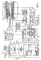
- FIG. 1 A system is shown and described to acquire MR images capable of infinitely variable field-of-view (FOV) adjustments.
- MRI magnetic resonance imaging
- FIG. 1 the major components of a preferred magnetic resonance imaging (MRI) system 10 incorporating the present invention are shown.
- the operation of the system is controlled from an operator console 12 which includes a keyboard or other input device 13, a control panel 14, and a display or screen 16.
- the console 12 communicates through a link 18 with a separate computer system 20 that enables an operator to control the production and display of images on the screen 16.
- the computer system 20 includes a number of modules which communicate with each other through a backplane 20a. These include an image processor module 22, a CPU module 24 and a memory module 26, known in the art as a frame buffer for storing image data arrays.
- the computer system 20 is linked to disk storage 28 and tape drive 30 for storage of image data and programs, and communicates with a separate system control 32 through a high speed serial link 34.
- the input device 13 can include a mouse, joystick, keyboard, track ball, touch activated screen, light wand, voice control, or any similar or equivalent input device, and may be used for interactive geometry prescription.
- the system control 32 includes a set of modules connected together by a backplane 32a. These include a CPU module 36 and a pulse generator module 38 which connects to the operator console 12 through a serial link 40. It is through link 40 that the system control 32 receives commands from the operator to indicate the scan sequence that is to be performed.
- the pulse generator module 38 operates the system components to carry out the desired scan sequence and produces data which indicates the timing, strength and shape of the RF pulses produced, and the timing and length of the data acquisition window.
- the pulse generator module 38 connects to a set of gradient amplifiers 42, to indicate the timing and shape of the gradient pulses that are produced during the scan.
- the pulse generator module 38 can also receive patient data from a physiological acquisition controller 44 that receives signals from a number of different sensors connected to the patient, such as ECG signals from electrodes attached to the patient. And finally, the pulse generator module 38 connects to a scan room interface circuit 46 which receives signals from various sensors associated with the condition of the patient and the magnet system. It is also through the scan room interface circuit 46 that a patient positioning system 48 receives commands to move the patient to the desired position for the scan.
- the gradient waveforms produced by the pulse generator module 38 are applied to the gradient amplifier system 42 having G x , G y , and G z amplifiers.
- Each gradient amplifier excites a corresponding physical gradient coil in a gradient coil assembly generally designated 50 to produce the magnetic field gradients used for spatially encoding acquired signals.
- the gradient coil assembly 50 forms part of a magnet assembly 52 which includes a polarizing magnet 54 and a whole-body RF coil 56.
- a transceiver module 58 in the system control 32 produces pulses which are amplified by an RF amplifier 60 and coupled to the RF coil 56 by a transmit/receive switch 62.
- the resulting signals emitted by the excited nuclei in the patient may be sensed by the same RF coil 56 and coupled through the transmit/receive switch 62 to a preamplifier 64.
- the amplified MR signals are demodulated, filtered, and digitized in the receiver section of the transceiver 58.
- the transmit/receive switch 62 is controlled by a signal from the pulse generator module 38 to electrically connect the RF amplifier 60 to the coil 56 during the transmit mode and to connect the preamplifier 64 to the coil 56 during the receive mode.
- the transmit/receive switch 62 can also enable a separate RF coil (for example, a surface coil) to be used in either the transmit or receive mode.
- the MR signals picked up by the RF coil 56 are digitized by the transceiver module 58 and transferred to a memory module 66 in the system control 32.
- a scan is complete when an array of raw k-space data has been acquired in the memory module 66.
- This raw k-space data is rearranged into separate k-space data arrays for each image to be reconstructed, and each of these is input to an array processor 68 which operates to Fourier transform the data into an array of image data.
- This image data is conveyed through the serial link 34 to the computer system 20 where it is stored in memory and/or other storage media, such as disk storage 28.
- this image data may be archived in long term storage, such as on the tape drive 30, or it may be further processed by the image processor 22 and conveyed to the operator console 12 and presented on the display 16.
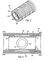
- Gradient coil assembly 100 includes a primary gradient coil 102 shown in phantom.
- Coil assembly 100 further includes a primary higher order gradient coil assembly 104.
- Coil assembly 104 includes a first half 104(a) and a second half 104(b).
- Positioned circumferentially about coil 104 is a secondary higher order gradient coil 106.
- Coil 106 operates as a shielding coil for the primary higher order gradient coil assembly 104. Shielding coil 106 assists in preventing eddy current from being induced in magnet 52 of Fig. 1 .
- Coil assembly 100 further includes a secondary gradient coil 108 disposed circumferentially about coil 106.
- Coil 108 functions as a shielding coil for the primary gradient coil 102 and likewise operates to prevent eddy current from being induced in the magnet.
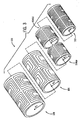
- Fig. 3 is an exploded view of coil assembly 100 of Fig. 2 which illustrates the concentric characteristics of coil assembly 100.
- Coil assembly 100 is designed such that primary gradient coil 102 has a radius R i wherein R i is less than R j , the radius of the primary higher order gradient coil 104. Likewise, R j is less than R k , the radius of secondary higher order gradient coil 106.
- Secondary gradient coil 108 has a radius R 1 that exceeds the radius of secondary shim coil 106.
- gradient coil assembly 100 is designed such that coil 102 is disposed interiorally of coil 104.
- coil 104 is designed to be positioned interiorally of coil 106 which is likewise designed to be positioned in an interior of coil 108.
- FIG. 4 a cross-sectional view of the coil assembly 100 is shown.
- Fig. 4 illustrates the concentric nature of coil assembly 100.
- coil 102 is disposed in the interior of coil 104 which is disposed in the interior of coil 106, which together are disposed in the interior of coil 108.
- FOV 112 is associated with gradient coil 102 and is smaller than FOV 114 which is associated with the entire coil assembly 100.
- Use of the higher order gradient coil 104 enables increasing the size of FOV 112 to FOV 114 incrementally, or with infinite variability.
- the operating modes include operating the gradient coil 102 alone or connecting coil 102 and coil 104 in series to provide a larger FOV, such as FOV 114. It should be noted that coil 102 and coil 104 may be jointly operated to create a smaller FOV than that generated by coil 102 alone. Additionally, coils 102 and 104 may be driven in parallel by separate power supplies to produce variable linearity within the FOV. As indicated previously, shielding coils such as coils 106 and 108 may be implemented to prevent eddy current from being induced in the magnet.
- the FOV may be varied by adjusting the current in coil 104.
- G x is the gradient strength as determined by the gradient coil and coefficients, a n , determine the linearity of the gradient or FOV.
- Equation 3 illustrates that by varying the sign and/or magnitude of b n , the linearity for the field of view of the total gradient field may be changed.
- the sign and magnitude of b n can be varied by changing the polarity and magnitude of the current to the higher order gradient coil, together or independently.
- modifying the current in the higher order gradient or shim coil increases or decreases the FOV. Therefore, it is evident that this "shim coil" satisfies the same type of requirements as a conventional gradient coil, unlike traditional shim coils used for magnetic field shimming. As is known, such requirements include low inductance and resistance with high efficiency ratings.
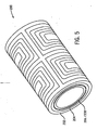
- coil assembly 200 includes a secondary gradient coil 202 operating as a shielding coil for a primary gradient coil 208.
- Coil assembly 200 further includes a secondary higher order gradient coil 204 operating as a shielding coil for a primary higher order gradient coil 206.
- primary gradient coil 208 and primary higher order gradient coil assembly 206 are placed on the same surface, therefore, there is no overlap between the two coils.
- Combined coil set 206 and 208 is then concentrically located with respect to coil 204 which is disposed in the interior of coil 202.
- coils 206 and 208 have the same radius whereas the radius of coil 204 is greater than the radii of coils 206 and 208 but less than the radius of coil 202.
- modulating the current in coil assembly 206 enables modification of the FOV in the same infinite manner within the physical bounds of the coils.
Claims (2)
- Système d'imagerie par résonance magnétique, IRM, comprenant :une bobine de gradient (102) disposée autour de l'entrefer d'un aimant, laquelle produit un champ magnétique polarisant ;un système d'émetteur-récepteur RF et un commutateur RF commandés par un module d'impulsions afin de transmettre des signaux RF à un ensemble de bobines RF dans le but d'acquérir des images de résonance magnétique d'un champ de vue, CDV ;un ensemble de bobine de gradient d'ordre supérieur (104) conçu pour régler le CDV et disposé de manière à chevaucher les extrémités de ladite bobine de gradient (102), ledit ensemble de bobine de gradient d'ordre supérieur (104) ayant un rayon plus grand que le rayon de ladite bobine de gradient (102) ; etune commande pour régler ledit CDV en modulant le courant dans l'ensemble de bobine de gradient d'ordre supérieur d'après une réception d'instructions ;dans lequel ladite bobine de gradient et ledit ensemble de bobine de gradient d'ordre supérieur (104) sont excités en parallèle par des sources d'électricité séparées afin de produire un CDV réglable ;ledit système d'IRM étant caractérisé par :une bobine écran (106) disposée à l'extérieur dudit ensemble de bobine de gradient d'ordre supérieur (104) et conçue pour arrêter les champs magnétiques à gradient générés par ledit ensemble de bobine de gradient d'ordre supérieur ; etune seconde bobine écran (108) disposée à l'extérieur de ladite bobine écran (106) et conçue pour arrêter les champs magnétiques générés par ladite bobine de gradient (102).
- Procédé de fabrication d'appareil d'imagerie par résonance magnétique, IRM, le procédé comprenant des étapes de :mise en place d'une bobine de gradient (102) autour de l'entrefer d'un aimant qui produit un champ magnétique polarisant ;fourniture d'un système d'émetteur-récepteur RF et d'un commutateur RF commandés par un module d'impulsions afin de transmettre des signaux RF à un ensemble de bobines RF dans le but d'acquérir des images de résonance magnétique d'un champ de vue, CDV ;mise en place d'un ensemble de bobine de gradient d'ordre supérieur (104) conçu pour régler le CDV, chevauchant les extrémités de ladite bobine de gradient (102), ledit ensemble de bobine de gradient d'ordre supérieur (104) ayant un rayon plus grand que le rayon de ladite bobine de gradient (102) ;fourniture de deux sources d'électricité séparées excitant en parallèle ladite bobine de gradient (102) et ledit ensemble de bobine de gradient d'ordre supérieur (104) ; etexécution d'une commande pour faire varier le CDV par incréments en modulant le courant dans ledit ensemble de bobine de gradient d'ordre supérieur (104) d'après une réception d'instructions afin de créer un CDV réglable ;le procédé étant caractérisé par :la mise en place d'une bobine écran (106) à l'extérieur dudit ensemble de bobine de gradient d'ordre supérieur (104), laquelle bobine écran (106) étant conçue pour arrêter les champs magnétiques à gradient générés par ledit ensemble de bobine de gradient d'ordre supérieur (104) ; etla mise en place d'une seconde bobine écran (108) à l'extérieur de ladite bobine écran (106), laquelle seconde bobine écran étant conçue pour arrêter les champs magnétiques à gradient générés par ladite bobine de gradient.
Applications Claiming Priority (2)
| Application Number | Priority Date | Filing Date | Title |
|---|---|---|---|
| US10/063,421 US6630829B1 (en) | 2002-04-22 | 2002-04-22 | Gradient coil set capable of producing a variable field of view |
| US63421 | 2002-04-22 |
Publications (2)
| Publication Number | Publication Date |
|---|---|
| EP1357391A1 EP1357391A1 (fr) | 2003-10-29 |
| EP1357391B1 true EP1357391B1 (fr) | 2010-03-03 |
Family
ID=28673461
Family Applications (1)
| Application Number | Title | Priority Date | Filing Date |
|---|---|---|---|
| EP03252473A Expired - Fee Related EP1357391B1 (fr) | 2002-04-22 | 2003-04-17 | Ensemble de bobines de gradient pouvant produire un champ de vision variable |
Country Status (4)
| Country | Link |
|---|---|
| US (1) | US6630829B1 (fr) |
| EP (1) | EP1357391B1 (fr) |
| JP (1) | JP4465158B2 (fr) |
| DE (1) | DE60331498D1 (fr) |
Families Citing this family (25)
| Publication number | Priority date | Publication date | Assignee | Title |
|---|---|---|---|---|
| JP4118722B2 (ja) * | 2003-03-24 | 2008-07-16 | ジーイー・メディカル・システムズ・グローバル・テクノロジー・カンパニー・エルエルシー | Rfコイル装置および磁気共鳴撮影装置 |
| US6975116B2 (en) * | 2003-11-26 | 2005-12-13 | Ge Medical Systems Global Technology Company, Llc | Method and apparatus for multiple field of view gradient coils |
| US7871465B2 (en) | 2004-05-28 | 2011-01-18 | Seiko Epson Corporation | Ink composition, and ink jet recording method and recorded matter using the same |
| JP4365275B2 (ja) * | 2004-06-28 | 2009-11-18 | 株式会社日立製作所 | 均一磁場発生装置 |
| US20070262776A1 (en) * | 2006-05-10 | 2007-11-15 | Petropoulos Labros S | Magnetic Resonance Imaging Magnet Assembly System with Improved Homogeneity |
| WO2008053451A1 (fr) * | 2006-11-03 | 2008-05-08 | Koninklijke Philips Electronics N.V. | Séparation de bobine de gradient pour un système irm |
| EP2096987A2 (fr) * | 2006-12-20 | 2009-09-09 | Philips Intellectual Property & Standards GmbH | Ispositif et procédé permettant d'influencer et/ou de détecter des particules magnétiques dans une zone d'action |
| US9995810B2 (en) | 2008-06-20 | 2018-06-12 | Weinberg Medical Physics Inc | Apparatus and method for decreasing bio-effects of magnetic gradient field gradients |
| US8466680B2 (en) * | 2008-06-20 | 2013-06-18 | Weinberg Medical Physics Llc | Apparatus and method for decreasing bio-effects of magnetic gradient field gradients |
| WO2011008969A1 (fr) | 2009-07-15 | 2011-01-20 | Viewray Incorporated | Procédé et appareil pour blinder un accélérateur linéaire et un dispositif d'imagerie par résonance magnétique l'un de l'autre |
| CA2780647C (fr) | 2009-11-20 | 2023-08-22 | Viewray Incorporated | Bobine de gradient autoblindee |
| CN104459584B (zh) * | 2009-12-02 | 2018-03-20 | 纳纳利塞斯公司 | 用于产生均匀磁场的方法和装置 |
| US8698497B2 (en) * | 2010-09-23 | 2014-04-15 | General Electric Company | Multi-field-of-view gradient coil |
| CN103327890B (zh) * | 2011-01-14 | 2016-07-06 | 株式会社日立医疗器械 | 倾斜磁场线圈装置以及磁共振成像装置 |
| US9533167B2 (en) | 2011-01-14 | 2017-01-03 | Massachusetts Institute Of Technology | System and method for manipulation of devices using magnetic fields |
| JP6246129B2 (ja) | 2011-11-16 | 2017-12-13 | コーニンクレッカ フィリップス エヌ ヴェKoninklijke Philips N.V. | 広視野を有する、磁性粒子に影響を及ぼし、且つ/又は磁性粒子を検出する装置及び方法 |
| US8981779B2 (en) | 2011-12-13 | 2015-03-17 | Viewray Incorporated | Active resistive shimming fro MRI devices |
| US9446263B2 (en) | 2013-03-15 | 2016-09-20 | Viewray Technologies, Inc. | Systems and methods for linear accelerator radiotherapy with magnetic resonance imaging |
| JP6971246B2 (ja) | 2015-11-06 | 2021-11-24 | シーダーズ−サイナイ メディカル センター | 次世代の磁気共鳴コイルのための統合されたコイル(unic)システム及び方法 |
| US10132883B2 (en) | 2016-05-31 | 2018-11-20 | General Electric Company | Foldable coil array |
| WO2018187217A1 (fr) | 2017-04-02 | 2018-10-11 | Imagion Biosystems Inc. | Procédés et appareils relatifs à des mesures de relaxométrie magnétique en présence d'une réponse environnementale à une excitation magnétique |
| EP3404435B1 (fr) | 2017-05-18 | 2022-08-31 | Siemens Healthcare GmbH | Unité de bobines à gradient pour appareil à résonance magnétique |
| WO2019112880A1 (fr) | 2017-12-06 | 2019-06-13 | Viewray Technologies, Inc. | Optimisation de la radiothérapie multimodale |
| US11209509B2 (en) | 2018-05-16 | 2021-12-28 | Viewray Technologies, Inc. | Resistive electromagnet systems and methods |
| WO2020198395A1 (fr) | 2019-03-25 | 2020-10-01 | Promaxo, Inc. | Bobines de champ-gradient d'irm rapide monoface et leurs applications |
Family Cites Families (25)
| Publication number | Priority date | Publication date | Assignee | Title |
|---|---|---|---|---|
| US4881034A (en) | 1988-01-19 | 1989-11-14 | The Regents Of The University Of California | Switchable MRI RF coil array with individual coils having different and overlapping fields of view |
| US5136273A (en) | 1988-10-17 | 1992-08-04 | Kabushiki Kaisha Toshiba | Magnet apparatus for use in a magnetic resonance imaging system |
| US5406205A (en) | 1989-11-08 | 1995-04-11 | Bruker Analytische Messtechnik Gmbh | Gradient-generation system, nuclear spin tomograph, and process for the generation of images with a nuclear-spin tomograph |
| US5311135A (en) | 1992-12-11 | 1994-05-10 | General Electric Company | Multiple tap gradient field coil for magnetic resonance imaging |
| DE69418404T2 (de) | 1993-09-16 | 1999-11-11 | Koninkl Philips Electronics Nv | Korrektur der Polarität des Auslesegradienten in Bilderzeugung durch EPI und GRASE magnetische Resonanz |
| GB2295020B (en) | 1994-11-03 | 1999-05-19 | Elscint Ltd | Modular whole - body gradient coil |
| US5760583A (en) | 1996-03-13 | 1998-06-02 | Ge Yokogawa Medical Systems, Limited | RF coil for MRI and MRI apparatus |
| DE19515586A1 (de) | 1995-04-27 | 1996-10-31 | Siemens Ag | Hochfrequenz-Antennensystem eines Gerätes zur magnetischen Kernresonanz |
| DE19616464A1 (de) | 1996-04-25 | 1997-11-06 | Philips Patentverwaltung | MR-Gerät mit einer Zylinderspulenanordnung und einer Oberflächenspulenanordnung |
| JP3670452B2 (ja) | 1996-07-31 | 2005-07-13 | 株式会社東芝 | 磁場発生用コイルユニットおよびコイル巻装方法 |
| US6137291A (en) | 1996-08-19 | 2000-10-24 | Oregon Health Sciences University | Telescoping coil array for magnetic resonance imaging of extremities |
| US5998999A (en) | 1996-12-12 | 1999-12-07 | Picker International, Inc. | Volume RF coils with integrated high resolution focus coils for magnetic resonance imaging |
| AU6182798A (en) | 1997-02-25 | 1998-09-09 | Advanced Imaging Research, Inc. | Radio-frequency coil array for resonance analysis |
| US6175237B1 (en) | 1997-03-05 | 2001-01-16 | Doty Scientific, Inc. | Center-fed paralleled coils for MRI |
| US5986454A (en) | 1997-03-21 | 1999-11-16 | Varian, Inc. | Quadrature elliptical birdcage coil for NMR |
| US5928148A (en) | 1997-06-02 | 1999-07-27 | Cornell Research Foundation, Inc. | Method for performing magnetic resonance angiography over a large field of view using table stepping |
| DE19732783C1 (de) | 1997-07-30 | 1999-03-04 | Bruker Medizintech | HF-Spulensystem für eine MR-Meßeinrichtung |
| US6384601B1 (en) * | 1998-04-06 | 2002-05-07 | The United States Of America As Represented By The Secretary Of Department Of Health & Human Services | Local magnetization spoiling using a gradient insert for reducing the field of view in magnetic resonance imaging |
| US6223065B1 (en) | 1998-04-15 | 2001-04-24 | Medrad, Inc. | Automatic coil element selection in large MRI coil arrays |
| JP3051374B2 (ja) | 1998-07-21 | 2000-06-12 | ジーイー横河メディカルシステム株式会社 | 磁気共鳴撮像装置 |
| JP2002528148A (ja) | 1998-10-20 | 2002-09-03 | コーニンクレッカ フィリップス エレクトロニクス エヌ ヴィ | 補正コイルを有する傾斜コイル系を含む磁気共鳴撮像装置 |
| DE19851583C2 (de) | 1998-11-09 | 2002-10-10 | Siemens Ag | Verfahren zum Betrieb eines MR-Tomographiegeräts mit umschaltbaren Feldqualitäten und MR-Tomographiegerät |
| DE19851584C1 (de) * | 1998-11-09 | 2000-04-20 | Siemens Ag | Schaltbare Gradientenspulenanordnung |
| DE19955117C2 (de) | 1999-11-16 | 2001-09-27 | Siemens Ag | Verfahren zum Betrieb eines Magnetresonanztomographiegeräts |
| US6294972B1 (en) | 2000-08-03 | 2001-09-25 | The Mcw Research Foundation, Inc. | Method for shimming a static magnetic field in a local MRI coil |
-
2002
- 2002-04-22 US US10/063,421 patent/US6630829B1/en not_active Expired - Lifetime
-
2003
- 2003-04-17 DE DE60331498T patent/DE60331498D1/de not_active Expired - Lifetime
- 2003-04-17 EP EP03252473A patent/EP1357391B1/fr not_active Expired - Fee Related
- 2003-04-21 JP JP2003115177A patent/JP4465158B2/ja not_active Expired - Lifetime
Also Published As
| Publication number | Publication date |
|---|---|
| EP1357391A1 (fr) | 2003-10-29 |
| US20030197507A1 (en) | 2003-10-23 |
| US6630829B1 (en) | 2003-10-07 |
| DE60331498D1 (de) | 2010-04-15 |
| JP4465158B2 (ja) | 2010-05-19 |
| JP2003339668A (ja) | 2003-12-02 |
Similar Documents
| Publication | Publication Date | Title |
|---|---|---|
| EP1357391B1 (fr) | Ensemble de bobines de gradient pouvant produire un champ de vision variable | |
| US8415950B2 (en) | System and method for parallel transmission in MR imaging | |
| US6479999B1 (en) | Efficiently shielded MRI gradient coil with discretely or continuously variable field of view | |
| US6198282B1 (en) | Optimized MRI gradient system for providing minimum-duration gradient pulses | |
| US7221161B2 (en) | Coil arrays for parallel imaging in magnetic resonance imaging | |
| US7855559B2 (en) | Circuit and apparatus for decoupling RF surface coils | |
| US6590392B2 (en) | Switchable FOV coil assembly having end saddle coils | |
| US6538441B1 (en) | RF coil for reduced electric field exposure for use in very high field magnetic resonance imaging | |
| US6563315B1 (en) | Gradient coil apparatus and method of micro-imaging | |
| US7570141B2 (en) | Method of designing a shim coil to reduce field settling time | |
| US6487436B1 (en) | Switchable field of view apparatus and method for magnetic resonance imaging | |
| EP1333295A2 (fr) | Séquence d'impulsions de saturation pour la suppression individuelle des artéfacts dans des images RMN | |
| US6822451B2 (en) | Non-coupling magnetic sheilding coil | |
| US20140184226A1 (en) | System and apparatus for active high order shimming | |
| US8766635B2 (en) | System and apparatus for balancing radial forces in a gradient coil | |
| EP1411367B1 (fr) | Bobine à gradient pour l'imagerie par résonance magnétique | |
| US8143893B2 (en) | Thin extended-cavity RF coil for MRI | |
| US6538442B2 (en) | MRI system having RF shielding gradient coil structure | |
| US6466017B1 (en) | MRI system with modular gradient system | |
| US20070038068A1 (en) | Mr imaging method | |
| US20060132133A1 (en) | Method and system for spatial-spectral excitation by parallel RF transmission | |
| US7019525B2 (en) | Method and apparatus for magnetic resonance imaging |
Legal Events
| Date | Code | Title | Description |
|---|---|---|---|
| PUAI | Public reference made under article 153(3) epc to a published international application that has entered the european phase |
Free format text: ORIGINAL CODE: 0009012 |
|
| AK | Designated contracting states |
Kind code of ref document: A1 Designated state(s): AT BE BG CH CY CZ DE DK EE ES FI FR GB GR HU IE IT LI LU MC NL PT RO SE SI SK TR |
|
| AX | Request for extension of the european patent |
Extension state: AL LT LV MK |
|
| 17P | Request for examination filed |
Effective date: 20040429 |
|
| AKX | Designation fees paid |
Designated state(s): DE NL |
|
| 17Q | First examination report despatched |
Effective date: 20070516 |
|
| GRAP | Despatch of communication of intention to grant a patent |
Free format text: ORIGINAL CODE: EPIDOSNIGR1 |
|
| GRAS | Grant fee paid |
Free format text: ORIGINAL CODE: EPIDOSNIGR3 |
|
| GRAA | (expected) grant |
Free format text: ORIGINAL CODE: 0009210 |
|
| AK | Designated contracting states |
Kind code of ref document: B1 Designated state(s): DE NL |
|
| REG | Reference to a national code |
Ref country code: NL Ref legal event code: T3 |
|
| REF | Corresponds to: |
Ref document number: 60331498 Country of ref document: DE Date of ref document: 20100415 Kind code of ref document: P |
|
| PLBE | No opposition filed within time limit |
Free format text: ORIGINAL CODE: 0009261 |
|
| STAA | Information on the status of an ep patent application or granted ep patent |
Free format text: STATUS: NO OPPOSITION FILED WITHIN TIME LIMIT |
|
| 26N | No opposition filed |
Effective date: 20101206 |
|
| PGFP | Annual fee paid to national office [announced via postgrant information from national office to epo] |
Ref country code: DE Payment date: 20130429 Year of fee payment: 11 |
|
| PGFP | Annual fee paid to national office [announced via postgrant information from national office to epo] |
Ref country code: NL Payment date: 20130426 Year of fee payment: 11 |
|
| REG | Reference to a national code |
Ref country code: DE Ref legal event code: R119 Ref document number: 60331498 Country of ref document: DE |
|
| REG | Reference to a national code |
Ref country code: NL Ref legal event code: V1 Effective date: 20141101 |
|
| REG | Reference to a national code |
Ref country code: DE Ref legal event code: R119 Ref document number: 60331498 Country of ref document: DE Effective date: 20141101 |
|
| PG25 | Lapsed in a contracting state [announced via postgrant information from national office to epo] |
Ref country code: DE Free format text: LAPSE BECAUSE OF NON-PAYMENT OF DUE FEES Effective date: 20141101 |
|
| PG25 | Lapsed in a contracting state [announced via postgrant information from national office to epo] |
Ref country code: NL Free format text: LAPSE BECAUSE OF NON-PAYMENT OF DUE FEES Effective date: 20141101 |