EP1357013A1 - Système et méthode pour utiliser l'intention de l'operateur d'un véhicule pour régler la réponse du système de contrôle du véhicule - Google Patents
Système et méthode pour utiliser l'intention de l'operateur d'un véhicule pour régler la réponse du système de contrôle du véhicule Download PDFInfo
- Publication number
- EP1357013A1 EP1357013A1 EP03075859A EP03075859A EP1357013A1 EP 1357013 A1 EP1357013 A1 EP 1357013A1 EP 03075859 A EP03075859 A EP 03075859A EP 03075859 A EP03075859 A EP 03075859A EP 1357013 A1 EP1357013 A1 EP 1357013A1
- Authority
- EP
- European Patent Office
- Prior art keywords
- vehicle
- control system
- intent
- sensor
- wheel
- Prior art date
- Legal status (The legal status is an assumption and is not a legal conclusion. Google has not performed a legal analysis and makes no representation as to the accuracy of the status listed.)
- Granted
Links
- 238000000034 method Methods 0.000 title claims abstract description 19
- 230000004044 response Effects 0.000 title claims abstract description 19
- 238000004590 computer program Methods 0.000 claims abstract description 13
- 230000000644 propagated effect Effects 0.000 claims description 4
- 230000003287 optical effect Effects 0.000 claims 7
- 238000004519 manufacturing process Methods 0.000 claims 1
- 230000008859 change Effects 0.000 description 21
- 230000001133 acceleration Effects 0.000 description 10
- 230000008569 process Effects 0.000 description 2
- 230000005540 biological transmission Effects 0.000 description 1
- 238000004891 communication Methods 0.000 description 1
- 238000012937 correction Methods 0.000 description 1
- 238000001514 detection method Methods 0.000 description 1
- 230000026058 directional locomotion Effects 0.000 description 1
- 238000009429 electrical wiring Methods 0.000 description 1
- 230000005670 electromagnetic radiation Effects 0.000 description 1
- 238000005516 engineering process Methods 0.000 description 1
- 230000002708 enhancing effect Effects 0.000 description 1
- 239000000835 fiber Substances 0.000 description 1
- 230000033001 locomotion Effects 0.000 description 1
- 239000000463 material Substances 0.000 description 1
- 238000012986 modification Methods 0.000 description 1
- 230000004048 modification Effects 0.000 description 1
- 238000012544 monitoring process Methods 0.000 description 1
- 230000009467 reduction Effects 0.000 description 1
- 230000003068 static effect Effects 0.000 description 1
- 230000001052 transient effect Effects 0.000 description 1
- 230000000007 visual effect Effects 0.000 description 1
Images


Classifications
-
- B—PERFORMING OPERATIONS; TRANSPORTING
- B60—VEHICLES IN GENERAL
- B60W—CONJOINT CONTROL OF VEHICLE SUB-UNITS OF DIFFERENT TYPE OR DIFFERENT FUNCTION; CONTROL SYSTEMS SPECIALLY ADAPTED FOR HYBRID VEHICLES; ROAD VEHICLE DRIVE CONTROL SYSTEMS FOR PURPOSES NOT RELATED TO THE CONTROL OF A PARTICULAR SUB-UNIT
- B60W10/00—Conjoint control of vehicle sub-units of different type or different function
- B60W10/20—Conjoint control of vehicle sub-units of different type or different function including control of steering systems
-
- B—PERFORMING OPERATIONS; TRANSPORTING
- B60—VEHICLES IN GENERAL
- B60K—ARRANGEMENT OR MOUNTING OF PROPULSION UNITS OR OF TRANSMISSIONS IN VEHICLES; ARRANGEMENT OR MOUNTING OF PLURAL DIVERSE PRIME-MOVERS IN VEHICLES; AUXILIARY DRIVES FOR VEHICLES; INSTRUMENTATION OR DASHBOARDS FOR VEHICLES; ARRANGEMENTS IN CONNECTION WITH COOLING, AIR INTAKE, GAS EXHAUST OR FUEL SUPPLY OF PROPULSION UNITS IN VEHICLES
- B60K28/00—Safety devices for propulsion-unit control, specially adapted for, or arranged in, vehicles, e.g. preventing fuel supply or ignition in the event of potentially dangerous conditions
- B60K28/10—Safety devices for propulsion-unit control, specially adapted for, or arranged in, vehicles, e.g. preventing fuel supply or ignition in the event of potentially dangerous conditions responsive to conditions relating to the vehicle
- B60K28/16—Safety devices for propulsion-unit control, specially adapted for, or arranged in, vehicles, e.g. preventing fuel supply or ignition in the event of potentially dangerous conditions responsive to conditions relating to the vehicle responsive to, or preventing, skidding of wheels
-
- B—PERFORMING OPERATIONS; TRANSPORTING
- B60—VEHICLES IN GENERAL
- B60W—CONJOINT CONTROL OF VEHICLE SUB-UNITS OF DIFFERENT TYPE OR DIFFERENT FUNCTION; CONTROL SYSTEMS SPECIALLY ADAPTED FOR HYBRID VEHICLES; ROAD VEHICLE DRIVE CONTROL SYSTEMS FOR PURPOSES NOT RELATED TO THE CONTROL OF A PARTICULAR SUB-UNIT
- B60W10/00—Conjoint control of vehicle sub-units of different type or different function
- B60W10/04—Conjoint control of vehicle sub-units of different type or different function including control of propulsion units
- B60W10/06—Conjoint control of vehicle sub-units of different type or different function including control of propulsion units including control of combustion engines
-
- B—PERFORMING OPERATIONS; TRANSPORTING
- B60—VEHICLES IN GENERAL
- B60W—CONJOINT CONTROL OF VEHICLE SUB-UNITS OF DIFFERENT TYPE OR DIFFERENT FUNCTION; CONTROL SYSTEMS SPECIALLY ADAPTED FOR HYBRID VEHICLES; ROAD VEHICLE DRIVE CONTROL SYSTEMS FOR PURPOSES NOT RELATED TO THE CONTROL OF A PARTICULAR SUB-UNIT
- B60W10/00—Conjoint control of vehicle sub-units of different type or different function
- B60W10/18—Conjoint control of vehicle sub-units of different type or different function including control of braking systems
-
- B—PERFORMING OPERATIONS; TRANSPORTING
- B60—VEHICLES IN GENERAL
- B60W—CONJOINT CONTROL OF VEHICLE SUB-UNITS OF DIFFERENT TYPE OR DIFFERENT FUNCTION; CONTROL SYSTEMS SPECIALLY ADAPTED FOR HYBRID VEHICLES; ROAD VEHICLE DRIVE CONTROL SYSTEMS FOR PURPOSES NOT RELATED TO THE CONTROL OF A PARTICULAR SUB-UNIT
- B60W30/00—Purposes of road vehicle drive control systems not related to the control of a particular sub-unit, e.g. of systems using conjoint control of vehicle sub-units
- B60W30/18—Propelling the vehicle
-
- B—PERFORMING OPERATIONS; TRANSPORTING
- B62—LAND VEHICLES FOR TRAVELLING OTHERWISE THAN ON RAILS
- B62D—MOTOR VEHICLES; TRAILERS
- B62D7/00—Steering linkage; Stub axles or their mountings
- B62D7/06—Steering linkage; Stub axles or their mountings for individually-pivoted wheels, e.g. on king-pins
- B62D7/14—Steering linkage; Stub axles or their mountings for individually-pivoted wheels, e.g. on king-pins the pivotal axes being situated in more than one plane transverse to the longitudinal centre line of the vehicle, e.g. all-wheel steering
- B62D7/15—Steering linkage; Stub axles or their mountings for individually-pivoted wheels, e.g. on king-pins the pivotal axes being situated in more than one plane transverse to the longitudinal centre line of the vehicle, e.g. all-wheel steering characterised by means varying the ratio between the steering angles of the steered wheels
- B62D7/159—Steering linkage; Stub axles or their mountings for individually-pivoted wheels, e.g. on king-pins the pivotal axes being situated in more than one plane transverse to the longitudinal centre line of the vehicle, e.g. all-wheel steering characterised by means varying the ratio between the steering angles of the steered wheels characterised by computing methods or stabilisation processes or systems, e.g. responding to yaw rate, lateral wind, load, road condition
-
- B—PERFORMING OPERATIONS; TRANSPORTING
- B60—VEHICLES IN GENERAL
- B60T—VEHICLE BRAKE CONTROL SYSTEMS OR PARTS THEREOF; BRAKE CONTROL SYSTEMS OR PARTS THEREOF, IN GENERAL; ARRANGEMENT OF BRAKING ELEMENTS ON VEHICLES IN GENERAL; PORTABLE DEVICES FOR PREVENTING UNWANTED MOVEMENT OF VEHICLES; VEHICLE MODIFICATIONS TO FACILITATE COOLING OF BRAKES
- B60T2220/00—Monitoring, detecting driver behaviour; Signalling thereof; Counteracting thereof
- B60T2220/02—Driver type; Driving style; Driver adaptive features
-
- B—PERFORMING OPERATIONS; TRANSPORTING
- B60—VEHICLES IN GENERAL
- B60T—VEHICLE BRAKE CONTROL SYSTEMS OR PARTS THEREOF; BRAKE CONTROL SYSTEMS OR PARTS THEREOF, IN GENERAL; ARRANGEMENT OF BRAKING ELEMENTS ON VEHICLES IN GENERAL; PORTABLE DEVICES FOR PREVENTING UNWANTED MOVEMENT OF VEHICLES; VEHICLE MODIFICATIONS TO FACILITATE COOLING OF BRAKES
- B60T2260/00—Interaction of vehicle brake system with other systems
- B60T2260/02—Active Steering, Steer-by-Wire
- B60T2260/022—Rear-wheel steering; Four-wheel steering
-
- B—PERFORMING OPERATIONS; TRANSPORTING
- B60—VEHICLES IN GENERAL
- B60W—CONJOINT CONTROL OF VEHICLE SUB-UNITS OF DIFFERENT TYPE OR DIFFERENT FUNCTION; CONTROL SYSTEMS SPECIALLY ADAPTED FOR HYBRID VEHICLES; ROAD VEHICLE DRIVE CONTROL SYSTEMS FOR PURPOSES NOT RELATED TO THE CONTROL OF A PARTICULAR SUB-UNIT
- B60W50/00—Details of control systems for road vehicle drive control not related to the control of a particular sub-unit, e.g. process diagnostic or vehicle driver interfaces
- B60W2050/0001—Details of the control system
- B60W2050/0019—Control system elements or transfer functions
- B60W2050/0022—Gains, weighting coefficients or weighting functions
-
- B—PERFORMING OPERATIONS; TRANSPORTING
- B60—VEHICLES IN GENERAL
- B60W—CONJOINT CONTROL OF VEHICLE SUB-UNITS OF DIFFERENT TYPE OR DIFFERENT FUNCTION; CONTROL SYSTEMS SPECIALLY ADAPTED FOR HYBRID VEHICLES; ROAD VEHICLE DRIVE CONTROL SYSTEMS FOR PURPOSES NOT RELATED TO THE CONTROL OF A PARTICULAR SUB-UNIT
- B60W50/00—Details of control systems for road vehicle drive control not related to the control of a particular sub-unit, e.g. process diagnostic or vehicle driver interfaces
- B60W2050/0001—Details of the control system
- B60W2050/0019—Control system elements or transfer functions
- B60W2050/0028—Mathematical models, e.g. for simulation
- B60W2050/0031—Mathematical model of the vehicle
-
- B—PERFORMING OPERATIONS; TRANSPORTING
- B60—VEHICLES IN GENERAL
- B60W—CONJOINT CONTROL OF VEHICLE SUB-UNITS OF DIFFERENT TYPE OR DIFFERENT FUNCTION; CONTROL SYSTEMS SPECIALLY ADAPTED FOR HYBRID VEHICLES; ROAD VEHICLE DRIVE CONTROL SYSTEMS FOR PURPOSES NOT RELATED TO THE CONTROL OF A PARTICULAR SUB-UNIT
- B60W50/00—Details of control systems for road vehicle drive control not related to the control of a particular sub-unit, e.g. process diagnostic or vehicle driver interfaces
- B60W2050/0001—Details of the control system
- B60W2050/0043—Signal treatments, identification of variables or parameters, parameter estimation or state estimation
- B60W2050/0052—Filtering, filters
-
- B—PERFORMING OPERATIONS; TRANSPORTING
- B60—VEHICLES IN GENERAL
- B60W—CONJOINT CONTROL OF VEHICLE SUB-UNITS OF DIFFERENT TYPE OR DIFFERENT FUNCTION; CONTROL SYSTEMS SPECIALLY ADAPTED FOR HYBRID VEHICLES; ROAD VEHICLE DRIVE CONTROL SYSTEMS FOR PURPOSES NOT RELATED TO THE CONTROL OF A PARTICULAR SUB-UNIT
- B60W50/00—Details of control systems for road vehicle drive control not related to the control of a particular sub-unit, e.g. process diagnostic or vehicle driver interfaces
- B60W2050/0062—Adapting control system settings
- B60W2050/0075—Automatic parameter input, automatic initialising or calibrating means
-
- B—PERFORMING OPERATIONS; TRANSPORTING
- B60—VEHICLES IN GENERAL
- B60W—CONJOINT CONTROL OF VEHICLE SUB-UNITS OF DIFFERENT TYPE OR DIFFERENT FUNCTION; CONTROL SYSTEMS SPECIALLY ADAPTED FOR HYBRID VEHICLES; ROAD VEHICLE DRIVE CONTROL SYSTEMS FOR PURPOSES NOT RELATED TO THE CONTROL OF A PARTICULAR SUB-UNIT
- B60W2520/00—Input parameters relating to overall vehicle dynamics
- B60W2520/14—Yaw
-
- B—PERFORMING OPERATIONS; TRANSPORTING
- B60—VEHICLES IN GENERAL
- B60W—CONJOINT CONTROL OF VEHICLE SUB-UNITS OF DIFFERENT TYPE OR DIFFERENT FUNCTION; CONTROL SYSTEMS SPECIALLY ADAPTED FOR HYBRID VEHICLES; ROAD VEHICLE DRIVE CONTROL SYSTEMS FOR PURPOSES NOT RELATED TO THE CONTROL OF A PARTICULAR SUB-UNIT
- B60W2540/00—Input parameters relating to occupants
- B60W2540/18—Steering angle
-
- B—PERFORMING OPERATIONS; TRANSPORTING
- B60—VEHICLES IN GENERAL
- B60W—CONJOINT CONTROL OF VEHICLE SUB-UNITS OF DIFFERENT TYPE OR DIFFERENT FUNCTION; CONTROL SYSTEMS SPECIALLY ADAPTED FOR HYBRID VEHICLES; ROAD VEHICLE DRIVE CONTROL SYSTEMS FOR PURPOSES NOT RELATED TO THE CONTROL OF A PARTICULAR SUB-UNIT
- B60W2540/00—Input parameters relating to occupants
- B60W2540/30—Driving style
-
- Y—GENERAL TAGGING OF NEW TECHNOLOGICAL DEVELOPMENTS; GENERAL TAGGING OF CROSS-SECTIONAL TECHNOLOGIES SPANNING OVER SEVERAL SECTIONS OF THE IPC; TECHNICAL SUBJECTS COVERED BY FORMER USPC CROSS-REFERENCE ART COLLECTIONS [XRACs] AND DIGESTS
- Y02—TECHNOLOGIES OR APPLICATIONS FOR MITIGATION OR ADAPTATION AGAINST CLIMATE CHANGE
- Y02T—CLIMATE CHANGE MITIGATION TECHNOLOGIES RELATED TO TRANSPORTATION
- Y02T10/00—Road transport of goods or passengers
- Y02T10/10—Internal combustion engine [ICE] based vehicles
- Y02T10/40—Engine management systems
Definitions
- TCS traction control system
- SCS stability control
- Another type of vehicle control system four-wheel steering, enhances the stability of a vehicle at highway speeds by turning the rear-wheels in phase with the front-wheels, thus allowing for improved lane changing while reducing the,necessity to change the heading of the vehicle.
- four-wheel steering systems reduce the turning radius of a vehicle by turning the rear-wheels out-of-phase relative to the front-wheels.
- vehicle control systems While the goal of a vehicle control system is to anticipate a vehicle operator's intent and respond accordingly, vehicle control systems generally base their response on vehicle operator actions, such as the angling of the handwheel or the depression of the accelerator pedal, which are measured by sensors associated with the vehicle. For example, for a four-wheel steering system, the angling of a vehicle handwheel at high speeds may cause an estimation that the vehicle operator's intent is to translate a lane change. Similarly, the angling of a vehicle handwheel at low speeds may cause an estimation that the vehicle operator's intent is to change the vehicle's heading.
- a disadvantage of such methodologies is they do not account for circumstances where a vehicle operator's true intent may vary from the vehicle control system's estimate. For example, a vehicle operator's true intent may be to translate a lane at lower speeds or to turn the vehicle's heading at higher speeds. Therefore what is desired is a system and method for using vehicle operator intent to adjust a vehicle control system.
- a system and method for using vehicle operator intent to adjust a vehicle control system comprising: at least one vehicle control system associated with a vehicle, the control system being enabled to execute computer programs, the control system being enabled to receive data signals; at least one sensor for sensing vehicle operator intent, the sensor being enabled for transmitting data signals to the control system; and a computer program for developing a response command in relation to a representation of vehicle operator intent, the representation further comprising received data signals.
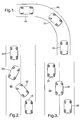
- Fig. 1 shows a vehicle without a rear-wheel steering system changing its heading while traveling along a curved road 16 from a first position 10 to a second position 12 to a third position 14.
- the vehicle operator must rotate the vehicle's handwheel sufficiently to cause the vehicle's heading to correspond to the curvature of the road 16 resulting in the generation of yaw and a corresponding lateral acceleration.
- Fig. 2 shows a vehicle without a rear-wheel steering system changing from one lane to another lane while traveling in the same direction.
- the vehicle operator In order to change lanes, the vehicle operator must make a series of handwheel adjustments. Initially, the vehicle 18 is traveling in the right lane of the road 20. The vehicle operator rotates the handwheel counter-clockwise causing the vehicle 22 to move from the right lane to the left lane. Once the vehicle 24 is traveling in the left lane, the vehicle operator rotates the handwheel clockwise to counteract excessive yaw caused by the vehicle operator's previous counter clockwise rotation of the handwheel. Finally, the vehicle operator rotates the handwheel counter-clockwise to cause the vehicle 26 to travel in a direction parallel to the road 20. It is understood that Fig.
- a vehicle lane change may be achieved using an alternative series of handwheel movements.
- a lane change could be achieved by angling the handwheel counter-clockwise, followed by straightening the handwheel, followed by angling the handwheel clockwise, followed by straightening the handwheel.
- Vehicles equipped with rear-wheel steering systems are capable of changing lanes with little or no change to vehicle heading and require a vehicle operator to make fewer handwheel adjustments. Moreover, when such a vehicle makes a purely translational lane change, there is little or no generation of yaw and thus the vehicle is better enabled to maximize traction and stability.
- the vehicle 28 is initially traveling in the right lane of the road 30. The vehicle operator rotates the handwheel counter-clockwise causing the vehicle 32 to move from the right lane to the left lane. Once the vehicle 34 is traveling in the left lane, the vehicle operator rotates the handwheel clockwise to maintain the vehicle's 34 direction of travel.
- a rear-wheel steering control system employing separate closed-loop feedback controller and open-loop feedforward control paths is disclosed in United States Patent No. 4,842,089 and is assigned to the assignee of the present application.
- the closed-loop feedback path may be optimized to enhance directional stability, to compensate for changes in vehicle or road condition, and to shape the steady-state response of the system.
- the separate open-loop feedforward control path may be optimized to shape both the transient and the steady-state response of the system.
- While an embodiment describes the use of vehicle operator intent to adjust a rear-wheel steering system wherein open-loop feedforward and closed-loop feedback are employed, it is understood that the present disclosure may be used in a vehicle with a plurality of vehicle control systems. Moreover, it is also understood that any vehicle control system known to one of ordinary skill in the art may be used including vehicle control systems that do not employ either open-loop feedforward or closed-loop feedback commands. In addition, while an embodiment describes the use of a single sensor device for determining driver intent, it is understood that a plurality of sensor devices may be used for determining driver intent without exceeding the scope of this disclosure.
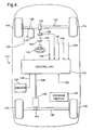
- Reference numeral 110 generally designates a motor vehicle having four steerable wheels.
- the front-wheels 112, 114 are steered together in response to rotation of an operator manipulated handwheel 116.
- the handwheel 116 is mechanically connected via steering column 118 to a pinion gear 120 which is maintained in meshing engagement with teeth formed on a front rack 122.
- the front rack 122 is connected to front-wheel tie rods (not shown), completing the mechanical linkage connecting the front-wheels 112, 114 to the handwheel 116.
- An electric motor 124 drives a second pinion gear 126, also maintained in meshing engagement with the front rack teeth.
- the motor 124 is adapted to be energized in relation to the operator exerted steering torque for generating a power steering assist torque which aids the vehicle operator exerted torque.
- a torque sensor 128 is disposed in relation to the steering column 118 for generating an electrical signal in accordance with the operator exerted steering torque. Such signal is applied as an input to a computer-based control unit 130, which among other things, controls the energization of electric motor 124 via line 132 for generating the proper magnitude and direction of steering assist.
- a signal indicative of the vehicle speed V x is applied as an input to the control unit 130 via line 134, which signal may also be used as a parameter for steering control.
- a signal indicative of the vehicle operator intent I d is applied as an input to the control unit 130 via line 135, which signal may also be used as a parameter for steering control.
- a plurality of sensors 137 are disposed in relation to the control unit 130 for generating an electrical signal in accordance with the vehicle operator's intent.
- the control unit 130 also controls the energization of an electric motor 136 as indicated by the line 138 to control the steering of rear-wheels 140, 142.
- the motor 136 rotatably drives a pinion gear 144 which is maintained in meshing engagement with teeth formed on a rear rack 146.
- the rack 146 is mechanically connected to the rear-wheel tie rods (not shown) so that the rear-wheels 140, 142 steer together.
- electrical signals indicative of the lateral and yaw velocities V y , and the front steering angle D f are supplied as inputs to the control unit 130 via lines 148-152.
- the lateral and yaw velocity inputs are obtained with accelerometers (not shown), and the front steering angle D f is obtained with rotary potentiometer 154 responsive to the rotary position of handwheel 116.
- the computer based control unit 130 performs the functions of a front steering angle filter, a reference model map, an open-loop controller, a closed-loop controller, and a summing junction.
- a computer program for performing said functions is located in a storage medium 156.
- the storage medium 156 may be separate from the control unit 130 or an integrated component of the control unit 130.
- the control unit 130 is enabled to receive said program code via a propagated data signal 158.
- the control unit 130 may implement one or more vehicle control systems such as an anti-lock braking system, traction control system, stability control system, front-wheel steering system, rear-wheel steering system, or four-wheel steering system.
- a vehicle control system In order to determine a vehicle operator's intent, a vehicle control system must be enabled to receive a representation of the intent.
- the intent is determined from data signals received by the control unit 130.
- the data signals are received from a plurality of sensors 137.
- the plurality of sensors 137 comprise any combination of sensors and sensor types known to one of ordinary skill in the art.
- a vehicle is equipped with a combination of vehicle operator intent sensors for purposes including enhancing the accuracy of the representation of the vehicle operator's intent. By way of example and for purposes of explanation, several types of sensors are discussed.
- the sensors include a visual detection device that is enabled to indicate the path of the road immediately ahead of the vehicle. Where road curvature or intersections are indicated, data signals represent the vehicle operator's intent to be to turn the vehicle. Where the road does not curve or intersect a second road, data signals represent the vehicle operator's intent to be to translate a lane change.
- the sensors include a global positioning satellite (“GPS") device.
- GPS global positioning satellite
- data signals represent the vehicle operator's intent to be to turn the vehicle.
- data signals represent the vehicle operator's intent to be to translate a lane change.
- the sensors include a vehicle hand-wheel velocity meter. Where a vehicle operator causes quick, large changes in hand-wheel angle, data signals represent the vehicle operator's intent to be to be to turn the vehicle. Where a vehicle operator causes slow, small changes in hand-wheel angle, data signals represent the vehicle operator's intent to be to translate a lane change.
- the sensors include a first device that is in communication with a second device wherein said second device is not located in said vehicle.
- the second device may be mobile, such as a device located in an adjacent vehicle, or fixed, such as a device located in a roadside railing or post.
- the second device provides information concerning roadway conditions such as the presence of curves, speed limits, etc. which can then be used to interpret operator's intent when combined with other signals (e.g., handwheel velocity, vehicle speed, etc.).
- the sensors include a vehicle operator actuated switch.
- the vehicle operator directly relays intent to the control system.
- a vehicle is equipped with a vehicle operator actuated switch, such as a turn signal, a GPS device, and a vehicle speed sensor. Where a street having a low speed limit is located parallel to and so close to a highway having a high speed limit that GPS indicators alone is insufficient for concluding on which road the vehicle is traveling, low vehicle speed coupled with turn signal actuation would cause the representation of the vehicle operator's intent to be to turn the vehicle.
- the vehicle control system generates a command to be carried out by the vehicle that is responsive to vehicle operator actions, such as the depression of an accelerator pedal or the angling of the vehicle handwheel and driver intent.
- vehicle operator actions such as the depression of an accelerator pedal or the angling of the vehicle handwheel and driver intent.
- the computer based control unit sends a response command Dr(CMD) to the vehicle's rear-wheel actuators.
- the response command Dr(CMD) is at least in part a function of vehicle operator intent.
- the flow chart of figures 5 and 6 represent a computer program executed by the computer based control unit in carrying out the vehicle control system's response.
- the initialization block 210 represents a series of instructions executed at the initialization of each period of vehicle operation for initializing the various registers, input counters and flags used in connection with the control of this invention. Thereafter, the instruction blocks 212-224 are repeatedly and sequentially executed as indicated by the flow lines and the return line 226.
- control unit is initialized 210.
- the control unit receives the various input signals at 212 including those for longitudinal velocity V x , vehicle operator intent I d , actual lateral or slip velocity V y , actual yaw velocity r, and front-wheel steering angle D f .
- such signals are supplied to the control unit 130 via lines 134, 135, 148, 150, and 152, respectively.
- the instruction block 214 pertains to the open-loop feedforward function designated by the control unit 130 in Fig. 4.
- the performance of such function comprises the steps of determining the open-loop gain ratio OLGR as a function of the longitudinal velocity V x , and computing the open-loop feedforward command Dr(OL) as a function of the measured front-wheel steering angle D f and OLGR.
- OLGR f( V x )
- Dr(OL) f (D f , OLGR)
- the instruction block 216 pertains to the front-wheel steering angle filter function designated by the filter implemented by control unit 130 in Fig.4.
- the filtered front-wheel steering angle D f ' is desired for noise rejection in the closed-loop feedback control path.
- the instructions designated by block 210 initially set the filtered front-wheel steering value D f ' to zero.
- Coefficients F1 and F2 are determined, the gain factor GF is computed, and the filtered output D f ' is updated according to the product of the steering angle change and the computed gain factor GF.
- F1 f (V x )
- F2 f (V x )
- GF F1 +
- D f ' D f ' + (D f - D f ')GF
- the instruction block 218 pertains to reference model function designated by the reference model map provided by control unit 130 in Fig. 4.
- the reference model map defines a desired vehicle response in terms of the desired yaw velocity r(des) and desired lateral or slip velocity V y (des).
- the reference model map is based on a cornering model of the vehicle and generates a static or steady-state reference point ( r(des), V y (des) ) for the closed-loop controller to follow.
- the reference model map is determined as a function of vehicle operator intent.
- the filtered front-wheel steering angle, D f ' is applied as an input to the reference model map together with the longitudinal velocity indication V x and the open-loop feedforward steering command Dr(OL) to achieve the desired yaw velocity r(des) and desired lateral or slip velocity V y (des).
- V y (des) f reference model ( D f ', V x , Dr(OL) )
- f reference model ( ) is defined such that a heavy yaw-rate and feedforward control are employed.
- f reference model ( ) is defined such that a light yaw-rate, and a heavy lateral acceleration and feedforward control are employed.
- f reference model ( ) and thus the control system's response, are varied accordingly.
- vehicle operator intent is applied as an input to the reference model map together with the filtered front-wheel steering angle D f ', the longitudinal velocity indication V x , and the open-loop feedforward steering command Dr(OL).
- r(des) f reference model ( D f ', V x , Dr(OL), I d )
- V y (des) f reference model ( D f ', V x , Dr(OL), I d )
- the instruction block 222 pertains to the closed-loop control function provided by control unit 130 in Figure 4.
- Coefficients F3 and F4 are determined.
- the closed-loop error term is determined as a function of the desired yaw and lateral velocity terms r(des), y(des) and the measured yaw and lateral and longitudinal velocities (r, V y and V x ).
- F3 f (V x )
- Dr(CL) is in turn determined by applying the closed-loop error term E(CL) to a saturation function.
- the saturation (limiting) point is scheduled as a function of the longitudinal velocity V x .
- the closed-loop steering command is used to bring the actual yaw and lateral velocities into correspondence with the desired yaw and lateral velocities.
- Dr(CL) f saturation ( E(CL) )
- the closed-loop feedback steering command Dr(CL) and the open-loop feedforward command Dr(OL) are differenced 224 by a summing operation provided by control unit 130 in Fig. 4 to form a rear steering command Dr(CMD).
- Dr(CMD) Dr(CL) - Dr(OL)
- the rear steering command Dr(CMD) is applied to the rear-wheel actuators which, in turn, position the rear-wheels accordingly.
- FIG. 7 illustrates enhanced vehicle performance where a vehicle equipped with a rear-wheel steering system has accurately interpreted the vehicle operator's intent.
- the vehicle is equipped with a vehicle operator actuated switch for directly relaying vehicle operator intent to the rear-wheel steering system.
- a first graph 250 charts yaw rate for a double lane change on packed snow. As shown in plot 252, a high yaw rate is caused where the rear-wheel steering system inaccurately determines the vehicle operator's intent to be to turn the heading of the vehicle. However, there is a significant reduction in yaw rate where the rear-wheel steering system properly determines the driver's intent to be to traverse a lane change as shown in plot 254.
- a second graph 256 charts lateral acceleration for a double lane change on packed snow. As shown, the lateral acceleration of the vehicle remains similar regardless of whether the vehicle control system inaccurately (plot 258) or accurately (plot 260) determines vehicle operator intent.
- a third graph 262 illustrates the effort, measured using handwheel acceleration, that is required of the vehicle operator during a double lane change on packed snow.
- the vehicle control system inaccurately determines the vehicle operator's intent to be to turn the heading of the vehicle (plot 264)
- greater handwheel acceleration is measured than when the rear-wheel steering system accurately determines the vehicle operator's intent to be to traverse a lane (plot 266).
- the vehicle operator need not make excessive, multiple corrections to remove the build of yaw rate that would otherwise occur.
- this system may also be used with a vehicle lane keeping system.
- sensors may provide to the lane-keeping system information regarding conditions of the road such as (but not limited to) current curvature, number of lanes, or even adjacent traffic.
- the disclosed method may be embodied in the form of computer-implemented processes and apparatuses for practicing those processes.
- the method can also be embodied in the form of computer program code containing instructions embodied in tangible media, such as floppy diskettes, CD-ROMs, hard drives, or any other computer-readable storage medium, wherein, when the computer program code is loaded into and executed by a computer, the computer becomes an apparatus capable of executing the method.
- the present method can also be embodied in the form of computer program code, for example, whether stored in a storage medium, loaded into and/or executed by a computer, or as data signal transmitted whether a modulated carrier wave or not, over some transmission medium, such as over electrical wiring or cabling, through fiber optics, or via electromagnetic radiation, wherein, when the computer program code is loaded into and executed by a computer, the computer becomes an apparatus capable of executing the method.
- the computer program code segments configure the microprocessor to create specific logic circuits.
Landscapes
- Engineering & Computer Science (AREA)
- Chemical & Material Sciences (AREA)
- Combustion & Propulsion (AREA)
- Transportation (AREA)
- Mechanical Engineering (AREA)
- Physics & Mathematics (AREA)
- Mathematical Physics (AREA)
- Theoretical Computer Science (AREA)
- Automation & Control Theory (AREA)
- Steering Control In Accordance With Driving Conditions (AREA)
Applications Claiming Priority (2)
| Application Number | Priority Date | Filing Date | Title |
|---|---|---|---|
| US122604 | 2002-04-11 | ||
| US10/122,604 US6879896B2 (en) | 2002-04-11 | 2002-04-11 | System and method for using vehicle operator intent to adjust vehicle control system response |
Publications (2)
| Publication Number | Publication Date |
|---|---|
| EP1357013A1 true EP1357013A1 (fr) | 2003-10-29 |
| EP1357013B1 EP1357013B1 (fr) | 2007-06-06 |
Family
ID=28790582
Family Applications (1)
| Application Number | Title | Priority Date | Filing Date |
|---|---|---|---|
| EP03075859A Expired - Fee Related EP1357013B1 (fr) | 2002-04-11 | 2003-03-24 | Système et méthode pour utiliser l'intention de l'operateur d'un véhicule pour régler la réponse du système de contrôle du véhicule |
Country Status (3)
| Country | Link |
|---|---|
| US (1) | US6879896B2 (fr) |
| EP (1) | EP1357013B1 (fr) |
| DE (1) | DE60314199T2 (fr) |
Cited By (5)
| Publication number | Priority date | Publication date | Assignee | Title |
|---|---|---|---|---|
| EP1544022A2 (fr) * | 2003-12-16 | 2005-06-22 | Nissan Motor Co., Ltd. | Dispositif et méthode d'assistance d'un opérateur |
| US7440823B2 (en) | 2003-12-16 | 2008-10-21 | Nissan Motor Co., Ltd. | Intention estimation method and system with confidence indication |
| WO2009074665A1 (fr) * | 2007-12-13 | 2009-06-18 | Continental Teves Ag & Co. Ohg | Procédé et dispositif d'amélioration du comportement routier d'un véhicule |
| WO2009095487A1 (fr) * | 2008-01-31 | 2009-08-06 | Continental Teves Ag & Co. Ohg | Système d'assistance à la conduite |
| US7778742B2 (en) | 2003-12-16 | 2010-08-17 | Nissan Motor Co., Ltd. | Method and system for intention estimation and operation assistance |
Families Citing this family (32)
| Publication number | Priority date | Publication date | Assignee | Title |
|---|---|---|---|---|
| JP3649119B2 (ja) * | 2000-12-12 | 2005-05-18 | 日産自動車株式会社 | レーンキープアシスト制御装置 |
| JP4173324B2 (ja) | 2002-06-20 | 2008-10-29 | 日産自動車株式会社 | アクセルペダル装置 |
| JP3838166B2 (ja) * | 2002-06-20 | 2006-10-25 | 日産自動車株式会社 | 車両用運転操作補助装置 |
| JP3941640B2 (ja) * | 2002-09-18 | 2007-07-04 | 日産自動車株式会社 | 車両用運転操作補助装置、車両用運転操作補助方法、およびその方法を適用した車両 |
| US7510038B2 (en) * | 2003-06-11 | 2009-03-31 | Delphi Technologies, Inc. | Steering system with lane keeping integration |
| JP4496760B2 (ja) * | 2003-10-29 | 2010-07-07 | 日産自動車株式会社 | 車線逸脱防止装置 |
| JP4400316B2 (ja) * | 2004-06-02 | 2010-01-20 | 日産自動車株式会社 | 運転意図推定装置、車両用運転操作補助装置および車両用運転操作補助装置を備えた車両 |
| JP4229051B2 (ja) * | 2004-11-26 | 2009-02-25 | 日産自動車株式会社 | 運転意図推定装置、車両用運転操作補助装置および車両用運転操作補助装置を備えた車両 |
| JP2008536223A (ja) * | 2005-04-08 | 2008-09-04 | リカード インコーポレイテッド | トラック軌道および速度を最適化するように車両のシャシーおよびパワートレインを設定するツール |
| DE102005052034A1 (de) * | 2005-10-31 | 2007-05-03 | Robert Bosch Gmbh | LKS-System mit modifizierter Regelcharakteristik bei Kurvenfahrt |
| US20070131473A1 (en) * | 2005-12-09 | 2007-06-14 | Ford Global Technologies, Llc | All wheel steering for passenger vehicle |
| US7599774B2 (en) * | 2006-03-10 | 2009-10-06 | Gm Global Technology Operations, Inc. | Method and system for adaptively compensating closed-loop front-wheel steering control |
| US7737867B2 (en) * | 2006-04-13 | 2010-06-15 | The United States Of America As Represented By The United States National Aeronautics And Space Administration | Multi-modal cockpit interface for improved airport surface operations |
| US8164485B2 (en) * | 2006-04-13 | 2012-04-24 | The United States Of America As Represented By The Administrator Of The National Aeronautics And Space Administration | System and method for aiding pilot preview, rehearsal, review, and real-time visual acquisition of flight mission progress |
| US7860631B2 (en) * | 2006-12-08 | 2010-12-28 | Sauer-Danfoss, Inc. | Engine speed control for a low power hydromechanical transmission |
| US8301343B2 (en) * | 2007-05-02 | 2012-10-30 | Toyota Jidosha Kabushiki Kaisha | Vehicle behavior control device |
| US7991546B2 (en) * | 2007-12-10 | 2011-08-02 | Alpine Electronics, Inc. | Display method and apparatus for navigation system for efficiently searching cities on map image |
| US20100131148A1 (en) * | 2008-11-26 | 2010-05-27 | Jaime Camhi | System and method for estimated driver intention for driver assistance system control |
| JP5824702B2 (ja) * | 2009-12-11 | 2015-11-25 | オプテックス株式会社 | 運転挙動検出方法および装置 |
| DE102010054066A1 (de) * | 2010-12-10 | 2012-06-14 | GM Global Technology Operations LLC | Verfahren zum Betreiben eines Sensors eines Fahrzeugs und Fahrerassistenzsystem für ein Fahrzeug |
| US9013264B2 (en) | 2011-03-12 | 2015-04-21 | Perceptive Devices, Llc | Multipurpose controller for electronic devices, facial expressions management and drowsiness detection |
| EP2752833B1 (fr) * | 2011-08-31 | 2016-05-18 | Nissan Motor Company, Limited | Dispositif d'aide à la conduite d'un véhicule |
| KR101372111B1 (ko) * | 2011-12-13 | 2014-03-07 | 현대자동차주식회사 | 사용자에 의한 튜닝이 가능한 전동식 조향장치 |
| JP5918167B2 (ja) * | 2013-04-09 | 2016-05-18 | アイシン精機株式会社 | 車両挙動制御装置および車両挙動制御システム |
| EP3360757B1 (fr) | 2017-02-10 | 2019-10-02 | Volvo Car Corporation | Gestionnaire de couple de braquage avancé destiné à un système d'aide au conducteur d'un véhicule routier |
| EP3375696B1 (fr) | 2017-03-17 | 2019-11-20 | Volvo Car Corporation | Gestionnaire de couple de braquage destinés à un système d'aide au conducteur d'un véhicule routier |
| EP3378733B1 (fr) | 2017-03-20 | 2020-01-15 | Volvo Car Corporation | Appareil et procédé de commande d'angle de roue en fonction de la situation (had ou adas) |
| EP3378731B1 (fr) * | 2017-03-20 | 2020-01-15 | Volvo Car Corporation | Appareil et procédé de commande d'angle de roue fonction de l'activité du conducteur (adas) |
| US10814913B2 (en) | 2017-04-12 | 2020-10-27 | Toyota Jidosha Kabushiki Kaisha | Lane change assist apparatus for vehicle |
| US10407034B2 (en) * | 2017-06-05 | 2019-09-10 | GM Global Technology Operations LLC | Combined slip-based driver command interpreter |
| CN112849152B (zh) * | 2021-01-12 | 2022-03-15 | 武汉路特斯汽车有限公司 | 一种车辆后轮的控制方法、控制系统及车辆 |
| US11713077B2 (en) | 2021-03-11 | 2023-08-01 | Vortrex LLC | Systems and methods for electric track vehicle control |
Citations (6)
| Publication number | Priority date | Publication date | Assignee | Title |
|---|---|---|---|---|
| US4842089A (en) * | 1988-06-27 | 1989-06-27 | General Motors Corporation | Four wheel steering system with closed-loop feedback and open-loop feedforward |
| US5448481A (en) * | 1992-12-02 | 1995-09-05 | Honda Giken Kogyo Kabushiki Kaisha | Control system for a front and rear wheel steering vehicle |
| EP1078803A1 (fr) * | 1998-05-11 | 2001-02-28 | Hitachi, Ltd. | Vehicule, dispositif et procede de commande du roulage de ce dernier |
| WO2001056849A1 (fr) * | 2000-02-02 | 2001-08-09 | Jaguar Cars Limited | Régulation de la stabilité dynamique d'un véhicule à moteur |
| US6282478B1 (en) * | 1997-07-10 | 2001-08-28 | Aisin Seiki Kabushiki Kaisha | Travelling direction correction apparatus |
| EP1251060A2 (fr) * | 2001-04-20 | 2002-10-23 | Fuji Jukogyo Kabushiki Kaisha | Appareil et méthode pour la commande d'un véhicule |
Family Cites Families (19)
| Publication number | Priority date | Publication date | Assignee | Title |
|---|---|---|---|---|
| US5734570A (en) | 1992-08-04 | 1998-03-31 | Lotus Cars Limited | Wheeled vehicle steering system for steering the rear wheels of a vehicle |
| US5720533A (en) | 1996-10-15 | 1998-02-24 | General Motors Corporation | Brake control system |
| US5941919A (en) | 1996-10-16 | 1999-08-24 | General Motors Corporation | Chassis control system |
| DE19749005A1 (de) * | 1997-06-30 | 1999-01-07 | Bosch Gmbh Robert | Verfahren und Vorrichtung zur Regelung von die Fahrzeugbewegung repräsentierenden Bewegungsgrößen |
| US6175790B1 (en) | 1998-08-24 | 2001-01-16 | General Motors Corporation | Vehicle yaw rate control with yaw rate command limiting |
| JP3334647B2 (ja) * | 1998-10-13 | 2002-10-15 | アイシン精機株式会社 | 車両のヨーレイト検出装置 |
| US6161905A (en) | 1998-11-19 | 2000-12-19 | General Motors Corporation | Active brake control including estimation of yaw rate and slip angle |
| US6298311B1 (en) | 1999-03-01 | 2001-10-02 | Delphi Technologies, Inc. | Infrared occupant position detection system and method for a motor vehicle |
| US6181997B1 (en) | 1999-04-01 | 2001-01-30 | Delphi Technologies, Inc. | Vehicle suspension control with compensation for yaw correcting active brake control |
| JP3726557B2 (ja) * | 1999-05-26 | 2005-12-14 | トヨタ自動車株式会社 | 車輌のロール抑制制御装置 |
| US6640171B2 (en) * | 1999-12-15 | 2003-10-28 | Delphi Technologies, Inc. | Motor vehicle with supplemental rear steering having open and closed loop modes |
| US6324446B1 (en) * | 1999-12-21 | 2001-11-27 | Ford Global Technologies, Inc. | Roll over stability control for an automotive vehicle |
| JP2001233194A (ja) * | 2000-02-18 | 2001-08-28 | Aisin Seiki Co Ltd | 車両の液圧制御装置 |
| JP3618274B2 (ja) * | 2000-03-21 | 2005-02-09 | トヨタ自動車株式会社 | 車両用センサ異常検出装置 |
| JP3660865B2 (ja) * | 2000-10-24 | 2005-06-15 | 住友電気工業株式会社 | 車両の姿勢制御装置 |
| US6481806B1 (en) | 2000-10-31 | 2002-11-19 | Delphi Technologies, Inc. | Vehicle braking apparatus having understeer correction with axle selection |
| US6453226B1 (en) | 2001-01-25 | 2002-09-17 | Delphi Technologies, Inc. | Integrated control of active tire steer and brakes |
| JP3623456B2 (ja) * | 2001-02-28 | 2005-02-23 | トヨタ自動車株式会社 | 車輌の走行制御装置 |
| US6640170B2 (en) * | 2001-06-22 | 2003-10-28 | Delphi Technologies, Inc. | Rear wheel steering swingout compensation |
-
2002
- 2002-04-11 US US10/122,604 patent/US6879896B2/en not_active Expired - Lifetime
-
2003
- 2003-03-24 EP EP03075859A patent/EP1357013B1/fr not_active Expired - Fee Related
- 2003-03-24 DE DE60314199T patent/DE60314199T2/de not_active Expired - Fee Related
Patent Citations (6)
| Publication number | Priority date | Publication date | Assignee | Title |
|---|---|---|---|---|
| US4842089A (en) * | 1988-06-27 | 1989-06-27 | General Motors Corporation | Four wheel steering system with closed-loop feedback and open-loop feedforward |
| US5448481A (en) * | 1992-12-02 | 1995-09-05 | Honda Giken Kogyo Kabushiki Kaisha | Control system for a front and rear wheel steering vehicle |
| US6282478B1 (en) * | 1997-07-10 | 2001-08-28 | Aisin Seiki Kabushiki Kaisha | Travelling direction correction apparatus |
| EP1078803A1 (fr) * | 1998-05-11 | 2001-02-28 | Hitachi, Ltd. | Vehicule, dispositif et procede de commande du roulage de ce dernier |
| WO2001056849A1 (fr) * | 2000-02-02 | 2001-08-09 | Jaguar Cars Limited | Régulation de la stabilité dynamique d'un véhicule à moteur |
| EP1251060A2 (fr) * | 2001-04-20 | 2002-10-23 | Fuji Jukogyo Kabushiki Kaisha | Appareil et méthode pour la commande d'un véhicule |
Cited By (7)
| Publication number | Priority date | Publication date | Assignee | Title |
|---|---|---|---|---|
| EP1544022A2 (fr) * | 2003-12-16 | 2005-06-22 | Nissan Motor Co., Ltd. | Dispositif et méthode d'assistance d'un opérateur |
| EP1544022A3 (fr) * | 2003-12-16 | 2006-11-22 | Nissan Motor Co., Ltd. | Dispositif et méthode d'assistance d'un opérateur |
| US7386371B2 (en) | 2003-12-16 | 2008-06-10 | Nissan Motor Co., Ltd. | Operation assistance system and method |
| US7440823B2 (en) | 2003-12-16 | 2008-10-21 | Nissan Motor Co., Ltd. | Intention estimation method and system with confidence indication |
| US7778742B2 (en) | 2003-12-16 | 2010-08-17 | Nissan Motor Co., Ltd. | Method and system for intention estimation and operation assistance |
| WO2009074665A1 (fr) * | 2007-12-13 | 2009-06-18 | Continental Teves Ag & Co. Ohg | Procédé et dispositif d'amélioration du comportement routier d'un véhicule |
| WO2009095487A1 (fr) * | 2008-01-31 | 2009-08-06 | Continental Teves Ag & Co. Ohg | Système d'assistance à la conduite |
Also Published As
| Publication number | Publication date |
|---|---|
| EP1357013B1 (fr) | 2007-06-06 |
| US6879896B2 (en) | 2005-04-12 |
| US20030195684A1 (en) | 2003-10-16 |
| DE60314199T2 (de) | 2008-02-14 |
| DE60314199D1 (de) | 2007-07-19 |
Similar Documents
| Publication | Publication Date | Title |
|---|---|---|
| US6879896B2 (en) | System and method for using vehicle operator intent to adjust vehicle control system response | |
| CN111315640B (zh) | 用于控制车辆车道保持的方法和系统 | |
| US10046802B2 (en) | Driving assistance control apparatus for vehicle | |
| US8244435B2 (en) | Method and system for determining an optimal steering angle in understeer situations in a vehicle | |
| US7318629B1 (en) | Steer by brake control system | |
| EP1908660B1 (fr) | Appareil de contrôle d'évitement d'obstacles | |
| JP6179820B2 (ja) | 車両の運転支援制御装置 | |
| US9815449B2 (en) | Driving support control apparatus for vehicle | |
| US11891048B2 (en) | Method for generating a setpoint for the combined control of a wheel-steering system and of a differential braking system of a motor vehicle | |
| US7356396B2 (en) | Automatic steering control apparatus for vehicle | |
| EP2042962B1 (fr) | Système d'assistance à la conduite | |
| US9090285B2 (en) | Method for providing a lanekeeping assistance based on modifying mechanical sources of steering torques | |
| US20040193374A1 (en) | Collision avoidance with active steering and braking | |
| EP2712780B1 (fr) | Procédé et appareil permettant de mettre en oeuvre une aide à la conduite | |
| CN102209656A (zh) | 行驶支援装置 | |
| US20020101116A1 (en) | Steering and braking stability program | |
| US20110279254A1 (en) | Method and device for carrying out an avoidance maneuver | |
| CN104955701A (zh) | 车辆控制装置 | |
| JP7487994B2 (ja) | 車両の運転支援装置。 | |
| JP4863880B2 (ja) | 操舵可能な後輪の操舵角度の制御方法及びシステム並びに対応する車両 | |
| JP6706166B2 (ja) | 車両の走行制御装置 | |
| JP7492530B2 (ja) | 自動車両のホイール操舵システムおよび差動ブレーキシステムの組合せ制御のための設定値を生成する方法 | |
| US20230057397A1 (en) | Turning Assistant for a Vehicle | |
| JP4433785B2 (ja) | ステアリング装置 | |
| KR20240049590A (ko) | 자동차의 자동화된 종 방향 안내를 위한 방법 및 장치 |
Legal Events
| Date | Code | Title | Description |
|---|---|---|---|
| PUAI | Public reference made under article 153(3) epc to a published international application that has entered the european phase |
Free format text: ORIGINAL CODE: 0009012 |
|
| AK | Designated contracting states |
Kind code of ref document: A1 Designated state(s): AT BE BG CH CY CZ DE DK EE ES FI FR GB GR HU IE IT LI LU MC NL PT RO SE SI SK TR |
|
| AX | Request for extension of the european patent |
Extension state: AL LT LV MK |
|
| 17P | Request for examination filed |
Effective date: 20040429 |
|
| AKX | Designation fees paid |
Designated state(s): DE FR GB |
|
| 17Q | First examination report despatched |
Effective date: 20040623 |
|
| GRAP | Despatch of communication of intention to grant a patent |
Free format text: ORIGINAL CODE: EPIDOSNIGR1 |
|
| GRAS | Grant fee paid |
Free format text: ORIGINAL CODE: EPIDOSNIGR3 |
|
| GRAA | (expected) grant |
Free format text: ORIGINAL CODE: 0009210 |
|
| AK | Designated contracting states |
Kind code of ref document: B1 Designated state(s): DE FR GB |
|
| REG | Reference to a national code |
Ref country code: GB Ref legal event code: FG4D |
|
| REF | Corresponds to: |
Ref document number: 60314199 Country of ref document: DE Date of ref document: 20070719 Kind code of ref document: P |
|
| ET | Fr: translation filed | ||
| PLBE | No opposition filed within time limit |
Free format text: ORIGINAL CODE: 0009261 |
|
| STAA | Information on the status of an ep patent application or granted ep patent |
Free format text: STATUS: NO OPPOSITION FILED WITHIN TIME LIMIT |
|
| 26N | No opposition filed |
Effective date: 20080307 |
|
| PGFP | Annual fee paid to national office [announced via postgrant information from national office to epo] |
Ref country code: FR Payment date: 20080311 Year of fee payment: 6 Ref country code: DE Payment date: 20080407 Year of fee payment: 6 |
|
| GBPC | Gb: european patent ceased through non-payment of renewal fee |
Effective date: 20080324 |
|
| PG25 | Lapsed in a contracting state [announced via postgrant information from national office to epo] |
Ref country code: GB Free format text: LAPSE BECAUSE OF NON-PAYMENT OF DUE FEES Effective date: 20080324 |
|
| REG | Reference to a national code |
Ref country code: FR Ref legal event code: ST Effective date: 20091130 |
|
| PG25 | Lapsed in a contracting state [announced via postgrant information from national office to epo] |
Ref country code: DE Free format text: LAPSE BECAUSE OF NON-PAYMENT OF DUE FEES Effective date: 20091001 |
|
| PG25 | Lapsed in a contracting state [announced via postgrant information from national office to epo] |
Ref country code: FR Free format text: LAPSE BECAUSE OF NON-PAYMENT OF DUE FEES Effective date: 20091123 |