EP1357002A2 - Ensemble de présentation de ceinture de sécurité - Google Patents
Ensemble de présentation de ceinture de sécurité Download PDFInfo
- Publication number
- EP1357002A2 EP1357002A2 EP02102758A EP02102758A EP1357002A2 EP 1357002 A2 EP1357002 A2 EP 1357002A2 EP 02102758 A EP02102758 A EP 02102758A EP 02102758 A EP02102758 A EP 02102758A EP 1357002 A2 EP1357002 A2 EP 1357002A2
- Authority
- EP
- European Patent Office
- Prior art keywords
- belt
- seat
- presenter
- source
- inflatable member
- Prior art date
- Legal status (The legal status is an assumption and is not a legal conclusion. Google has not performed a legal analysis and makes no representation as to the accuracy of the status listed.)
- Granted
Links
Images

Classifications
-
- B—PERFORMING OPERATIONS; TRANSPORTING
- B60—VEHICLES IN GENERAL
- B60R—VEHICLES, VEHICLE FITTINGS, OR VEHICLE PARTS, NOT OTHERWISE PROVIDED FOR
- B60R21/00—Arrangements or fittings on vehicles for protecting or preventing injuries to occupants or pedestrians in case of accidents or other traffic risks
- B60R21/02—Occupant safety arrangements or fittings, e.g. crash pads
- B60R21/16—Inflatable occupant restraints or confinements designed to inflate upon impact or impending impact, e.g. air bags
- B60R21/18—Inflatable occupant restraints or confinements designed to inflate upon impact or impending impact, e.g. air bags the inflatable member formed as a belt or harness or combined with a belt or harness arrangement
-
- B—PERFORMING OPERATIONS; TRANSPORTING
- B60—VEHICLES IN GENERAL
- B60R—VEHICLES, VEHICLE FITTINGS, OR VEHICLE PARTS, NOT OTHERWISE PROVIDED FOR
- B60R22/00—Safety belts or body harnesses in vehicles
- B60R22/02—Semi-passive restraint systems, e.g. systems applied or removed automatically but not both ; Manual restraint systems
- B60R22/03—Means for presenting the belt or part thereof to the wearer, e.g. foot-operated
-
- B—PERFORMING OPERATIONS; TRANSPORTING
- B60—VEHICLES IN GENERAL
- B60R—VEHICLES, VEHICLE FITTINGS, OR VEHICLE PARTS, NOT OTHERWISE PROVIDED FOR
- B60R22/00—Safety belts or body harnesses in vehicles
- B60R22/02—Semi-passive restraint systems, e.g. systems applied or removed automatically but not both ; Manual restraint systems
- B60R2022/027—Four-point seat belt systems, e.g. with the two upper points connected together
-
- B—PERFORMING OPERATIONS; TRANSPORTING
- B60—VEHICLES IN GENERAL
- B60R—VEHICLES, VEHICLE FITTINGS, OR VEHICLE PARTS, NOT OTHERWISE PROVIDED FOR
- B60R22/00—Safety belts or body harnesses in vehicles
- B60R22/18—Anchoring devices
- B60R22/26—Anchoring devices secured to the seat
Definitions
- the present invention relates generally to occupant restraint belts used in motor vehicles, and more specifically to a presenter for making a restraint belt easier for a person to see and grasp in order to fasten the belt.
- Occupant restraint belts are fitted to most types of passenger vehicles in order to protect vehicle occupants from injury during a crash or other abrupt deceleration of the vehicle.
- One limitation to the effectiveness of modern seat belts is that they require a voluntary and optional act by the occupant to fasten the belt properly around their body. Some persons do not use their vehicle's seat belts because they find it difficult or inconvenient to don the seat belt.
- This difficulty in donning the belt is sometimes due to the fact that when the belt is in the unfastened condition, it must assume a stowed position in which it does not obstruct the occupant while entering or exiting the vehicle. Consequently, the seat belt is typically configured so that it is pulled to the rear by a retractor mechanism. With the belt in this stowed position, the buckles (or other portions of the belt) that the occupant must grasp in order to don the belt may be difficult to see and/or reach when in the seated position.
- a belt presenter for use with an occupant restraint belt associated with a seat of a motor vehicle characterised in that the belt presenter comprises an inflatable member disposed adjacent the seat having a stored condition in which the inflatable member is deflated and allows the restraint belt to assume a stowed position and a deployed condition in which the inflatable member is inflated and urges the belt to a graspable position.
- the belt presenter may further comprise a source of gas pressure connected to the inflatable member and operable to alternatively inflate and deflate the inflatable member.
- the belt presenter may further comprise a control system for controlling inflation of the inflatable member by the source of gas pressure.
- the control system may automatically inflate the inflatable member in response to indications from at least one vehicle system.
- the at least one vehicle system may be selected from a group comprising a seat weight sensor, a door condition sensor, and an ignition system.
- the source of gas pressure may be a pressure bladder disposed in the seat and arranged to inflate the inflatable member when compressed.
- a belt presenter as claimed in claim 1 further comprising a connector attached to the member and engageable with the belt.
- the belt presenter may be for use with a belt extending from a lower anchor adjacent a lower side portion of the seat, the member disposed adjacent the lower anchor and engaging a portion of the belt adjacent the lower anchor to urge the belt to the graspable position.
- the belt presenter may be for use with a belt extending from an upper anchor adjacent an upper side portion of the seat, the member disposed adjacent the upper anchor and engaging a portion of the belt adjacent the upper anchor to urge the belt to the graspable position.
- the upper anchor may be a belt retractor.
- the inflatable member may comprise a flexible tube disposed adjacent the seat and having a free end, the tube in the stored condition having a generally flat cross-section and being rolled into a spiral, and in the deployed condition having a thicker cross-section and being at least partially unrolled such that the free end engages the belt to urge the belt to the graspable position.
- the belt presenter may be for use with a belt extending from a lower anchor adjacent a lower side portion of the seat, the tube disposed adjacent the lower anchor and the free end engaging the belt adjacent the lower anchor to urge the belt to the graspable position.
- the belt may extend between the lower anchor and an upper anchor adjacent an upper side portion of the seat.
- the flexible tube when in the deployed condition may urge the belt at least one of, forward with respect to the seat and inward with respect to the seat.
- the flexible tube urges the belt both forward and inward with respect to the seat.
- the belt presenter may further comprise a spring associated with the flexible tube arranged to urge the flexible tube to the stored condition.
- a motor vehicle having at least one belt presenter in accordance with said first aspect of the invention.
- a method of moving an occupant restraint belt associated with a seat of a motor vehicle from a stowed position to a graspable position characterised in that the method comprises the steps of providing an inflatable member disposed adjacent the seat and having a stored condition wherein the member is deflated and allows the restraint belt to assume the stowed position, connecting a source of gas pressure to the member, the source of gas pressure operable to selectively inflate and deflate the member; and causing the source of gas pressure to inflate the member thereby moving the member to a deployed condition wherein the member urges the belt to the graspable position.
- the inflatable member may comprise a flexible tube disposed adjacent the seat and having a free end, the tube in the stored condition having a generally flat cross-section and being rolled into a spiral, and in the deployed condition having a thicker cross-section and being at least partially unrolled such that the free end engages the belt to urge the belt to the graspable position.
- the step of causing the source of gas pressure to inflate the member may comprise utilizing a control system that automatically inflates the member in response to indications from at least one vehicle system.
- the at least one vehicle system may be selected from a group comprising a seat weight sensor, a door condition sensor, and an ignition system.
- the method may further comprise the step of providing a connector attached to the member and engaged with the belt.
- a belt presenter for use with an occupant restraint belt associated with a seat of a motor vehicle, the belt presenter comprising a flexible tube disposed adjacent the seat and having a free end, the tube having a stored condition wherein it is generally flat in cross-section and is rolled into a spiral, and a deployed condition wherein it has a thicker cross-section and is at least partially unrolled such that the free end engages the belt to urge the belt to the graspable position an inflatable member disposed adjacent the seat and having a stored condition wherein the member is deflated and allows the restraint belt to assume a stowed position and a deployed condition wherein the member is inflated and urges the belt to a graspable position.
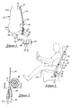
- FIGS.1 to 10 a first embodiment of a restraint belt presenter 10 according to the present invention is shown installed in a motor vehicle (not shown) having a seat 12 and an associated three-point seat belt system 14 of the type well known in the art.
- Seat 12 includes a generally upright seat back 12b for supporting the torso of a seated occupant 16 (indicated in phantom lines) and a generally horizontal seat cushion 12a projecting forwardly from the bottom portion of the seat back for supporting the pelvis and thighs of the occupant.
- the seat 12 will be referred to herein as having an inboard side and an outboard side, these terms referring to the sides of the seat adjacent to a center of a vehicle and an exterior side of a vehicle respectively, as is the case if the seat is located on the left side of the vehicle.
- This disclosure applies equally to a seat located at any position within a vehicle.
- the three-point belt assembly 14 comprises a length of flexible webbing 18 having an upper end secured to an upper anchor 20 adjacent the upper outboard portion of the seat back 12a, and a lower end secured to a lower anchor 22 adjacent the rear portion of the seat cushion 12b.
- a buckle element 24 such as a latch plate slides along the webbing 18 to allow adjustability, and is lockingly engageable with an inboard anchor (not shown) located adjacent the rear, inboard side of the seat cushion 12a.
- the webbing 18 When buckle element 24 is lockingly engaged with the inboard anchor, the webbing 18 define a lap belt and a shoulder belt in a manner well known in the art to restrain the occupant 16 in the event of a crash or other abrupt deceleration of the vehicle.
- the lap belt and shoulder belt may be formed as separate lengths of webbing connected by a fitting (not shown) that includes a buckle element engageable with the inboard anchor.
- the upper anchor 20 preferably comprises a belt retractor 26 that may be housed within seat back 12b (as shown), or mounted to a portion of the vehicle structure such as a roof rail or B-pillar as is well known in the restraints art.
- the belt retractor 26 is operative to retract the webbing 18 when it is not fastened about the occupant 16, provide for adjustment of the length of the belt for varying-sized seat occupants, and properly position the seat belt restraint system, as is well known in the art.
- the belt retractor 26 may include load limiter and/or belt pre-tensioner devices (not shown) of the type well known in the restraints art.
- Belt presenter 10 is disposed adjacent the lower anchor 22 and comprises a flexible hollow tube 28 made of a flexible, impermeable material such as woven synthetic fibers.
- the material may be similar to that used for passenger protection airbags.
- the tube 28 is constructed to have a flat, strap-like cross-section, as seen in FIG. 5, and to maintain a rolled-up, spiral configuration a helical clock spring 29 is provided.
- the clock spring 29 may be located inside of tube 28, as shown, or may be external to the tube 28 and acts so as to urge the tube 28 to a stored condition as shown in Fig.3.
- a first or bottom end of the tube 28 is secured to the vehicle and/or the seat 12 adjacent the lower anchor 22 and receives a hose 30. See FIGS. 3 and 4.
- a second or free end of the tube 28 is closed and is located at the centre of the spiral.
- a connector 32 is formed of a rigid material such as metal or plastic and is attached to the free end of tube 28. The connector 32 extends around the outside of the spiral-rolled tube 28 and encircles webbing 18, sliding freely with respect to the webbing.
- the hose 30 extends to a gas pressure source 34 (see FIG. 1), which may be located anywhere on board the vehicle.
- the pressure source 34 comprises a pressure vessel that is recharged by an air compressor (not shown).
- a valve 36 is provided to control the flow of air from the pressure source 34 into the tube 28.
- the pressure source 34 may be used solely to power the belt presenter 10, or may supply pneumatic power to other vehicle systems such as an air suspension system (not shown).
- ECS 38 controls pressure source 34 and/or valve 36 to control the flow of pressurized air from the pressure source through hose 30 into tube 28.
- ECS 38 receives signals from one or more vehicle systems, such as a seat weight sensor 40, a door status indicator switch 42, a buckle status switch 44, and an ignition switch 46.
- the three-point belt assembly 14 Prior to occupant 16 being seated in seat 12, the three-point belt assembly 14 is in the stowed position in which the belt is unfastened and belt retractor 26 draws webbing 18 upward so that it extends in a substantially straight line between upper anchor 20 and lower anchor 22.
- Belt presenter is in the stored condition shown in FIGS. 1-5 in which tube 28 is deflated and rolled into a spiral, with connector 32 encircling belt adjacent lower anchor 22. In the stored condition, belt presenter 10 allows belt assembly 14 to assume the stowed position so that it does not interfere with seat occupant 16 entering or exiting the vehicle.
- the ECS 38 is operable to activate pressure source 34 and/or valve 36 to inflate the tube 28 after occupant 16 is seated in seat 12 and ready to don the seat belt.
- ECS 38 may, for example, automatically inflate tube 28 in response to a "seat occupied" indication from seat weight sensor 40, and/or a "door closed” indication from door condition sensor 42, and/or in response to an "on” indication from ignition key 46.
- tube 28 When the tube 28 inflates it expands in cross-section so that it is no longer flat and unrolls against the force of clock spring 29, assuming a deployed condition shown in FIGS. 6-10.
- tube 28 In the deployed condition, tube 28 is relatively rigid and extends upwardly, forwardly, and inwardly with respect to the seat 12 and occupant 16.
- the connector 32 slides along the webbing 18 as the free end of tube 28 urges the belt to the presented condition.
- the occupant 16 may then grasp the webbing 18 and pull it across his/her body to fasten buckle element 24 to the inboard anchor. Movement of the belt to the presented, graspable condition may require some amount of the webbing 18 to be drawn out of retractor 26, so presenter must operate with sufficient force to overcome the winding force of the retractor 26.
- presenter In the deployed condition, presenter preferably positions the belt adjacent or above the upper surface of the occupant's thigh and far enough forward and inward for the occupant to easily see and grasp the webbing 18.
- Tube 28 remains flexible and compliant when in the inflated condition so that it does not cause any discomfort to occupant 16 if it contacts the occupant's hip or thigh as it extends inward to present the belt.
- the tube 28 is deflated and clock spring 29 urges the tube to return to its spiral-rolled, stored condition. Deflation of the tube 28 is also controlled by ECS 38, and may be triggered by buckle sensor 44 indicating that the seat belt is properly fastened, by a timer, or by any other appropriate condition or combination of conditions of vehicle systems.
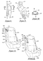
- FIGS. 11 and 12 depict a belt presenter 100 according to the invention for use with a shoulder belt 112.
- shoulder belt 112 supplements a generally conventional three-point lap/shoulder belt 114 that deploys from the opposite side of seat 116.
- three-point belt 114 is fastened to inboard anchor 115 and shoulder belt 112 is fastened to outboard anchor 113, the result is a four-point restraint belt system.
- a presenter according to the present invention may, however, be applied to any type of shoulder belt, lap belt, or combined lap/shoulder belt.
- the presenter 100 comprises an inflatable tube 117 mounted on seat back 116a adjacent an upper anchor 120, which preferably comprises a retractor (not shown) mounted inside of the seat back.
- a connector 118 secured to the end of tube 117 engages shoulder belt 112 immediately adjacent a buckle element 122 attached to the end of the shoulder belt.
- a pressure bladder 124 is disposed within the seat cushion 116b and contains a gas such as air. Pressure bladder 124 is connected with presenter 100 by a hose 126 extending through the seat. It will be appreciated that such a bladder could also be used with the first embodiment described herein to replace the pressure source 34 or vice versa.
- pressure bladder 124 When an occupant (not shown) sits on seat cushion 116b, pressure bladder 124 is compressed by the occupant's body weight, and at least a portion of the gas contained in the bladder is forced through hose 126, thereby inflating tube 117 and causing it to unroll from the spiral, stored condition shown in FIG 11, to the relatively straight deployed condition shown in FIG. 12.
- the presenter 100 may be mounted within the seat back 116a or on any vehicle structure adjacent the shoulder belt 112 and from which the presenter can, by moving from the stored condition to the deployed condition, urge the belt 112 toward a more easily grasped position.
- the presenter 100 may be mounted to a vehicle B-pillar or a roof rail adjacent the upper portion of seat back 116a.
- tube 117 deflates and returns to its stored condition.
- the deflation may be achieved by, for example, an orifice (not shown) that slowly vents the internal pressure from presenter 100, or by a valve (not shown) controlled by a timer or vehicle systems in a manner similar to that described in relation to the first embodiment of the invention and if required a spiral spring may be provided to urge the tube back to its stored condition.
- the invention belt presenter provides a simple, effective, and unobtrusive apparatus for positioning a seat belt in an easily grasped position, thereby making it more convenient and comfortable for a seat occupant to properly fasten and wear the belt.
- the presenter is compliant even when in the inflated, deployed condition so that it will not cause discomfort if it should contact the occupant. This allows the presenter to work comfortably and effectively for occupants of any size and stature.
- the present invention provides a belt presenter for use with an occupant restraint belt associated with a seat of a motor vehicle.
- the belt presenter comprises an inflatable member disposed adjacent the seat and having a stored condition wherein the member is deflated and allows the restraint belt to assume a stowed position, and a deployed condition wherein the member is inflated and urges the belt to a graspable position in which the occupant can more easily grasp the belt prior to fastening it.
- the member is inflated by a source of gas pressure carried on board the vehicle, such as a compressor, a pressure vessel, or a pressure bladder after an occupant has been seated in the seat and is ready to don the restraint belt.
- Inflation of the member preferably occurs upon activation by an electronic control system that receives inputs from one or more vehicle systems, such as a seat weight sensor, a door open/closed sensor, and/or an ignition switch.
- the member is inflated by compression of a pressure bladder contained in the seat cushion when an occupant sits in the seat.
- the inflated member is flexible and compliant enough that it will not cause any discomfort to the seat occupant if it should contact the occupant's body.
- the invention belt presenter is usable with a belt extending from a lower anchor or from an upper anchor.
- the inflatable member comprises a flexible tube attached to the motor vehicle adjacent the seat and having a free end with a connector slidably engaging the belt.
- the tube in the stored condition has a generally flat cross-section and is rolled into a spiral.
- inflation of the tube causes the tube to thicken in cross-section and to at least partially unroll such that the free end extends upwardly, forwardly, and inwardly.
- the belt slides through the connector as the tube urges the belt to the graspable position.
- a clock spring is provided to aid the tube in returning to its stored condition.
- the present invention further includes a method of moving an occupant restraint belt associated with a seat of a motor vehicle from a stowed position to a graspable position.
- the method comprises the steps of: providing an inflatable member disposed adjacent the seat and having a stored condition wherein the member is deflated and allows the restraint belt to assume the stowed position; connecting a source of gas pressure to the member, the source of gas pressure operable to selectively inflate and deflate the member; and causing the source of gas pressure to inflate the member thereby moving the member to a deployed condition wherein the member urges the belt to the graspable position.
Landscapes
- Engineering & Computer Science (AREA)
- Mechanical Engineering (AREA)
- Air Bags (AREA)
- Automotive Seat Belt Assembly (AREA)
Priority Applications (1)
| Application Number | Priority Date | Filing Date | Title |
|---|---|---|---|
| EP06127017A EP1769983B1 (fr) | 2002-04-24 | 2002-12-13 | Ensemble de présentation de ceinture de sécurité |
Applications Claiming Priority (2)
| Application Number | Priority Date | Filing Date | Title |
|---|---|---|---|
| US683682 | 1991-04-10 | ||
| US09/683,682 US6676162B2 (en) | 2002-04-24 | 2002-04-24 | Occupant restraint belt presenter |
Related Child Applications (1)
| Application Number | Title | Priority Date | Filing Date |
|---|---|---|---|
| EP06127017A Division EP1769983B1 (fr) | 2002-04-24 | 2002-12-13 | Ensemble de présentation de ceinture de sécurité |
Publications (3)
| Publication Number | Publication Date |
|---|---|
| EP1357002A2 true EP1357002A2 (fr) | 2003-10-29 |
| EP1357002A3 EP1357002A3 (fr) | 2004-08-04 |
| EP1357002B1 EP1357002B1 (fr) | 2008-04-09 |
Family
ID=28792416
Family Applications (2)
| Application Number | Title | Priority Date | Filing Date |
|---|---|---|---|
| EP02102758A Expired - Fee Related EP1357002B1 (fr) | 2002-04-24 | 2002-12-13 | Ensemble de présentation de ceinture de sécurité |
| EP06127017A Expired - Fee Related EP1769983B1 (fr) | 2002-04-24 | 2002-12-13 | Ensemble de présentation de ceinture de sécurité |
Family Applications After (1)
| Application Number | Title | Priority Date | Filing Date |
|---|---|---|---|
| EP06127017A Expired - Fee Related EP1769983B1 (fr) | 2002-04-24 | 2002-12-13 | Ensemble de présentation de ceinture de sécurité |
Country Status (3)
| Country | Link |
|---|---|
| US (1) | US6676162B2 (fr) |
| EP (2) | EP1357002B1 (fr) |
| DE (2) | DE60232038D1 (fr) |
Cited By (4)
| Publication number | Priority date | Publication date | Assignee | Title |
|---|---|---|---|---|
| WO2007012743A1 (fr) * | 2005-07-29 | 2007-02-01 | Daniel Nonat | Dispositif d'assistance a la prehension de ceinture de securite, et vehicule automobile muni d'un tel dispositif |
| DE102006042673A1 (de) * | 2006-09-12 | 2008-03-27 | Isringhausen Gmbh & Co. Kg | Verstellbare Gurtführung für den oberen Haltepunkt eines Dreipunktgurtes, Rückenlehne für einen Fahrzeugsitz sowie Verfahren zur Bewegung einer Gurtführung |
| WO2012110229A1 (fr) * | 2011-02-18 | 2012-08-23 | Trw Automotive Gmbh | Commande destinée à un dispositif de positionnement d'une ceinture de sécurité et dispositif de positionnement d'une ceinture de sécurité |
| EP2679452A1 (fr) * | 2012-06-26 | 2014-01-01 | Autoflug Gmbh | Siège de sécurité avec positionnement de la ceinture |
Families Citing this family (14)
| Publication number | Priority date | Publication date | Assignee | Title |
|---|---|---|---|---|
| JP3945763B2 (ja) * | 2002-08-30 | 2007-07-18 | 本田技研工業株式会社 | シートベルト装置の取付構造 |
| JP4573296B2 (ja) * | 2004-11-05 | 2010-11-04 | タカタ株式会社 | タング取出しシステムおよびこれを用いたシートベルト装置 |
| US7458609B2 (en) * | 2005-11-03 | 2008-12-02 | Ford Global Technologies, Llc | System and method for adjustably positioning a restraint system in a motor vehicle |
| US20070235999A1 (en) * | 2006-04-06 | 2007-10-11 | Morra Mark A | Vehicle seat belt apparatus |
| JP5121213B2 (ja) * | 2006-11-22 | 2013-01-16 | タカタ株式会社 | シートベルト装置 |
| US20090309344A1 (en) * | 2008-04-17 | 2009-12-17 | Linda Van Roosmalen | Restraint systems for use in vehicles and methods of restraint |
| US8025339B2 (en) | 2008-09-16 | 2011-09-27 | Gm Global Technology Operations, Llc | Active material based seatbelt webbing presenter |
| DE102008056823B4 (de) | 2008-11-11 | 2012-02-02 | Paul Federski | Anschnallhilfe |
| DE102011000052A1 (de) * | 2010-01-08 | 2011-07-28 | TK Holdings, Inc., Mich. | Airbag |
| JP5576453B2 (ja) * | 2012-10-16 | 2014-08-20 | 本田技研工業株式会社 | シートベルト装置 |
| JP2014148270A (ja) * | 2013-02-01 | 2014-08-21 | Autoliv Development Ab | シートベルト装置 |
| DE102016124198B4 (de) | 2016-12-13 | 2019-04-25 | Veigel Gmbh + Co. Kg | Bedienhilfe für einen Sicherheitsgurt; Sicherheitsgurt; Verfahren zur Bedienung eines Sicherheitsgurtes |
| CN107423578B (zh) * | 2017-03-02 | 2020-09-22 | 北京诺禾致源科技股份有限公司 | 检测体细胞突变的装置 |
| ES2799475B2 (es) * | 2019-06-12 | 2021-06-18 | Sumcab Inversiones S L | Sistema de retencion confortable |
Citations (3)
| Publication number | Priority date | Publication date | Assignee | Title |
|---|---|---|---|---|
| DE3444102A1 (de) * | 1984-12-04 | 1986-06-12 | Dieter 4423 Gescher König | Vorrichtung zur handlichen bereitstellung des sicherheitsgurtes in fahrzeugen |
| US4600217A (en) * | 1983-12-02 | 1986-07-15 | Audi Ag. | Apparatus for moving the tongue of a seat belt into a position for easy insertion into a buckle |
| DE3702976A1 (de) * | 1987-02-02 | 1988-08-11 | Linde & Wiemann Gmbh Kg | Sicherheitsgurt in kraftfahrzeugen |
Family Cites Families (11)
| Publication number | Priority date | Publication date | Assignee | Title |
|---|---|---|---|---|
| US3314719A (en) * | 1965-08-02 | 1967-04-18 | Edsel W Johnson | Erecting seat belt |
| FR2225012A5 (en) * | 1973-04-06 | 1974-10-31 | Hautemont Jean Claude | Automatically unrolling vehicle seat belt - has tube along belt supplied with air from bag in seat compressed by passenger |
| FR2465615A1 (en) * | 1979-09-26 | 1981-03-27 | Farah George | Safety belt for vehicle seat - includes part which is inflated by passenger weight acting on fluid pocket displacing fluid |
| DE3509984A1 (de) | 1985-03-20 | 1986-06-05 | Daimler-Benz Ag, 7000 Stuttgart | In einer tasche eines sitzteiles in seiner aussergebrauchsstellung versenkt angeordnetes gurtschloss |
| DE3530172A1 (de) | 1985-08-23 | 1987-03-05 | Daimler Benz Ag | In einer tasche eines sitzteiles versenkt angeordnetes gurtschloss |
| US5431446A (en) | 1992-08-05 | 1995-07-11 | Ford Motor Company | Seat belt presenter |
| US6692020B2 (en) * | 1998-01-16 | 2004-02-17 | Renault | Safety device for protection of a passenger of a motor vehicle, comprising a seat belt and associated inflatable air bag |
| US6237945B1 (en) | 1999-02-26 | 2001-05-29 | Lear Corporation | Passenger restraint system |
| US6193275B1 (en) * | 1999-06-01 | 2001-02-27 | Autoliv Asp, Inc. | Occupant belt presenter |
| US6382666B1 (en) * | 2000-03-13 | 2002-05-07 | Universal Propulsion Company, Inc. | Arrangement for providing deployment of inflatable member coaxially with safety belt portion and related method |
| US6485058B1 (en) * | 2000-08-04 | 2002-11-26 | Breed Automotive Technology, Inc. | Seat belt buckle and tongue presenter system |
-
2002
- 2002-04-24 US US09/683,682 patent/US6676162B2/en not_active Expired - Fee Related
- 2002-12-13 EP EP02102758A patent/EP1357002B1/fr not_active Expired - Fee Related
- 2002-12-13 DE DE60232038T patent/DE60232038D1/de not_active Expired - Lifetime
- 2002-12-13 DE DE60226008T patent/DE60226008T2/de not_active Expired - Lifetime
- 2002-12-13 EP EP06127017A patent/EP1769983B1/fr not_active Expired - Fee Related
Patent Citations (3)
| Publication number | Priority date | Publication date | Assignee | Title |
|---|---|---|---|---|
| US4600217A (en) * | 1983-12-02 | 1986-07-15 | Audi Ag. | Apparatus for moving the tongue of a seat belt into a position for easy insertion into a buckle |
| DE3444102A1 (de) * | 1984-12-04 | 1986-06-12 | Dieter 4423 Gescher König | Vorrichtung zur handlichen bereitstellung des sicherheitsgurtes in fahrzeugen |
| DE3702976A1 (de) * | 1987-02-02 | 1988-08-11 | Linde & Wiemann Gmbh Kg | Sicherheitsgurt in kraftfahrzeugen |
Cited By (7)
| Publication number | Priority date | Publication date | Assignee | Title |
|---|---|---|---|---|
| WO2007012743A1 (fr) * | 2005-07-29 | 2007-02-01 | Daniel Nonat | Dispositif d'assistance a la prehension de ceinture de securite, et vehicule automobile muni d'un tel dispositif |
| FR2889140A1 (fr) * | 2005-07-29 | 2007-02-02 | Daniel Nonat | Dispositif d'assistance a la prehension de ceinture de securite, et vehicule automobile muni d'un tel dispositif |
| DE102006042673A1 (de) * | 2006-09-12 | 2008-03-27 | Isringhausen Gmbh & Co. Kg | Verstellbare Gurtführung für den oberen Haltepunkt eines Dreipunktgurtes, Rückenlehne für einen Fahrzeugsitz sowie Verfahren zur Bewegung einer Gurtführung |
| DE102006042673B4 (de) * | 2006-09-12 | 2009-07-23 | Isringhausen Gmbh & Co. Kg | Verstellbare Gurtführung für den oberen Haltepunkt eines Dreipunktgurtes, Rückenlehne für einen Fahrzeugsitz sowie Verfahren zur Bewegung einer Gurtführung |
| WO2012110229A1 (fr) * | 2011-02-18 | 2012-08-23 | Trw Automotive Gmbh | Commande destinée à un dispositif de positionnement d'une ceinture de sécurité et dispositif de positionnement d'une ceinture de sécurité |
| US9559618B2 (en) | 2011-02-18 | 2017-01-31 | Trw Automotive Gmbh | Controller for a seatbelt positioning device and seatbelt positioning device |
| EP2679452A1 (fr) * | 2012-06-26 | 2014-01-01 | Autoflug Gmbh | Siège de sécurité avec positionnement de la ceinture |
Also Published As
| Publication number | Publication date |
|---|---|
| EP1357002B1 (fr) | 2008-04-09 |
| US6676162B2 (en) | 2004-01-13 |
| EP1769983A1 (fr) | 2007-04-04 |
| DE60232038D1 (de) | 2009-05-28 |
| DE60226008T2 (de) | 2008-07-31 |
| EP1357002A3 (fr) | 2004-08-04 |
| DE60226008D1 (de) | 2008-05-21 |
| EP1769983B1 (fr) | 2009-04-15 |
| US20030201635A1 (en) | 2003-10-30 |
Similar Documents
| Publication | Publication Date | Title |
|---|---|---|
| EP1769983B1 (fr) | Ensemble de présentation de ceinture de sécurité | |
| EP1783012B1 (fr) | Système de retenue pour véhicule | |
| US7481452B2 (en) | Occupant protection device | |
| US7293828B2 (en) | Child seat with deployable side airbags | |
| US6382666B1 (en) | Arrangement for providing deployment of inflatable member coaxially with safety belt portion and related method | |
| US9346430B2 (en) | Inflatable seatbelt | |
| EP1140566B1 (fr) | Dispositif de protection pour lits de vehicules | |
| US6688642B2 (en) | Concentrically disposed airbag system for seatbelts | |
| CA2255947A1 (fr) | Coussin allonge, tubulaire et gonflable | |
| EP1783014B1 (fr) | Système de retenue pour un véhicule automobile | |
| US11292425B2 (en) | Safety device | |
| US6550805B1 (en) | Occupant restraint belt with inflatable presenter | |
| US7789420B2 (en) | Occupant restraint apparatus | |
| JP6738005B2 (ja) | シートベルト用エアバッグ | |
| JP3502763B2 (ja) | エアベルト装置 | |
| CN211107311U (zh) | 一种汽车的安全带及汽车 | |
| CN112744178B (zh) | 包括可充气座椅安全带式约束装置的车辆安全系统 | |
| JP4513719B2 (ja) | 車両用エアベルト装置 | |
| GB2378681A (en) | Safety device for vehicle seat | |
| GB2310408A (en) | Inflatable safety belt for vehicles |
Legal Events
| Date | Code | Title | Description |
|---|---|---|---|
| PUAI | Public reference made under article 153(3) epc to a published international application that has entered the european phase |
Free format text: ORIGINAL CODE: 0009012 |
|
| AK | Designated contracting states |
Kind code of ref document: A2 Designated state(s): AT BE BG CH CY CZ DE DK EE ES FI FR GB GR IE IT LI LU MC NL PT SE SI SK TR |
|
| AX | Request for extension of the european patent |
Extension state: AL LT LV MK RO |
|
| PUAL | Search report despatched |
Free format text: ORIGINAL CODE: 0009013 |
|
| AK | Designated contracting states |
Kind code of ref document: A3 Designated state(s): AT BE BG CH CY CZ DE DK EE ES FI FR GB GR IE IT LI LU MC NL PT SE SI SK TR |
|
| AX | Request for extension of the european patent |
Extension state: AL LT LV MK RO |
|
| 17P | Request for examination filed |
Effective date: 20050103 |
|
| AKX | Designation fees paid |
Designated state(s): DE GB SE |
|
| RBV | Designated contracting states (corrected) |
Designated state(s): DE GB SE |
|
| 17Q | First examination report despatched |
Effective date: 20060821 |
|
| GRAP | Despatch of communication of intention to grant a patent |
Free format text: ORIGINAL CODE: EPIDOSNIGR1 |
|
| GRAJ | Information related to disapproval of communication of intention to grant by the applicant or resumption of examination proceedings by the epo deleted |
Free format text: ORIGINAL CODE: EPIDOSDIGR1 |
|
| 17Q | First examination report despatched |
Effective date: 20060821 |
|
| GRAP | Despatch of communication of intention to grant a patent |
Free format text: ORIGINAL CODE: EPIDOSNIGR1 |
|
| GRAS | Grant fee paid |
Free format text: ORIGINAL CODE: EPIDOSNIGR3 |
|
| GRAA | (expected) grant |
Free format text: ORIGINAL CODE: 0009210 |
|
| RAP1 | Party data changed (applicant data changed or rights of an application transferred) |
Owner name: FORD GLOBAL TECHNOLOGIES, LLC |
|
| AK | Designated contracting states |
Kind code of ref document: B1 Designated state(s): DE GB SE |
|
| REG | Reference to a national code |
Ref country code: GB Ref legal event code: FG4D |
|
| REF | Corresponds to: |
Ref document number: 60226008 Country of ref document: DE Date of ref document: 20080521 Kind code of ref document: P |
|
| REG | Reference to a national code |
Ref country code: SE Ref legal event code: TRGR |
|
| PLBE | No opposition filed within time limit |
Free format text: ORIGINAL CODE: 0009261 |
|
| STAA | Information on the status of an ep patent application or granted ep patent |
Free format text: STATUS: NO OPPOSITION FILED WITHIN TIME LIMIT |
|
| 26N | No opposition filed |
Effective date: 20090112 |
|
| REG | Reference to a national code |
Ref country code: GB Ref legal event code: 732E Free format text: REGISTERED BETWEEN 20111020 AND 20111025 |
|
| REG | Reference to a national code |
Ref country code: DE Ref legal event code: R082 Ref document number: 60226008 Country of ref document: DE Representative=s name: HANS-CARSTEN DROEMER, DE |
|
| REG | Reference to a national code |
Ref country code: DE Ref legal event code: R082 Ref document number: 60226008 Country of ref document: DE Effective date: 20120207 Representative=s name: DROEMER, HANS-CARSTEN, DIPL.-PHYS. DR.-ING., DE Ref country code: DE Ref legal event code: R081 Ref document number: 60226008 Country of ref document: DE Owner name: VOLVO CAR CORPORATION, SE Free format text: FORMER OWNER: FORD GLOBAL TECHNOLOGIES, LLC, DEARBORN, MICH., US Effective date: 20120207 Ref country code: DE Ref legal event code: R081 Ref document number: 60226008 Country of ref document: DE Owner name: VOLVO CAR CORPORATION, SE Free format text: FORMER OWNER: FORD GLOBAL TECHNOLOGIES, LLC, DEARBORN, US Effective date: 20120207 |
|
| PGFP | Annual fee paid to national office [announced via postgrant information from national office to epo] |
Ref country code: SE Payment date: 20141215 Year of fee payment: 13 Ref country code: GB Payment date: 20141209 Year of fee payment: 13 |
|
| PGFP | Annual fee paid to national office [announced via postgrant information from national office to epo] |
Ref country code: DE Payment date: 20151210 Year of fee payment: 14 |
|
| REG | Reference to a national code |
Ref country code: SE Ref legal event code: EUG |
|
| GBPC | Gb: european patent ceased through non-payment of renewal fee |
Effective date: 20151213 |
|
| PG25 | Lapsed in a contracting state [announced via postgrant information from national office to epo] |
Ref country code: SE Free format text: LAPSE BECAUSE OF NON-PAYMENT OF DUE FEES Effective date: 20151214 |
|
| PG25 | Lapsed in a contracting state [announced via postgrant information from national office to epo] |
Ref country code: GB Free format text: LAPSE BECAUSE OF NON-PAYMENT OF DUE FEES Effective date: 20151213 |
|
| REG | Reference to a national code |
Ref country code: DE Ref legal event code: R119 Ref document number: 60226008 Country of ref document: DE |
|
| REG | Reference to a national code |
Ref country code: DE Ref legal event code: R082 Ref document number: 60226008 Country of ref document: DE |
|
| PG25 | Lapsed in a contracting state [announced via postgrant information from national office to epo] |
Ref country code: DE Free format text: LAPSE BECAUSE OF NON-PAYMENT OF DUE FEES Effective date: 20170701 |