EP1355791B1 - Jante de roue en tole d'acier a profil optimise - Google Patents
Jante de roue en tole d'acier a profil optimise Download PDFInfo
- Publication number
- EP1355791B1 EP1355791B1 EP02712828A EP02712828A EP1355791B1 EP 1355791 B1 EP1355791 B1 EP 1355791B1 EP 02712828 A EP02712828 A EP 02712828A EP 02712828 A EP02712828 A EP 02712828A EP 1355791 B1 EP1355791 B1 EP 1355791B1
- Authority
- EP
- European Patent Office
- Prior art keywords
- thickness
- zone
- rim
- wheel rim
- mounting groove
- Prior art date
- Legal status (The legal status is an assumption and is not a legal conclusion. Google has not performed a legal analysis and makes no representation as to the accuracy of the status listed.)
- Expired - Lifetime
Links
- 229910000831 Steel Inorganic materials 0.000 title claims abstract description 10
- 239000010959 steel Substances 0.000 title claims abstract description 10
- 230000000063 preceeding effect Effects 0.000 claims 2
- 230000007704 transition Effects 0.000 description 13
- 238000009987 spinning Methods 0.000 description 11
- 238000004519 manufacturing process Methods 0.000 description 4
- 238000000034 method Methods 0.000 description 4
- 238000005096 rolling process Methods 0.000 description 4
- 229910052751 metal Inorganic materials 0.000 description 3
- 239000002184 metal Substances 0.000 description 3
- 230000002829 reductive effect Effects 0.000 description 3
- 230000016571 aggressive behavior Effects 0.000 description 2
- 238000006073 displacement reaction Methods 0.000 description 2
- 239000000463 material Substances 0.000 description 2
- 230000036961 partial effect Effects 0.000 description 2
- 230000002441 reversible effect Effects 0.000 description 2
- 230000004584 weight gain Effects 0.000 description 2
- 235000019786 weight gain Nutrition 0.000 description 2
- 238000003466 welding Methods 0.000 description 2
- 239000000956 alloy Substances 0.000 description 1
- 229910045601 alloy Inorganic materials 0.000 description 1
- 229910052782 aluminium Inorganic materials 0.000 description 1
- XAGFODPZIPBFFR-UHFFFAOYSA-N aluminium Chemical compound [Al] XAGFODPZIPBFFR-UHFFFAOYSA-N 0.000 description 1
- 230000006399 behavior Effects 0.000 description 1
- 230000003247 decreasing effect Effects 0.000 description 1
- 230000000694 effects Effects 0.000 description 1
- 238000009661 fatigue test Methods 0.000 description 1
- 230000000670 limiting effect Effects 0.000 description 1
- 230000002035 prolonged effect Effects 0.000 description 1
- 238000007493 shaping process Methods 0.000 description 1
Images


Classifications
-
- B—PERFORMING OPERATIONS; TRANSPORTING
- B60—VEHICLES IN GENERAL
- B60B—VEHICLE WHEELS; CASTORS; AXLES FOR WHEELS OR CASTORS; INCREASING WHEEL ADHESION
- B60B3/00—Disc wheels, i.e. wheels with load-supporting disc body
- B60B3/04—Disc wheels, i.e. wheels with load-supporting disc body with a single disc body not integral with rim, i.e. disc body and rim being manufactured independently and then permanently attached to each other in a second step, e.g. by welding
- B60B3/041—Disc wheels, i.e. wheels with load-supporting disc body with a single disc body not integral with rim, i.e. disc body and rim being manufactured independently and then permanently attached to each other in a second step, e.g. by welding characterised by the attachment of rim to wheel disc
- B60B3/044—Disc wheels, i.e. wheels with load-supporting disc body with a single disc body not integral with rim, i.e. disc body and rim being manufactured independently and then permanently attached to each other in a second step, e.g. by welding characterised by the attachment of rim to wheel disc characterised by cross-sectional details of the attachment, e.g. the profile
-
- B—PERFORMING OPERATIONS; TRANSPORTING
- B21—MECHANICAL METAL-WORKING WITHOUT ESSENTIALLY REMOVING MATERIAL; PUNCHING METAL
- B21D—WORKING OR PROCESSING OF SHEET METAL OR METAL TUBES, RODS OR PROFILES WITHOUT ESSENTIALLY REMOVING MATERIAL; PUNCHING METAL
- B21D53/00—Making other particular articles
- B21D53/26—Making other particular articles wheels or the like
- B21D53/30—Making other particular articles wheels or the like wheel rims
-
- B—PERFORMING OPERATIONS; TRANSPORTING
- B60—VEHICLES IN GENERAL
- B60B—VEHICLE WHEELS; CASTORS; AXLES FOR WHEELS OR CASTORS; INCREASING WHEEL ADHESION
- B60B21/00—Rims
- B60B21/02—Rims characterised by transverse section
Definitions
- the invention relates to sheet steel wheels having a disk and a rim with a mounting groove and assembled under this mounting groove. It relates particularly to the profile of the section of the rims of these wheels.
- the wheels of the vehicles are subjected in operation to repeated solicitations. These stresses can lead to fatigue declines. To measure the fatigue strength of the wheels, they are subjected to endurance tests on vehicles or machines.
- the test machines reproduce in a simplified and accelerated way the demands of the wheels in real use.
- the demands of the wheels depend mainly on the load of the vehicle for which the wheels are intended.
- the rims of the standard sheet steel wheels are made by a series of shaping operations of a shell of constant thickness. These rims thus have a substantially constant thickness.
- the areas of fatigue decay of these wheels are usually found at the groove bottom radii, at the joint weld and at the valve hole (see FIG. figure 1 ).
- the thickness of the sheet metal blanks intended for the manufacture of these rims is thus a function of the stresses that the wheels must undergo during operation.
- the object of the invention is the definition of the section of a rim optimized to have a high lightening while maintaining an acceptable fatigue resistance.
- the subject of the invention is a wheel rim for a motor vehicle, made of sheet steel, which comprises axially on the inner side to the outer side an inner hook, an inner seat, a connecting zone, a groove of mounting, a safety boss, an outer seat and an outer hook, this rim being intended to be assembled to a wheel disk under the mounting groove.
- This rim is characterized in that, since the rim has a given thickness E at the mounting groove, the connection zone comprises a zone of thickness E1 such that: E / 3 + 0 , 5 mm ⁇ E ⁇ 1 ⁇ E / 3 mm ; and E ⁇ 1 ⁇ 0 , 7 mm .
- the entire substantially cylindrical zone and / or frustoconical zone of the connection zone may have a thickness E1.
- the thickness E2 at the safety boss adjacent to the outer seat comprises a zone such that: E ⁇ 2 ⁇ E - 0 , 6 mm ; and E ⁇ 2 ⁇ 1 , 4 mm .
- the entire security boss may have this thickness E2.
- this zone of the safety boss which is adjacent to the side of the mounting groove through which the valve hole passes, has only a small effect on the amplitude of the stresses of the throat area. mounting.
- the proximity of the valve hole area imposes a lack of parallelism limited in this area to keep a good seal of the valve after assembly.
- the minimum thickness must be of the order of 1.4 mm.
- the wheel rim according to the invention has a thickness E3 at the inner seat which comprises a zone satisfying the following relations: E ⁇ 3 ⁇ E / 3 + 0 , 45 mm ; and E ⁇ 3 ⁇ 1 , 2 mm .
- the zone of thickness E3 may extend over the entire inner seat, including, where appropriate, the safety boss adjacent to this seat.
- the thickness in this area can also be very substantially reduced by 40 to 50% relative to the thickness in the area of the mounting groove.
- this thickness should not be reduced below 1.2 mm, in order not to risk that, for example, aggression, such as that associated with the hooks of the wheel clamps of the assembly machines, can not lead to damaging tired.
- the thickness of the wheel rim, at the level of the inner hook comprises a zone whose thickness E4 satisfies the following relation: E ⁇ 4 ⁇ E / 3 + 0 , 75 mm
- the zone of thickness E4 may comprise the zone of the orientation hook perpendicular to the axis of rotation of the wheel.
- the reduction in thickness in this zone can thus be in the order of 40 to 27% depending on the thickness of the zone of the mounting groove. It is important to respect the lower limits as specified to not degrade the behavior during fatigue tests of the wheel mounting groove. Indeed, the thickness in this area determines the rigidity of the hook of the rim.
- the outer seat of the wheel may comprise an area whose thickness E5 satisfies the following relationship: E ⁇ 5 ⁇ E / 3 + 0 , 5 mm
- This zone of thickness E5 may extend substantially to the entire outer seat.
- the thickness E at the mounting groove is between 1.9 and 2.75 mm. These thicknesses are usually used for wheel rims sheet steel passenger vehicles.
- This wheel 1 comprises a disc 2 and a rim 3.
- the rim 3 is a rim made by a set of rolling operations of a ferrule of constant thickness. This rim has a substantially constant thickness.
- This rim 3 has an inner hook 4, an inner seat 5, an inner safety boss or “hump" 6, a transition zone 7, a mounting groove 9 with an inner side 8 and an outer sidewall 10, a boss of 11, an outer seat 12 and an outer hook 13.
- the disc 2 is assembled to the rim 3 by fitting under the mounting groove 9.
- This figure also illustrates, with a partial folding, the valve hole 14 which passes through the outer flank 10 of the mounting groove 9.
- FIG. figure 2 A method of producing wheel rims according to the invention is illustrated in FIG. figure 2 .
- a sheet metal blank (not shown) of steel, aluminum or alloys is bent to give it a generally cylindrical shell 21 with two free edges.
- the shell 21 is welded by a welding process by spark, resistance or other.
- This ferrule 21 has a constant thickness ( figure 3 ).
- the ferrule 21 is then preferably calibrated in extension with the help of a calibration tool schematized in FIG. figure 4 .
- the expansion is obtained by the displacement of a cam 22 which spreads sectors 23 around which the ferrule 21 is installed.
- figure 5 illustrates the next step which consists in obtaining by cylindrical spinning the desired flat profile for the rims according to the invention.
- the flow-spinning process used is the reverse spinning.
- the ferrule 21 is mounted on a mandrel 24 and bears against a wall of the locking system of the ferrule 21.
- the mandrel 24 is then rotated and at least two rollers 26 are rolled on the radially outer surface of the ferrule 21 in areas whose thickness should be decreased.
- the rollers 26 are displaced axially in the direction of the axis X by applying a radial and tangential force so that the flow of material flows in the direction of Y. This flow of material takes place in the opposite direction of the displacement of the wheels 26.
- the figure 5 schematically illustrates an example of profile of the ferrule 21 obtained. This profile comprises five zones of constant thickness and three zones of variable thickness of transition.
- this inverse spinning process does not reduce the thickness of the entire ferrule. Indeed, it leaves on each side of the ferrule a non-flowed area: the leading side of the knurls, it could destabilize the ferrule and damage the wheels; on the side of the fastening device of the ferrule abutting, an area is left for this device can pinch the edge of the ferrule and drive it in rotation during the flow spinning operation.
- zone 15 located in the inner side 8 of the mounting groove 9 or the connection between this flank and the throat; zone 16 located under the mounting groove, near the disk-rim welding seam; zone 17 located at the connection between the mounting groove 9 and the outer flank 10 of this groove; and the zones 18 at the edge of the valve hole 14. In all these zones, cracks may appear.
- the figure 6 illustrates an example of ferrule obtained by a spinning process corresponding to the section profiles according to the invention.
- This ferrule 20 has 8 zones of constant thickness separated by 7 zones of variable thickness.
- Figures 6 and 7 allow to connect the different areas of constant and variable thicknesses to the geometry of the resulting rim 30. It should be noted that figure 6 has a scale expanded in the direction perpendicular to the axial direction relative to the axial direction.
- the zone Z2 of constant thickness E5 corresponds to the outer seat 12. Between the zones Z1 and Z2 is the zone T1, of variable thickness whose thickness varies from E to E5, going from the rim of the hook to the vertical part of this one.
- the zone Z3 substantially corresponds to the outer safety boss 11.
- the transition zone T2 is a connection between the outer seat 12 and the boss 11. This zone has a small radius of curvature.
- Zone Z4 corresponds to the prolonged mounting groove on either side of the inner and outer side regions with small radii of curvature.
- This zone Z4 has a thickness E corresponding to that of the starting flank. It should be noted that this zone includes the areas of disqualification 15, 16 and 17 specified in figure 1 . Between Z4 and Z3, there is the transition zone T3 which corresponds substantially to the outside flank 10, this zone also includes the valve hole 14 and the lapse zones 18.
- the zone Z5 corresponds to the connection zone 7.
- the transition zone T4 lies between Z4 and Z5. This transition zone substantially corresponds to the inner side 8 of the mounting groove.
- the transition zone T5 is between Z5 and Z6.
- the zone Z7 is located substantially in the vertical part (or perpendicular to the axis of rotation of the rim) of the inner hook 4. This zone is adjacent internally to T6 and outside T7.
- T6 corresponds to the axially inner end of the inner seat 5 to the vertical part of the hook 4.
- T7 corresponds to the first part of the rim of the inner hook 4.
- Zoned Z1 Z2 Z3 Z4 Z5 Z6 Z7 Z8 Relative thickness 100 64 80 100 50 73 82 100 Min-max interval 50-80 70-100 33-60 48-80 60-97
- This table indicates that the wheels of variable thickness wheels according to the invention has a main zone of reduction of thickness and weight, the zone Z5 corresponding to the connecting zone 7.
- the reduction in thickness can reach 66% relative to the thickness of the starting metal flank.
- the second zone is Z6, there the thickness reduction can reach 50%. However, it is necessary to maintain a thickness greater than 1.2 mm in order to avoid that, for example, aggression, such as those linked to the hooks of the wheel clamps of the assembly machines, can not lead to damage that is harmful to fatigue.
- a usual rim has a thickness of the order of 2.0 mm while the thickness E for a rim according to the invention.
- the invention can be 2.2 mm.
- the weight gain obtained for a rim according to the invention can reach 0.7 kg, ie of the order of 15 to 20%.
- the reduction in thickness and consequently the weight gain can in many cases be relatively greater when the thickness of the starting blank increases as well as when the diameter of the wheel increases.
- the figure 8 illustrates a second example of ferrule obtained by a flow-spinning method corresponding to the section profiles according to the invention.
- This ferrule 40 has 6 zones of constant thickness separated by 5 zones of variable thickness.
- Figures 8 and 9 allow to connect the different areas of constant and variable thicknesses to the geometry of the resulting rim 50.
- the two zones Z'1 and Z'6 correspond to the two axial ends of the shell, these two areas have the thickness E of the starting sheet flank. They correspond here to the entirety of the inner hooks 4 and outer 13 to the ends of the inner seats 5 and outer 12.
- the zone Z'2 of constant thickness E2 substantially corresponds to the outer safety boss 11. Between the zones Z'1 and Z'2 is the transition zone T'1 which corresponds to the outer seat 12.
- the zones Z'3 and Z'4 respectively correspond to the mounting groove 9 increased areas of small radius of curvature of the sides 9 and 8 of the groove and to the connecting zone 7.
- the thickness of the zone Z'3 is E
- that of the zone Z'4 is E1.
- transition zone T'2 which substantially corresponds to the zone of the valve hole of the sidewall 10.
- transition zone T'3 corresponding to substantially to the area of small radius of curvature comprising the axially outer end of the connecting zone 7 and the axially inner end of the inner side 8 of the mounting groove 9.
- the zone Z'5 substantially corresponds to the inner boss 6. Its thickness is E3. Between Z'4 and Z'5 is the transition zone T'4, of short length.
- transition zone T'5 which substantially corresponds to the inner seat 5.
- FIG. 8 and 9 is a simplified example of rim profile according to the invention in which, in fact, the profile between the axially outer end of the inner seat 6 and the axially inner end of the outer seat 12 is identical to that of the rim 30.
- the simplification comes from the constant thickness profile of the two inner and outer hooks which stiffens them. Consequently, the thickness of the starting blank of this rim can be compared with that of a standard rim of constant thickness. This profile thus makes it possible to obtain a substantially identical lightening of the weight of the rim.
Landscapes
- Engineering & Computer Science (AREA)
- Mechanical Engineering (AREA)
- Shaping Metal By Deep-Drawing, Or The Like (AREA)
- Heat Treatment Of Articles (AREA)
- Tires In General (AREA)
- Connection Of Plates (AREA)
- Braking Arrangements (AREA)
- Steering Controls (AREA)
- Pulleys (AREA)
Description
- L'invention concerne les roues en tôle d'acier comportant un disque et une jante avec une gorge de montage et assemblés sous cette gorge de montage. Elle concerne particulièrement le profil de la section des jantes de ces roues.
- Les roues des véhicules sont soumises en fonctionnement à des sollicitations répétées. Ces sollicitations peuvent entraîner des déchéances par fatigue. Pour mesurer la tenue en fatigue des roues, on soumet celles-ci à des tests d'endurance sur véhicules ou sur machines. Les machines de tests reproduisent de façon simplifiée et en accéléré les sollicitations des roues en usage réel. Les sollicitations des roues dépendent principalement de la charge du véhicule auquel sont destinées les roues.
- Les jantes des roues en tôle d'acier standards sont réalisées par une série d'opérations de mise en forme d'une virole d'épaisseur constante. Ces jantes ont ainsi une épaisseur sensiblement constante. Les zones de déchéances en fatigue de ces roues se trouvent usuellement au niveau des rayons de fond de gorge, au niveau de la soudure d'assemblage et au niveau du trou de valve (voir
figure 1 ). - L'épaisseur des flans de départ en tôle destinés à la fabrication de ces jantes est ainsi fonction des sollicitations que les roues doivent subir en fonctionnement.
- Le brevet
US 5 579 578 présente une méthode de fabrication d'une jante de roue comportant une ou plusieurs opérations de fluotournage cylindrique inverse pour obtenir un profil de jante d'épaisseur variable et ainsi pouvoir diminuer le poids de la jante. Ce brevet ne donne aucune information sur les profils des sections des jantes à obtenir. Ce document forme l'état de la technique le plus proche sur lequel le préambule de la revendication 1 est fondé. - L'invention a pour objet la définition de la section d'une jante optimisée pour avoir un allègement élevé tout en conservant une résistance à la fatigue acceptable.
- Selon un premier aspect, l'invention a pour objet une jante de roue pour véhicule automobile, en tôle d'acier, qui comporte axialement du côté intérieur au côté extérieur un crochet intérieur, un siège intérieur, une zone de liaison, une gorge de montage, un bossage de sécurité, un siège extérieur et un crochet extérieur, cette jante étant destinée à être assemblée à un disque de roue sous la gorge de montage. Cette jante est caractérisée en ce que, la jante ayant une épaisseur donnée E au niveau de la gorge de montage, la zone de liaison comporte une zone d'épaisseur E1 telle que :


- L'ensemble de la zone sensiblement cylindrique et/ou tronconique de la zone de liaison peut avoir une épaisseur E1.
- Ces relations montrent que l'épaisseur de la jante, sur tout ou partie de la zone de liaison, peut être réduite jusqu'à sensiblement le tiers de l'épaisseur au niveau de la gorge de montage. Cette très forte réduction d'épaisseur procure un allègement très sensible de la jante, même si une jante ainsi optimisée a une épaisseur au niveau de la gorge de montage supérieure à celle d'une jante comparable mono épaisseur.
- Avantageusement, l'épaisseur E2 au niveau du bossage de sécurité adjacent au siège extérieur comporte une zone telle que :

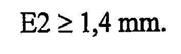
- L'ensemble du bossage de sécurité peut avoir cette épaisseur E2.
- On constate que l'épaisseur de cette zone du bossage de sécurité, adjacente extérieurement au flanc de la gorge de montage dans lequel passe le trou de valve n'a que peu d'incidence sur l'amplitude des sollicitations de la zone de la gorge de montage. En revanche, la proximité de la zone du trou de valve impose un défaut de parallélisme limité dans cette zone pour garder une bonne étanchéité de la valve après son montage. L'épaisseur minimale doit être de l'ordre de 1,4 mm.
- Avantageusement, la jante de roue selon l'invention a une épaisseur E3 au niveau du siège intérieur qui comporte une zone satisfaisant aux relations suivantes :


- La zone d'épaisseur E3 peut s'étendre sur l'ensemble du siège intérieur, y compris, le cas échéant, au bossage de sécurité adjacent à ce siège.
- Ces relations indiquent que l'épaisseur dans cette zone peut aussi être très substantiellement réduite, de 40 à 50 % relativement à l'épaisseur dans la zone de la gorge de montage. Il convient cependant de ne pas diminuer cette épaisseur en deçà de 1,2 mm, pour ne pas risquer que, par exemple des agressions, telles celles liées aux crochets des pinces de serrage des roues des machines de montage ne puissent entraîner des endommagements dommageables en fatigue.
- De préférence, on a : E3 ≤ E/3 + 0,9 mm. Cela contribue à l'allègement de la jante.
- Avantageusement, l'épaisseur de la jante de roue, au niveau du crochet intérieur comporte une zone dont l'épaisseur E4 satisfait la relation suivante :

- Et de préférence,

- La zone d'épaisseur E4 peut comporter la zone du crochet d'orientation perpendiculaire à l'axe de rotation de la roue.
- La réduction d'épaisseur dans cette zone peut ainsi atteindre de l'ordre de 40 à 27 % en fonction de l'épaisseur de la zone de la gorge de montage. Il est important de respecter les limites inférieures telles que précisées pour ne pas dégrader la tenue lors des tests de fatigue de la gorge de montage de la roue. En effet, l'épaisseur dans cette zone conditionne la rigidité du crochet de la jante.
- Enfin, le siège extérieur de la roue peut comporter une zone dont l'épaisseur E5 satisfait à la relation suivante :

- De préférence, dans un but d'allègement de la jante, on a aussi :

- Cette zone d'épaisseur E5 peut s'étendre sensiblement à l'ensemble du siège extérieur.
- De préférence, l'épaisseur E au niveau de la gorge de montage est comprise entre 1,9 et 2,75 mm. Ces épaisseurs sont usuellement utilisées pour les jantes de roues en tôle d'acier des véhicules de tourisme.
- Un mode de réalisation particulier de l'invention est maintenant décrit, à titre non limitatif, à l'aide du dessin annexé dans lequel :
- la
figure 1 est une vue schématique d'une roue mono épaisseur indiquant les zones de rupture possibles en fatigue ; - la
figure 2 présente les différentes étapes du procédé de réalisation d'une jante selon l'invention ; - les
figures 3, 4 et 5 illustrent schématiquement différentes étapes du procédé de réalisation présenté à lafigure 2 ; - la
figure 6 est une vue en coupe méridienne d'une virole de jante selon l'invention à l'issue d'un ensemble d'opérations de fluotournage ; - la
figure 7 est une vue en coupe méridienne de la jante correspondant à la virole de lafigure 6 , après les opérations de profilage par roulage ; - la
figure 8 est une vue en coupe méridienne d'un second mode de réalisation d'une virole de jante selon l'invention à l'issue d'un ensemble d'opérations de fluotournage ; et - la
figure 9 est une vue en coupe méridienne de la jante correspondant à la virole de lafigure 8 , après les opérations de profilage par roulage. - A la
figure 1 est présentée une coupe partielle d'une roue usuelle en tôle d'acier. Cette roue 1 comprend un disque 2 et une jante 3. - La jante 3 est une jante réalisée par un ensemble d'opérations de roulage d'une virole d'épaisseur constante. Cette jante a sensiblement une épaisseur constante. Cette jante 3 présente un crochet intérieur 4, un siège intérieur 5, un bossage de sécurité ou " hump " intérieur 6, une zone de transition 7, une gorge de montage 9 avec un flanc intérieur 8 et un flanc extérieur 10, un bossage de sécurité extérieur 11, un siège extérieur 12 et un crochet extérieur 13. Le disque 2 est assemblé à la jante 3 par emboîtage sous la gorge de montage 9. Cette figure illustre aussi, avec un rabattement partiel, le trou de valve 14 qui traverse le flanc 10 extérieur de la gorge de montage 9.
- Dans ce qui suit, on utilisera les mêmes références pour les parties similaires des jantes de roues selon l'invention.
- Un procédé de réalisation des jantes des roues selon l'invention est illustré à la
figure 2 . Initialement, un flan de tôle métallique (non représenté) d'acier, d'aluminium ou d'alliages, est cintré pour lui donner une forme généralement cylindrique de virole 21 avec deux bords libres. Ensuite, la virole 21 est soudée par un procédé de soudure par étincelage, par résistance ou autre. Cette virole 21 a une épaisseur constante (figure 3 ). La virole 21 est ensuite, de préférence, calibrée en extension à l'aide d'un outil de calibrage schématisé à lafigure 4 . L'expansion est obtenue par le déplacement d'une came 22 qui écarte des secteurs 23 autour desquels est installée la virole 21. Lafigure 5 illustre l'étape suivante qui consiste à obtenir par fluotournage cylindrique le profil à plat recherché pour les jantes selon l'invention. Le procédé de fluotournage utilisé est le fluotournage inverse. La virole 21 est montée sur un mandrin 24 et vient en appui contre une paroi du système 25 de blocage de la virole 21. Le mandrin 24 est alors mis en rotation et au moins deux molettes 26 viennent rouler sur la surface radialement extérieure de la virole 21 dans les zones dont l'épaisseur doit être diminuée. Relativement au mandrin 24, les molettes 26 sont déplacées axialement dans la direction de l'axe X en appliquant un effort radial et tangentiel de telle sorte que le flux de matière flue en direction de Y. Ce fluage de matière s'effectue en sens inverse du déplacement des molettes 26. Lafigure 5 illustre schématiquement un exemple de profil de la virole 21 obtenu. Ce profil comprend cinq zones d'épaisseurs constantes et trois zones d'épaisseurs variables de transition. - Il est à noter que ce procédé de fluotournage inverse ne permet pas de réduire l'épaisseur de l'intégralité de la virole. En effet, on laisse de chaque côté de la virole une zone non fluotournée : du côté d'attaque des molettes, cela risquerait de déstabiliser la virole et d'endommager les molettes ; du côté du dispositif de fixation de la virole faisant butée, on laisse une zone pour que ce dispositif puisse pincer le bord de la virole et l'entraîner en rotation lors de l'opération de fluotournage.
- Après avoir achevé les opérations de fluotournage, on peut découper, si nécessaire, l'un ou les deux bords de la virole, puis on évase la virole, on effectue des opérations de roulage de la virole pour obtenir le profil de jante recherché (voir
fig. 7 ), on calibre la jante et on réalise l'emboîtage avec des disques appropriés. - A la
figure 1 sont aussi schématiquement indiquées les zones possibles de déchéances en fatigue de la jante 3 de la roue 1. Ces zones sont les suivantes : la zone 15 située dans le flanc intérieur 8 de la gorge de montage 9 ou à la liaison entre ce flanc et la gorge ; la zone 16 située sous la gorge de montage, à proximité du cordon de soudure disque-jante ; la zone 17 située à la liaison entre la gorge de montage 9 et le flanc extérieur 10 de cette gorge ; et les zones 18 en bordure du trou de valve 14. Dans toutes ces zones, on peut voir apparaître des fissures. - La
figure 6 illustre un exemple de virole obtenue par un procédé de fluotournage correspondant aux profils des sections selon l'invention. - Cette virole 20 présente 8 zones d'épaisseurs constantes séparées par 7 zones d'épaisseurs variables.
- Les
figures 6 et 7 permettent de relier les différentes zones d'épaisseurs constantes et variables à la géométrie de la jante 30 en résultant. Il est à noter que lafigure 6 a une échelle dilatée dans la direction perpendiculaire à la direction axiale relativement à la direction axiale. - Les deux zones Z1 et Z8, d'épaisseurs constantes égale à l'épaisseur E du flanc de tôle d'acier de départ correspondent aux deux extrémités axiales des rebords des crochets 13 et 4.
- La zone Z2 d'épaisseur constante E5 correspond au siège extérieur 12. Entre les zones Z1 et Z2 se trouve la zone T1, d'épaisseur variable dont l'épaisseur varie de E à E5 en allant du rebord du crochet à la partie verticale de celui-ci.
- On trouve ensuite une zone de transition T2 entre les zones Z2 et Z3. La zone Z3 correspond sensiblement au bossage de sécurité extérieur 11. La zone de transition T2 est une liaison entre le siège extérieur 12 et le bossage 11. Cette zone a un faible rayon de courbure.
- La zone Z4 correspond à la gorge de montage prolongée de part et d'autre des zones des flancs intérieur et extérieur à faibles rayons de courbure. Cette zone Z4 a une épaisseur E correspondant à celle du flanc de départ. Il est à noter que cette zone inclus les zones de déchéances 15, 16 et 17 précisées à la
figure 1 . Entre Z4 et Z3, se trouve la zone de transition T3 qui correspond sensiblement au flanc extérieur 10, cette zone inclus aussi le trou de valve 14 et les zones de déchéances 18. - La zone Z5 correspond à la zone de liaison 7. La zone de transition T4 se trouve entre Z4 et Z5. Cette zone de transition correspond sensiblement au flanc intérieur 8 de la gorge de montage.
- On a ensuite la zone Z6 correspondant sensiblement au siège intérieur 5 et au bossage de sécurité intérieur 6. La zone de transition T5 est entre Z5 et Z6.
- La zone Z7 se trouve placée sensiblement dans la partie verticale (ou perpendiculaire à l'axe de rotation de la jante) du crochet intérieur 4. Cette zone est adjacente intérieurement à T6 et extérieurement à T7. T6 correspond à l'extrémité axialement intérieure du siège intérieur 5 jusqu'à la partie verticale du crochet 4. T7 correspond à la première partie du rebord du crochet intérieur 4. Enfin, on a la zone Z8 d'épaisseur constante correspondant au bord intérieur du rebord du crochet 4.
- Le tableau suivant présente les épaisseurs relatives des différentes zones Z1 à Z8 dans l'exemple des
figures 6 et 7 , en prenant comme référence à 100 l'épaisseur E initiale du flanc de départ, ainsi que les intervalles de valeurs préconisées en prenant comme référence les épaisseurs du flanc de départ comprises entre 1,9 et 2,75 mm.Zone Z1 Z2 Z3 Z4 Z5 Z6 Z7 Z8 Epaisseur relative 100 64 80 100 50 73 82 100 Intervalle mini-maxi 50-80 70-100 33-60 48-80 60-97 - Ce tableau indique que les jantes de roues à épaisseur variable selon l'invention présente une zone principale de réduction d'épaisseur et de poids, la zone Z5 correspondant à la zone de liaison 7. La réduction d'épaisseur peut atteindre 66 % relativement à l'épaisseur du flanc métallique de départ.
- La seconde zone est Z6, là la réduction d'épaisseur peut atteindre 50 %. Il est cependant nécessaire de conserver une épaisseur supérieure à 1,2 mm pour éviter que, par exemple des agressions, telles celles liées aux crochets des pinces de serrage des roues des machines de montage ne puissent entraîner des endommagements dommageables en fatigue.
Dans le cas d'une roue de dimensions 6,5 J 15 H2, pour un cahier des charges donné, une jante usuelle a une épaisseur de l'ordre de 2,0 mm alors que l'épaisseur E pour une jante selon l'invention peut être de 2,2 mm. Pour de telles roues, le gain de poids obtenu pour une jante selon l'invention peut atteindre 0,7 kg, soit de l'ordre de 15 à 20 %. - Il est à noter que la réduction d'épaisseur et en conséquence le gain de poids, peuvent dans de nombreux cas être relativement supérieurs lorsque l'épaisseur du flan de départ augmente ainsi que lorsque le diamètre de la roue augmente.
- La
figure 8 illustre un second exemple de virole obtenue par un procédé de fluotournage correspondant aux profils des sections selon l'invention. - Cette virole 40 présente 6 zones d'épaisseurs constantes séparées par 5 zones d'épaisseurs variables.
- Comme précédemment, les
figures 8 et 9 permettent de relier les différentes zones d'épaisseurs constantes et variables à la géométrie de la jante 50 en résultant. - Les deux zones Z'1 et Z'6 correspondent aux deux extrémités axiales de la virole, ces deux zones ont l'épaisseur E du flanc de tôle de départ. Elles correspondent ici à l'intégralité des crochets intérieur 4 et extérieur 13 jusqu'aux extrémités des sièges intérieur 5 et extérieur 12.
- La zone Z'2 d'épaisseur constante E2 correspond sensiblement au bossage de sécurité extérieur 11. Entre les zones Z'1 et Z'2 se trouve la zone de transition T'1 qui correspond au siège extérieur 12.
- Les zones Z'3 et Z'4 correspondent respectivement à la gorge de montage 9 augmentée des zones à faible rayon de courbure des flancs 9 et 8 de la gorge et à la zone de liaison 7. L'épaisseur de la zone Z'3 est E, celle de la zone Z'4 est E1.
- Entre Z'2 et Z'3 se trouve la zone de transition T'2 qui correspond sensiblement à la zone du trou de valve du flanc 10. Entre Z'3 et Z'4 se trouve la zone de transition T'3 qui correspond sensiblement à la zone de faible rayon de courbure comprenant l'extrémité axialement extérieure de la zone de liaison 7 et l'extrémité axialement intérieure du flanc intérieur 8 de la gorge de montage 9.
- La zone Z'5 correspond sensiblement au bossage intérieur 6. Son épaisseur est E3. Entre Z'4 et Z'5 se trouve la zone de transition T'4, de faible longueur.
- Enfin entre la zone Z'6 et la zone Z'5 se trouve la zone de transition T'5 qui correspond sensiblement au siège intérieur 5.
- L'exemple des
figures 8 et 9 est un exemple simplifié de profil de jante selon l'invention dans lequel, en fait, le profil compris entre l'extrémité axialement extérieure du siège intérieur 6 et l'extrémité axialement intérieure du siège extérieur 12 est identique à celui de la jante 30. La simplification provient du profil à épaisseur constante des deux crochets intérieur et extérieur ce qui les rigidifie. En conséquence on peut rapprocher l'épaisseur du flan de départ de cette jante de celle d'une jante standard d'épaisseur constante. Ce profil permet ainsi d'obtenir un allègement sensiblement identique du poids de la jante. - L'exemple des
figures 6 à 9 n'est à considérer que comme des exemples non limitatifs de la portée de l'invention. On peut en effet faciliter notablement la réalisation du profil à plat de la virole par fluotournage en définissant un profil avec moins de zones d'épaisseurs différentes, 4 ou 5 par exemple.
Claims (17)
- Jante (30, 50) de roue pour véhicule automobile, en tôle d'acier, comportant axialement du côté intérieur au côté extérieur un crochet intérieur (4), un siège intérieur (5), une zone de liaison (7), une gorge de montage (9), un bossage de sécurité (11), un siège extérieur (5) et un crochet extérieur (13), ladite jante étant destinée à être assemblée à un disque (2) de roue sous la gorge de montage (9), caractérisée en ce que, ladite jante ayant une épaisseur donnée E au niveau de ladite gorge de montage (9), la zone de liaison (7) comporte une zone (Z5, Z'4) d'épaisseur E1 telle que :


- Jante (30, 50) selon la revendication 1, dans laquelle l'ensemble de la zone de liaison (7) a une épaisseur E1.
- Jante (30, 50) de roue selon l'une des revendications 1 et 2, dans laquelle l'épaisseur E2 au niveau du bossage de sécurité extérieur (11) comporte une zone (Z3, Z'2) satisfaisant aux relations suivantes :


- Jante (30, 50) de roue selon la revendication 3, dans laquelle la zone (Z3, Z'2) d'épaisseur E2 s'étend sensiblement sur l'ensemble du bossage de sécurité extérieur (11).
- Jante (30) de roue selon l'une des revendications 1 à 4, dans laquelle l'épaisseur E3 au niveau du siège intérieur (5) comporte une zone (Z6) satisfaisant aux relations suivantes :


- Jante (30) de roue selon la revendication 5, dans laquelle :

- Jante (30) de roue selon l'une des revendications 5 et 6, dans laquelle l'ensemble du siège intérieur (5) a une épaisseur E3.
- Jante (30) de roue selon la revendication 7, dans laquelle, la jante comportant un bossage de sécurité intérieur (6), la zone (Z6) d'épaisseur E3 comprend l'ensemble de ce bossage.
- Jante (30) de roue selon l'une des revendications 1 à 8, dans laquelle l'épaisseur au niveau du crochet intérieur (4) comporte une zone (Z7) dont l'épaisseur E4 satisfait la relation suivante :

- Jante (30) de roue selon la revendication 9, dans laquelle :

- Jante (30) de roue selon l'une des revendications 8 et 9, dans laquelle la zone (Z7) du crochet d'épaisseur E4 comporte la zone du crochet d'orientation perpendiculaire à l'axe de rotation de la roue.
- Jante (30) de roue selon l'une des revendications 1 à 11, dans laquelle le siège extérieur (12) comporte une zone (Z2) d'épaisseur E5 telle que :

- Jante (30) de roue selon la revendication 12, dans laquelle l'épaisseur E5 est telle que :

- Jante (30) de roue selon l'une des revendications 12 et 13, dans laquelle la zone (Z2) du siège extérieur (12) d'épaisseur E5 s'étend sensiblement sur l'ensemble du siège extérieur.
- Jante (30) de roue selon la revendication 14, dans laquelle la zone (Z2) d'épaisseur E5 s'étend jusqu'à la zone du crochet extérieur (12) d'orientation perpendiculaire à l'axe de rotation de la roue.
- Jante (30, 50) de roue selon l'une des revendications précédentes, dans laquelle l'épaisseur E au niveau de la gorge de montage (9) est comprise entre 1,9 et 2,75 mm.
- Jante (30, 50) de roue selon l'une des revendications précédentes dans laquelle les variations d'épaisseur sont obtenues par des opérations de fluotournage.
Applications Claiming Priority (3)
| Application Number | Priority Date | Filing Date | Title |
|---|---|---|---|
| FR0100968 | 2001-01-23 | ||
| FR0100968A FR2819741A1 (fr) | 2001-01-23 | 2001-01-23 | Jante de roue en tole d'acier a profil optimise |
| PCT/EP2002/000545 WO2002058946A1 (fr) | 2001-01-23 | 2002-01-21 | Jante de roue en tole d'acier a profil optimise |
Publications (2)
| Publication Number | Publication Date |
|---|---|
| EP1355791A1 EP1355791A1 (fr) | 2003-10-29 |
| EP1355791B1 true EP1355791B1 (fr) | 2008-07-23 |
Family
ID=8859203
Family Applications (1)
| Application Number | Title | Priority Date | Filing Date |
|---|---|---|---|
| EP02712828A Expired - Lifetime EP1355791B1 (fr) | 2001-01-23 | 2002-01-21 | Jante de roue en tole d'acier a profil optimise |
Country Status (9)
| Country | Link |
|---|---|
| US (1) | US7014274B2 (fr) |
| EP (1) | EP1355791B1 (fr) |
| JP (1) | JP2004522636A (fr) |
| AT (1) | ATE402027T1 (fr) |
| BR (1) | BR0206649B1 (fr) |
| DE (1) | DE60227779D1 (fr) |
| ES (1) | ES2311053T3 (fr) |
| FR (1) | FR2819741A1 (fr) |
| WO (1) | WO2002058946A1 (fr) |
Families Citing this family (17)
| Publication number | Priority date | Publication date | Assignee | Title |
|---|---|---|---|---|
| JP4188029B2 (ja) * | 2002-08-23 | 2008-11-26 | 横浜ゴム株式会社 | タイヤ用ホイール |
| JP4076451B2 (ja) * | 2003-01-28 | 2008-04-16 | トピー工業株式会社 | 不等厚リム用リム素材、不等厚リム、不等厚リムの製造方法 |
| DE102006048528A1 (de) | 2006-10-13 | 2008-04-17 | Volkswagen Ag | Stahlrad und Verfahren zu dessen Herstellung |
| WO2009057128A2 (fr) * | 2007-11-01 | 2009-05-07 | Wheels India Limited | Roues de véhicule comprenant des jantes d'épaisseur non constante |
| JP4633781B2 (ja) * | 2007-12-18 | 2011-02-16 | トピー工業株式会社 | 不等厚リム用リム素材および不等厚リムの製造方法 |
| DK2106927T3 (da) * | 2008-04-04 | 2012-04-02 | Gkn Land Systems Ltd | Hjulkonstruktion. |
| JP5452593B2 (ja) * | 2009-06-05 | 2014-03-26 | 中央精機株式会社 | 自動車用ホイール |
| EP2374631B1 (fr) * | 2010-04-09 | 2013-03-20 | Iochpe-Maxion S.A. | Roue d'acier pour des pneus sans chambre à air |
| EP2671725B1 (fr) * | 2011-02-04 | 2015-09-30 | Bridgestone Corporation | Jante pour pneumatique |
| CN103963561A (zh) * | 2014-04-21 | 2014-08-06 | 蚌埠市福沃特车轮制造科技有限公司 | 一种新型的车轮钢圈 |
| KR101598903B1 (ko) * | 2015-10-20 | 2016-03-02 | 주식회사 지티물류 | 차량용 방진휠 |
| KR101625375B1 (ko) * | 2016-02-19 | 2016-05-30 | 주식회사 지티물류 | 림부가 개선된 차량용 방진휠 |
| DE102016117510A1 (de) | 2016-09-16 | 2018-03-22 | Maxion Wheels Germany Holding Gmbh | Verfahren zur Herstellung von Steilschulterfelgen, Steilschulterfelge und Fahrzeugrad hiermit für Nutzfahrzeuge |
| DE202020100517U1 (de) * | 2020-01-30 | 2021-06-10 | Maxion Wheels Holding Gmbh | Felge für Fahrzeugrad und Fahrzeugrad hiermit |
| US20240375432A1 (en) * | 2023-05-08 | 2024-11-14 | Maxion Wheels Holding Gmbh | Vehicle wheel rim, vehicle wheel including such a wheel rim and method for producing such a wheel rim and vehicle wheel |
| US20240375430A1 (en) * | 2023-05-08 | 2024-11-14 | Maxion Wheels Holding Gmbh | Vehicle wheel and method for producing such a wheel |
| US20240375433A1 (en) * | 2023-05-08 | 2024-11-14 | Maxion Wheels Holding Gmbh | Vehicle wheel rim, vehicle wheel including such a wheel rim and method for producing such a wheel rim and vehicle wheel |
Family Cites Families (10)
| Publication number | Priority date | Publication date | Assignee | Title |
|---|---|---|---|---|
| US2083326A (en) * | 1934-10-08 | 1937-06-08 | Budd Wheel Co | Vehicle wheel |
| US2200361A (en) * | 1937-10-20 | 1940-05-14 | Motor Wheel Corp | Vehicle wheel |
| FR1598727A (fr) * | 1968-12-24 | 1970-07-06 | ||
| US4088372A (en) * | 1976-05-21 | 1978-05-09 | Deere & Company | Unitary wheel for industrial use |
| DE2624873A1 (de) * | 1976-06-03 | 1977-12-08 | Bohner & Koehle | Verfahren zum herstellen von ungeteilten felgen |
| US4962587A (en) * | 1989-04-21 | 1990-10-16 | Kelsey-Hayes Company | Method of making a wheel rim |
| US5579578A (en) | 1993-10-27 | 1996-12-03 | Hayes Wheels International, Inc. | Method for producing a rim for a vechicle wheel |
| DE19548109A1 (de) * | 1995-12-21 | 1997-06-26 | Suedrad Autoraeder | Felge und Verfahren zu ihrer Herstellung |
| DE19721860A1 (de) * | 1996-05-22 | 1997-11-27 | Mannesmann Ag | Geschweißtes Fahrzeugrad |
| ES2200774T3 (es) * | 1999-12-09 | 2004-03-16 | Societe De Technologie Michelin | Rueda de vehiculo utilitario con valvula que desemboca fuera del disco. |
-
2001
- 2001-01-23 FR FR0100968A patent/FR2819741A1/fr active Pending
-
2002
- 2002-01-21 DE DE60227779T patent/DE60227779D1/de not_active Expired - Lifetime
- 2002-01-21 EP EP02712828A patent/EP1355791B1/fr not_active Expired - Lifetime
- 2002-01-21 WO PCT/EP2002/000545 patent/WO2002058946A1/fr not_active Ceased
- 2002-01-21 AT AT02712828T patent/ATE402027T1/de active
- 2002-01-21 BR BRPI0206649-1A patent/BR0206649B1/pt not_active IP Right Cessation
- 2002-01-21 ES ES02712828T patent/ES2311053T3/es not_active Expired - Lifetime
- 2002-01-21 JP JP2002559259A patent/JP2004522636A/ja active Pending
-
2003
- 2003-07-22 US US10/624,990 patent/US7014274B2/en not_active Expired - Lifetime
Also Published As
| Publication number | Publication date |
|---|---|
| BR0206649A (pt) | 2004-02-25 |
| DE60227779D1 (de) | 2008-09-04 |
| EP1355791A1 (fr) | 2003-10-29 |
| BR0206649B1 (pt) | 2011-04-19 |
| JP2004522636A (ja) | 2004-07-29 |
| WO2002058946A1 (fr) | 2002-08-01 |
| ATE402027T1 (de) | 2008-08-15 |
| US20040124695A1 (en) | 2004-07-01 |
| ES2311053T3 (es) | 2009-02-01 |
| US7014274B2 (en) | 2006-03-21 |
| FR2819741A1 (fr) | 2002-07-26 |
Similar Documents
| Publication | Publication Date | Title |
|---|---|---|
| FR2819741A1 (fr) | Jante de roue en tole d'acier a profil optimise | |
| EP1097823B1 (fr) | Jante destinée à recevoir un anneau de soutien | |
| EP1378402B1 (fr) | Profilé pour élément de structure de véhicule automobile, et châssis correspondant | |
| EP1481756B1 (fr) | Procédé de fabrication d'une aube creuse pour turbomachine | |
| EP1588867A1 (fr) | Jante presentant des inegalites d'epaisseur, et son procede de fabrication | |
| EP1299251B1 (fr) | Roue pour vehicule a assemblage sous siege | |
| EP0755807A2 (fr) | Roue de véhicule utilitaire à valve débouchant à l'extérieur du disque | |
| CA2514106A1 (fr) | Procede de fabrication de pieces constitutives d'une aube creuse par laminage | |
| EP1335805B1 (fr) | Procede de fabrication d'une jante de roue de vehicule | |
| EP1540229B1 (fr) | Collier de serrage | |
| EP1167076A1 (fr) | Voile de roue allégé et à large espace frein | |
| FR2521884A1 (fr) | Procede de fabrication de roues en alliage leger pour vehicules automobiles en general et roues obtenues par ce procede | |
| CN1517239A (zh) | 具有空心凸缘部的轮辋的制造方法 | |
| JP3373018B2 (ja) | 自動車ホイール用リムの製造方法 | |
| JPH0891005A (ja) | 自動車ホイール用リムの製造方法 | |
| EP1192016A1 (fr) | Procede d'assemblage d'au moins deux elements constitutifs en metal en vue de creer une structure | |
| EP1831035B1 (fr) | Bourrelet de pneumatique facilitant le montage et methode de construction d'un tel bourrelet | |
| EP1625026A2 (fr) | Nouvelle roue notamment en alliage leger pour vehicule automobile, et procede de fabrication d'une telle roue | |
| WO2004005049A1 (fr) | Jante de roue constituee de deux structures assemblees | |
| JP3998560B2 (ja) | 自動車用軽量化ホイール | |
| FR2605937A1 (fr) | Roue de vehicule equipee d'un pneumatique monte sur la face interieure radiale de la jante | |
| FR2744069A1 (fr) | Roue de vehicule utilitaire a valve debouchant a l'exterieur du disque | |
| BE419495A (fr) | ||
| FR2820083A1 (fr) | Roue de vehicule optimisee en masse et en fatigue | |
| FR2741930A1 (fr) | Element de poulie pour courroie en v et procede de fabrication |
Legal Events
| Date | Code | Title | Description |
|---|---|---|---|
| PUAI | Public reference made under article 153(3) epc to a published international application that has entered the european phase |
Free format text: ORIGINAL CODE: 0009012 |
|
| 17P | Request for examination filed |
Effective date: 20030825 |
|
| AK | Designated contracting states |
Kind code of ref document: A1 Designated state(s): AT BE CH CY DE DK ES FI FR GB GR IE IT LI LU MC NL PT SE TR |
|
| AX | Request for extension of the european patent |
Extension state: AL LT LV MK RO SI |
|
| RAP1 | Party data changed (applicant data changed or rights of an application transferred) |
Owner name: MEFRO ROUES FRANCE |
|
| GRAP | Despatch of communication of intention to grant a patent |
Free format text: ORIGINAL CODE: EPIDOSNIGR1 |
|
| GRAS | Grant fee paid |
Free format text: ORIGINAL CODE: EPIDOSNIGR3 |
|
| GRAA | (expected) grant |
Free format text: ORIGINAL CODE: 0009210 |
|
| AK | Designated contracting states |
Kind code of ref document: B1 Designated state(s): AT BE CH CY DE DK ES FI FR GB GR IE IT LI LU MC NL PT SE TR |
|
| REG | Reference to a national code |
Ref country code: GB Ref legal event code: FG4D Free format text: NOT ENGLISH |
|
| REG | Reference to a national code |
Ref country code: CH Ref legal event code: EP |
|
| REG | Reference to a national code |
Ref country code: IE Ref legal event code: FG4D Free format text: LANGUAGE OF EP DOCUMENT: FRENCH |
|
| REF | Corresponds to: |
Ref document number: 60227779 Country of ref document: DE Date of ref document: 20080904 Kind code of ref document: P |
|
| NLV1 | Nl: lapsed or annulled due to failure to fulfill the requirements of art. 29p and 29m of the patents act | ||
| PG25 | Lapsed in a contracting state [announced via postgrant information from national office to epo] |
Ref country code: NL Free format text: LAPSE BECAUSE OF FAILURE TO SUBMIT A TRANSLATION OF THE DESCRIPTION OR TO PAY THE FEE WITHIN THE PRESCRIBED TIME-LIMIT Effective date: 20080723 Ref country code: PT Free format text: LAPSE BECAUSE OF FAILURE TO SUBMIT A TRANSLATION OF THE DESCRIPTION OR TO PAY THE FEE WITHIN THE PRESCRIBED TIME-LIMIT Effective date: 20081223 |
|
| REG | Reference to a national code |
Ref country code: ES Ref legal event code: FG2A Ref document number: 2311053 Country of ref document: ES Kind code of ref document: T3 |
|
| PG25 | Lapsed in a contracting state [announced via postgrant information from national office to epo] |
Ref country code: FI Free format text: LAPSE BECAUSE OF FAILURE TO SUBMIT A TRANSLATION OF THE DESCRIPTION OR TO PAY THE FEE WITHIN THE PRESCRIBED TIME-LIMIT Effective date: 20080723 |
|
| REG | Reference to a national code |
Ref country code: IE Ref legal event code: FD4D |
|
| PG25 | Lapsed in a contracting state [announced via postgrant information from national office to epo] |
Ref country code: IE Free format text: LAPSE BECAUSE OF FAILURE TO SUBMIT A TRANSLATION OF THE DESCRIPTION OR TO PAY THE FEE WITHIN THE PRESCRIBED TIME-LIMIT Effective date: 20080723 Ref country code: DK Free format text: LAPSE BECAUSE OF FAILURE TO SUBMIT A TRANSLATION OF THE DESCRIPTION OR TO PAY THE FEE WITHIN THE PRESCRIBED TIME-LIMIT Effective date: 20080723 |
|
| PLBE | No opposition filed within time limit |
Free format text: ORIGINAL CODE: 0009261 |
|
| STAA | Information on the status of an ep patent application or granted ep patent |
Free format text: STATUS: NO OPPOSITION FILED WITHIN TIME LIMIT |
|
| 26N | No opposition filed |
Effective date: 20090424 |
|
| PG25 | Lapsed in a contracting state [announced via postgrant information from national office to epo] |
Ref country code: MC Free format text: LAPSE BECAUSE OF NON-PAYMENT OF DUE FEES Effective date: 20090131 |
|
| REG | Reference to a national code |
Ref country code: CH Ref legal event code: PL |
|
| PG25 | Lapsed in a contracting state [announced via postgrant information from national office to epo] |
Ref country code: CH Free format text: LAPSE BECAUSE OF NON-PAYMENT OF DUE FEES Effective date: 20090131 Ref country code: LI Free format text: LAPSE BECAUSE OF NON-PAYMENT OF DUE FEES Effective date: 20090131 |
|
| PG25 | Lapsed in a contracting state [announced via postgrant information from national office to epo] |
Ref country code: SE Free format text: LAPSE BECAUSE OF FAILURE TO SUBMIT A TRANSLATION OF THE DESCRIPTION OR TO PAY THE FEE WITHIN THE PRESCRIBED TIME-LIMIT Effective date: 20081023 |
|
| PG25 | Lapsed in a contracting state [announced via postgrant information from national office to epo] |
Ref country code: GR Free format text: LAPSE BECAUSE OF FAILURE TO SUBMIT A TRANSLATION OF THE DESCRIPTION OR TO PAY THE FEE WITHIN THE PRESCRIBED TIME-LIMIT Effective date: 20081024 |
|
| PG25 | Lapsed in a contracting state [announced via postgrant information from national office to epo] |
Ref country code: LU Free format text: LAPSE BECAUSE OF NON-PAYMENT OF DUE FEES Effective date: 20090121 |
|
| PG25 | Lapsed in a contracting state [announced via postgrant information from national office to epo] |
Ref country code: CY Free format text: LAPSE BECAUSE OF FAILURE TO SUBMIT A TRANSLATION OF THE DESCRIPTION OR TO PAY THE FEE WITHIN THE PRESCRIBED TIME-LIMIT Effective date: 20080723 |
|
| REG | Reference to a national code |
Ref country code: FR Ref legal event code: PLFP Year of fee payment: 15 |
|
| REG | Reference to a national code |
Ref country code: FR Ref legal event code: PLFP Year of fee payment: 16 |
|
| REG | Reference to a national code |
Ref country code: DE Ref legal event code: R082 Ref document number: 60227779 Country of ref document: DE Representative=s name: GRUENECKER PATENT- UND RECHTSANWAELTE PARTG MB, DE |
|
| REG | Reference to a national code |
Ref country code: FR Ref legal event code: PLFP Year of fee payment: 17 |
|
| PGFP | Annual fee paid to national office [announced via postgrant information from national office to epo] |
Ref country code: FR Payment date: 20210121 Year of fee payment: 20 |
|
| PGFP | Annual fee paid to national office [announced via postgrant information from national office to epo] |
Ref country code: GB Payment date: 20210121 Year of fee payment: 20 Ref country code: ES Payment date: 20210324 Year of fee payment: 20 Ref country code: AT Payment date: 20210121 Year of fee payment: 20 Ref country code: BE Payment date: 20210120 Year of fee payment: 20 Ref country code: DE Payment date: 20210120 Year of fee payment: 20 Ref country code: TR Payment date: 20210119 Year of fee payment: 20 |
|
| PGFP | Annual fee paid to national office [announced via postgrant information from national office to epo] |
Ref country code: IT Payment date: 20210121 Year of fee payment: 20 |
|
| REG | Reference to a national code |
Ref country code: DE Ref legal event code: R071 Ref document number: 60227779 Country of ref document: DE |
|
| REG | Reference to a national code |
Ref country code: GB Ref legal event code: PE20 Expiry date: 20220120 |
|
| REG | Reference to a national code |
Ref country code: BE Ref legal event code: MK Effective date: 20220121 |
|
| REG | Reference to a national code |
Ref country code: AT Ref legal event code: MK07 Ref document number: 402027 Country of ref document: AT Kind code of ref document: T Effective date: 20220121 |
|
| REG | Reference to a national code |
Ref country code: ES Ref legal event code: FD2A Effective date: 20220428 |
|
| PG25 | Lapsed in a contracting state [announced via postgrant information from national office to epo] |
Ref country code: GB Free format text: LAPSE BECAUSE OF EXPIRATION OF PROTECTION Effective date: 20220120 |
|
| PG25 | Lapsed in a contracting state [announced via postgrant information from national office to epo] |
Ref country code: ES Free format text: LAPSE BECAUSE OF EXPIRATION OF PROTECTION Effective date: 20220122 |