EP1348855A2 - Ansaugluftsteuervorrichtung und -verfahren für eine Brennkraftmaschine - Google Patents
Ansaugluftsteuervorrichtung und -verfahren für eine Brennkraftmaschine Download PDFInfo
- Publication number
- EP1348855A2 EP1348855A2 EP03007133A EP03007133A EP1348855A2 EP 1348855 A2 EP1348855 A2 EP 1348855A2 EP 03007133 A EP03007133 A EP 03007133A EP 03007133 A EP03007133 A EP 03007133A EP 1348855 A2 EP1348855 A2 EP 1348855A2
- Authority
- EP
- European Patent Office
- Prior art keywords
- opening area
- intake air
- intake
- throttle valve
- target
- Prior art date
- Legal status (The legal status is an assumption and is not a legal conclusion. Google has not performed a legal analysis and makes no representation as to the accuracy of the status listed.)
- Withdrawn
Links
- 238000000034 method Methods 0.000 title claims abstract description 26
- 238000002485 combustion reaction Methods 0.000 title claims abstract description 14
- 239000000446 fuel Substances 0.000 claims description 17
- 238000002347 injection Methods 0.000 claims description 12
- 239000007924 injection Substances 0.000 claims description 12
- 239000003054 catalyst Substances 0.000 description 5
- 238000010586 diagram Methods 0.000 description 4
- 239000002826 coolant Substances 0.000 description 2
- 238000006073 displacement reaction Methods 0.000 description 2
- 238000005516 engineering process Methods 0.000 description 2
- 230000033001 locomotion Effects 0.000 description 2
- 230000000274 adsorptive effect Effects 0.000 description 1
- 238000006243 chemical reaction Methods 0.000 description 1
- 238000001514 detection method Methods 0.000 description 1
- 230000006866 deterioration Effects 0.000 description 1
- 230000000694 effects Effects 0.000 description 1
- 238000012986 modification Methods 0.000 description 1
- 230000004048 modification Effects 0.000 description 1
- 230000003647 oxidation Effects 0.000 description 1
- 238000007254 oxidation reaction Methods 0.000 description 1
- 238000000746 purification Methods 0.000 description 1
- 230000008929 regeneration Effects 0.000 description 1
- 238000011069 regeneration method Methods 0.000 description 1
- 230000000630 rising effect Effects 0.000 description 1
- 238000011144 upstream manufacturing Methods 0.000 description 1
Images


Classifications
-
- F—MECHANICAL ENGINEERING; LIGHTING; HEATING; WEAPONS; BLASTING
- F02—COMBUSTION ENGINES; HOT-GAS OR COMBUSTION-PRODUCT ENGINE PLANTS
- F02D—CONTROLLING COMBUSTION ENGINES
- F02D41/00—Electrical control of supply of combustible mixture or its constituents
- F02D41/0025—Controlling engines characterised by use of non-liquid fuels, pluralities of fuels, or non-fuel substances added to the combustible mixtures
- F02D41/0047—Controlling exhaust gas recirculation [EGR]
- F02D41/005—Controlling exhaust gas recirculation [EGR] according to engine operating conditions
-
- F—MECHANICAL ENGINEERING; LIGHTING; HEATING; WEAPONS; BLASTING
- F02—COMBUSTION ENGINES; HOT-GAS OR COMBUSTION-PRODUCT ENGINE PLANTS
- F02D—CONTROLLING COMBUSTION ENGINES
- F02D11/00—Arrangements for, or adaptations to, non-automatic engine control initiation means, e.g. operator initiated
- F02D11/06—Arrangements for, or adaptations to, non-automatic engine control initiation means, e.g. operator initiated characterised by non-mechanical control linkages, e.g. fluid control linkages or by control linkages with power drive or assistance
- F02D11/10—Arrangements for, or adaptations to, non-automatic engine control initiation means, e.g. operator initiated characterised by non-mechanical control linkages, e.g. fluid control linkages or by control linkages with power drive or assistance of the electric type
- F02D11/105—Arrangements for, or adaptations to, non-automatic engine control initiation means, e.g. operator initiated characterised by non-mechanical control linkages, e.g. fluid control linkages or by control linkages with power drive or assistance of the electric type characterised by the function converting demand to actuation, e.g. a map indicating relations between an accelerator pedal position and throttle valve opening or target engine torque
-
- F—MECHANICAL ENGINEERING; LIGHTING; HEATING; WEAPONS; BLASTING
- F02—COMBUSTION ENGINES; HOT-GAS OR COMBUSTION-PRODUCT ENGINE PLANTS
- F02D—CONTROLLING COMBUSTION ENGINES
- F02D41/00—Electrical control of supply of combustible mixture or its constituents
- F02D41/0002—Controlling intake air
-
- F—MECHANICAL ENGINEERING; LIGHTING; HEATING; WEAPONS; BLASTING
- F02—COMBUSTION ENGINES; HOT-GAS OR COMBUSTION-PRODUCT ENGINE PLANTS
- F02D—CONTROLLING COMBUSTION ENGINES
- F02D41/00—Electrical control of supply of combustible mixture or its constituents
- F02D41/0002—Controlling intake air
- F02D2041/0017—Controlling intake air by simultaneous control of throttle and exhaust gas recirculation
-
- F—MECHANICAL ENGINEERING; LIGHTING; HEATING; WEAPONS; BLASTING
- F02—COMBUSTION ENGINES; HOT-GAS OR COMBUSTION-PRODUCT ENGINE PLANTS
- F02D—CONTROLLING COMBUSTION ENGINES
- F02D2200/00—Input parameters for engine control
- F02D2200/02—Input parameters for engine control the parameters being related to the engine
- F02D2200/04—Engine intake system parameters
- F02D2200/0406—Intake manifold pressure
-
- F—MECHANICAL ENGINEERING; LIGHTING; HEATING; WEAPONS; BLASTING
- F02—COMBUSTION ENGINES; HOT-GAS OR COMBUSTION-PRODUCT ENGINE PLANTS
- F02D—CONTROLLING COMBUSTION ENGINES
- F02D41/00—Electrical control of supply of combustible mixture or its constituents
- F02D41/0002—Controlling intake air
- F02D41/0007—Controlling intake air for control of turbo-charged or super-charged engines
-
- F—MECHANICAL ENGINEERING; LIGHTING; HEATING; WEAPONS; BLASTING
- F02—COMBUSTION ENGINES; HOT-GAS OR COMBUSTION-PRODUCT ENGINE PLANTS
- F02D—CONTROLLING COMBUSTION ENGINES
- F02D41/00—Electrical control of supply of combustible mixture or its constituents
- F02D41/02—Circuit arrangements for generating control signals
- F02D41/021—Introducing corrections for particular conditions exterior to the engine
- F02D41/0235—Introducing corrections for particular conditions exterior to the engine in relation with the state of the exhaust gas treating apparatus
- F02D41/027—Introducing corrections for particular conditions exterior to the engine in relation with the state of the exhaust gas treating apparatus to purge or regenerate the exhaust gas treating apparatus
- F02D41/0275—Introducing corrections for particular conditions exterior to the engine in relation with the state of the exhaust gas treating apparatus to purge or regenerate the exhaust gas treating apparatus the exhaust gas treating apparatus being a NOx trap or adsorbent
-
- F—MECHANICAL ENGINEERING; LIGHTING; HEATING; WEAPONS; BLASTING
- F02—COMBUSTION ENGINES; HOT-GAS OR COMBUSTION-PRODUCT ENGINE PLANTS
- F02M—SUPPLYING COMBUSTION ENGINES IN GENERAL WITH COMBUSTIBLE MIXTURES OR CONSTITUENTS THEREOF
- F02M26/00—Engine-pertinent apparatus for adding exhaust gases to combustion-air, main fuel or fuel-air mixture, e.g. by exhaust gas recirculation [EGR] systems
- F02M26/02—EGR systems specially adapted for supercharged engines
- F02M26/04—EGR systems specially adapted for supercharged engines with a single turbocharger
- F02M26/05—High pressure loops, i.e. wherein recirculated exhaust gas is taken out from the exhaust system upstream of the turbine and reintroduced into the intake system downstream of the compressor
-
- Y—GENERAL TAGGING OF NEW TECHNOLOGICAL DEVELOPMENTS; GENERAL TAGGING OF CROSS-SECTIONAL TECHNOLOGIES SPANNING OVER SEVERAL SECTIONS OF THE IPC; TECHNICAL SUBJECTS COVERED BY FORMER USPC CROSS-REFERENCE ART COLLECTIONS [XRACs] AND DIGESTS
- Y02—TECHNOLOGIES OR APPLICATIONS FOR MITIGATION OR ADAPTATION AGAINST CLIMATE CHANGE
- Y02T—CLIMATE CHANGE MITIGATION TECHNOLOGIES RELATED TO TRANSPORTATION
- Y02T10/00—Road transport of goods or passengers
- Y02T10/10—Internal combustion engine [ICE] based vehicles
- Y02T10/40—Engine management systems
Definitions
- the present invention relates to an intake air control system and method for an internal combustion engine.
- a variation of an EGR quantity causes a variation of a pressure differential across an intake throttle valve.
- a variation of the EGR quantity causes the actual intake air quantity to vary relative to the target intake air quantity.
- the earlier technology disclosed in the above described publication can control the opening degree of the intake throttle valve according to a variation of the actual intake air quantity relative to the target intake air quantity, so that the actual intake air quantity becomes equal to the target intake air quantity after lapse of a certain time.
- the feedback control of the intake air quantity is not executed unless the actual intake air quantity becomes different from the target intake air quantity, thus causing a problem that immediately after a variation of the EGR quantity the actual intake air quantity is always caused to deviate from the target intake air quantity.
- an intake air control system for an internal combustion engine comprising an intake throttle valve that controls an intake air quantity of air flowing into the engine, an EGR valve that controls a quantity of exhaust gas recirculated back to an intake system portion of the engine downstream of the intake throttle valve, and a control unit that controls the intake throttle valve and the EGR valve in accordance with an operating condition of the engine, the control unit including a target opening area calculating section that calculates a target opening area of the intake throttle valve based on a target EGR ratio corresponding to the operating condition of the engine, and a control section that controls an opening degree of the intake throttle valve based on the target opening area.
- an intake air control system for an internal combustion engine comprising an intake throttle valve that controls an intake air quantity of air flowing into the engine, an EGR valve that controls a quantity of exhaust gas recirculated back to an intake system portion of the engine downstream of the intake throttle valve, calculating means for calculating a target opening area of the intake throttle valve based on a target EGR ratio corresponding to the operating condition of the engine, and control means for controlling an opening degree of the intake throttle valve based on the target opening area.
- an intake air control method for an internal combustion engine having an intake throttle valve that controls an intake air quantity of air flowing into the engine, and an EGR valve that controls a quantity of exhaust gas recirculated back to an intake system portion of the engine downstream of the intake throttle valve, the method comprising calculating a target opening area of the intake throttle valve based on a target EGR ratio corresponding to an operating condition of the engine, and controlling an opening degree of the intake throttle valve based on the target opening area.
- an intake air control system is installed on an internal combustion engine (diesel engine with a super charger) 1.
- engine 1 is provided with a common rail fuel injection system including common rail 2, fuel injection valves 3, and a fuel pump (not shown) so as to be supplied with pressurized fuel.
- Fuel injection valves 3 inject fuel directly into respective combustion chambers (not shown).
- Compressor 4a of super charger 4 is connected to intake passage 6 and is driven to supply compressed air to engine 1.
- Turbine 4b of supper charger 4 is connected to exhaust passage 6 and is rotated by the exhaust gas emitted from engine 1 so as to drive compressor 4a.
- super charger 4 used in this embodiment is of the variable volume type.
- Intake passage 5 is provided with airflow meter 7 disposed on the upstream side of compressor 4a of super charger 4 and intake throttle valve 8.
- Intake throttle valve 8 is, for example, of the electronically controlled type and is capable of varying an opening degree by using a step motor. Depending upon the opening degree is controlled a quantity of intake air flowing into engine 1.
- Exhaust passage 6 is provided with EGR passage 9 branching off from an exhaust passage portion between engine 1 and turbine 4b of supper charger 4 and connected to intake passage 5, EGR valve 10 provided to EGR passage 9, NOx trap catalyst 11 disposed on the downstream side of turbine 4b of supper charger 4, and particulate filter (filter for collecting exhaust particulates) 12.
- EGR valve 10 is, for example, of the electronically controlled type using a step motor and controls the EGR quantity, i.e. , the quantity of exhaust gas drawn to engine 1.
- NOx trap catalyst 11 traps NOx contained in the exhaust gas and purifies it by reduction, and particulate filter 12 collects exhaust particulates and thereby purifies the exhaust gas.
- various sensors such as, in addition to airflow meter 7 for detecting intake air quantity Qa, engine speed sensor 13 for detecting engine speed Ne, accelerator opening degree sensor 14 for detecting an accelerator opening degree, coolant temperature sensor 15 for detecting a coolant temperature, thermocouples 16, 17 for detecting the temperature of NOx trap catalyst 11 and the temperature of oxidation catalyst 12 with a HC adsorptive function, respectively, and rail pressure sensor 18 for detecting the fuel pressure within common rail 2 (i.e., fuel injection pressure).
- airflow meter 7 for detecting intake air quantity Qa
- engine speed sensor 13 for detecting engine speed Ne
- accelerator opening degree sensor 14 for detecting an accelerator opening degree
- coolant temperature sensor 15 for detecting a coolant temperature
- thermocouples 16, 17 for detecting the temperature of NOx trap catalyst 11 and the temperature of oxidation catalyst 12 with a HC adsorptive function, respectively
- rail pressure sensor 18 for detecting the fuel pressure within common rail 2 (i.e., fuel injection pressure).
- Control unit 20 determines the fuel injection quantity Qf and injection timing IT, controls the drive of fuel injection valve 3 and controls the opening degree of intake throttle valve 8 and EGR valve 10 in response to detection signals from the above described various sensors and signals from engine accessories such as accessory 21.
- the excess air factor is controlled by intake throttle valve 8 and EGR valve 10 for a temperature rise and regeneration of particulate filter 12 or at the time of rich operation for desorbing NOx and thereby purifying NOx trap catalyst 11 or at the time of operation on a theoretical air-fuel ratio (i.e. stoichiometric air-fuel ratio) at which release from sulfur-poisoning is required.
- a theoretical air-fuel ratio i.e. stoichiometric air-fuel ratio
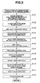
- step S101 an engine speed Ne, fuel injection quantity Qf and target intake air quantity tQac are read.
- step S102 by using, for example, a map shown in FIG. 8, a target EGR ratio MEGR is calculated
- step S103 the basic working medium ratio tQh0_qacb is calculated from a target intake air quantity tQac and an exhaust gas quantity VCE# per one cylinder in the following manner.
- tQh0_qacb tQac/(VCE# x ROU#)
- step S104 by using, for example, a map shown in FIG. 10, a dynamic time constant equivalent value td used for a delay process of a working medium ratio tQh0.
- step S106 the working medium correction coefficient tQh0_nhos that was calculated in step S104 is treated by a delay process by using the dynamic time constant equivalent value td.
- a target working medium ratio tQh0 is calculated by dividing the basic working medium ratio tQh0_qacb that was calculated in step S103 by the working medium correction coefficient tQh0_nhos that was calculated and treated by the delay process in step S106.
- step S108 by using, for example, a table shown in FIG. 11, an intake throttle opening area equivalent value tADNV per a unit engine rotation and a unit displacement is calculated from the target working medium ratio tQh0 that was calculated in step S107.
- tAtvob tADNV x Ne x VOL#
- step S110 by using, for example, a table shown in FIG. 12, an intake throttle valve opening area correction coefficient tAtvo_hos is calculated from the target EGR ratio MEGR.
- a final target intake throttle valve opening area tAtvo is calculated by multiplying the basic opening area tAtvob that was calculated in step S109 by the opening area correction coefficient tAtvo_hos that was calculated in step S110 in the following manner.
- tAtvo tAtvob x tAtvo_hos
- step S112 by using, for example, an opening area-opening degree conversion table shown in FIG. 13, a throttle valve target opening degree TVO is calculated.
- Intake throttle valve 8 is controlled so as to attain the target opening degree TVO.
- the intake throttle valve opening degree is corrected in response to a variation of the EGR ratio, thereby enabling the intake air quantity to become equal to the target value.
- the intake air control system of the present invention comprises a calculating means (constituted by control unit 20, the flowchart in FIG. 2, and maps and tables in FIGS. 8 to 13) for calculating a target opening area of the intake throttle valve 8 based on a target EGR ratio corresponding to the operating condition of the engine 1, and a control means (constituted by control unit 20) for controlling an opening degree of the intake throttle valve 8 based on the target opening area.
- the intake air control system of the present invention comprises the control unit 20 that controls the intake throttle valve 8 and the EGR valve 10 in accordance with an operating condition of the engine.
- the control unit 20 includes a target opening area calculating section (i.e., flowchart in FIG. 2 and maps and tables in FIGS.
- the EGR ratio has an influence on the pressure differential across the intake throttle valve. Namely, the intake air quantity varies depending upon a variation of the EGR ratio if the opening degree of the intake throttle valve 8 is the same.
- the excess air factor can be controlled so as to become equal to a target value.
- the larger the target EGR ratio becomes the larger target opening area results.
- the larger the EGR ratio the larger the EGR quantity flowing into an intake system portion downstream of the intake throttle valve becomes, thereby reducing the pressure differential across the intake throttle valve.
- the target opening area increases at a rate that increases with increase of the target EGR ratio.
- a resulting variation of the intake air quantity when the target EGR ratio is larger is smaller than that when the target EGR ratio is smaller (the opening area of the EGR valve is smaller) since the pressure differential across the intake throttle valve is smaller when the target EGR ratio is larger.
- the target opening area calculating section comprises a basic opening area calculating section (S101 to S109 of FIG. 2) that calculates a basic opening area of the intake throttle valve 8 based on a target intake air quantity corresponding to the operating condition of the engine 1, and an opening area correction coefficient calculating section (S110 and S111 of FIG. 2) that calculates an opening area correction coefficient based on the target EGR ratio corresponding to the operating condition of the enginel, the target opening area being the result obtained by multiplying the basic opening area by the opening area correction coefficient.
- a basic opening area calculating section S101 to S109 of FIG. 2 that calculates a basic opening area of the intake throttle valve 8 based on a target intake air quantity corresponding to the operating condition of the engine 1, and an opening area correction coefficient calculating section (S110 and S111 of FIG. 2) that calculates an opening area correction coefficient based on the target EGR ratio corresponding to the operating condition of the enginel, the target opening area being the result obtained by multiplying the basic opening area by the opening area correction coefficient.
- the basic opening area of the intake throttle valve 8 that can attain the target intake air quantity without consideration of the EGR ratio, i.e., in case EGR is not performed is first calculated, and then the basic opening area is corrected by the opening area correction coefficient that is calculated based on the target EGR ratio, in consideration of the influence of the EGR ratio.
- the basic opening area calculating section comprises a basic working medium ratio calculating section (S103 of FIG. 2) that calculates a basic working medium ratio that is the result obtained by dividing the target intake air quantity by a maximum intake air quantity at the time the intake throttle valve 8 is fully open, and calculates the basic opening area based on the basic working medium ratio.
- the intake air quantity caused by the same opening degree of the intake throttle valve (including the maximum intake air quantity corresponding to the maximum opening degree) varies depending upon a variation of the operating condition of the engine 1.
- an accurate basic opening area cannot be obtained directly from the target intake air quantity.
- the basic opening area in contrast to this, by determining the basic opening area so that the same basic working medium ratio is obtained, the working medium ratio being the ratio of the target intake air quantity to the maximum intake air quantity, an accurate target intake air quantity can be obtained even in case a different intake air quantity is caused by the same opening degree of the intake throttle valve (under the condition where EGR is not performed).
- the basic opening area can be calculated highly accurately.
- the basic opening area calculating section comprises a working medium ratio correction coefficient calculating section (S104 to S106 of FIG. 2) that calculates a working medium correction coefficient based on an engine speed, and calculates the basic opening area based on the basic working medium ratio and the working medium ratio correction coefficient.
- the maximum intake air quantity varies depending upon a variation of the engine speed.
- the working medium ratio correction coefficient calculating section comprises a delay process section (S105 and S106 of FIG. 2) that treats the working medium correction coefficient.
- a variation of the engine speed (at transitional operation of the engine) causes a delay or lag in attainment of the maximum intake air quantity.
- a working medium correction coefficient that is determined in consideration of the delay in attainment of the maximum intake air quantity at transitional operation of the engine can be obtained, thus making it possible to control the intake air quantity at transitional operation of the engine highly accurately.
- the working medium ratio correction coefficient calculating section calculates a time constant of the delay process section based on the engine speed and a fuel injection quantity.
- a delay in attainment of the intake air quantity varies (i.e., time constant varies) depending upon a variation of the operating condition of the engine 1.
- a value equivalent to an intake pressure downstream of the intake throttle valve is used as the basic working medium ratio.
- the basic working medium ratio there is a correlation between the intake pressure downstream of the intake throttle valve and the working medium ratio. Since the working medium ratio equivalent value can be detected from the intake pressure by using an intake pressure sensor, the basic working medium ratio can be calculated with ease. Further, a variation of the working medium ratio due to a variation of the maximum intake air quantity that is caused by deterioration with age can be compensated for.
- the basic working medium ratio tQh0_qacb can be calculated so as to be equated to an intake pressure detected by intake pressure sensor 22 that is disposed downstream of intake throttle valve 8 as indicated by one-dot chain line in FIG. 1.
- the scope of the invention is defined with reference to the following claims.
Landscapes
- Engineering & Computer Science (AREA)
- Chemical & Material Sciences (AREA)
- Combustion & Propulsion (AREA)
- Mechanical Engineering (AREA)
- General Engineering & Computer Science (AREA)
- Output Control And Ontrol Of Special Type Engine (AREA)
- Combined Controls Of Internal Combustion Engines (AREA)
- Exhaust-Gas Circulating Devices (AREA)
- Control Of Throttle Valves Provided In The Intake System Or In The Exhaust System (AREA)
- Electrical Control Of Air Or Fuel Supplied To Internal-Combustion Engine (AREA)
Applications Claiming Priority (2)
| Application Number | Priority Date | Filing Date | Title |
|---|---|---|---|
| JP2002095885A JP2003293796A (ja) | 2002-03-29 | 2002-03-29 | 内燃機関の吸気制御装置 |
| JP2002095885 | 2002-03-29 |
Publications (1)
| Publication Number | Publication Date |
|---|---|
| EP1348855A2 true EP1348855A2 (de) | 2003-10-01 |
Family
ID=27800555
Family Applications (1)
| Application Number | Title | Priority Date | Filing Date |
|---|---|---|---|
| EP03007133A Withdrawn EP1348855A2 (de) | 2002-03-29 | 2003-03-28 | Ansaugluftsteuervorrichtung und -verfahren für eine Brennkraftmaschine |
Country Status (3)
| Country | Link |
|---|---|
| US (1) | US6816771B2 (de) |
| EP (1) | EP1348855A2 (de) |
| JP (1) | JP2003293796A (de) |
Families Citing this family (15)
| Publication number | Priority date | Publication date | Assignee | Title |
|---|---|---|---|---|
| SE524706C2 (sv) * | 2002-06-03 | 2004-09-21 | Stt Emtec Ab | Anordning och förfarande för rening av avgaser samt användning av anordningen vid en diselmotor |
| JP4126560B2 (ja) * | 2004-09-15 | 2008-07-30 | トヨタ自動車株式会社 | 内燃機関の制御装置 |
| JP4222308B2 (ja) * | 2005-01-11 | 2009-02-12 | トヨタ自動車株式会社 | 内燃機関の空気量推定装置 |
| US20070068141A1 (en) * | 2005-06-15 | 2007-03-29 | Opris Cornelius N | Exhaust treatment system |
| US7107764B1 (en) | 2005-06-15 | 2006-09-19 | Caterpillar Inc. | Exhaust treatment system |
| US7762060B2 (en) | 2006-04-28 | 2010-07-27 | Caterpillar Inc. | Exhaust treatment system |
| US20080078170A1 (en) * | 2006-09-29 | 2008-04-03 | Gehrke Christopher R | Managing temperature in an exhaust treatment system |
| US7433775B2 (en) * | 2006-11-17 | 2008-10-07 | Gm Global Technology Operations, Inc. | Engine torque control at high pressure ratio |
| EP2117079B1 (de) * | 2008-05-08 | 2019-05-08 | BlackBerry Limited | Mobile drahtlose Kommunikationsvorrichtung mit selektiver Antennenlastschaltung für Antennen und entsprechende Verfahren |
| JP5277349B2 (ja) * | 2010-04-23 | 2013-08-28 | 本田技研工業株式会社 | 内燃機関の吸気パラメータ算出装置および吸気パラメータ算出方法 |
| JP5589987B2 (ja) * | 2011-07-26 | 2014-09-17 | 三菱自動車工業株式会社 | 排気温度制御装置 |
| US9677510B2 (en) * | 2014-10-14 | 2017-06-13 | Ford Global Technologies, Llc | Systems and methods for transient control |
| CN111412071B (zh) * | 2020-02-20 | 2022-07-15 | 义乌吉利动力总成有限公司 | 一种egr率的计算方法、装置、车载终端及储存介质 |
| CN111502840B (zh) * | 2020-03-31 | 2022-07-15 | 义乌吉利动力总成有限公司 | 一种导气管出口egr率的计算方法及装置 |
| CN119353112B (zh) * | 2024-10-17 | 2025-09-30 | 东风汽车集团股份有限公司 | 一种混合阀开度请求控制方法 |
Family Cites Families (5)
| Publication number | Priority date | Publication date | Assignee | Title |
|---|---|---|---|---|
| JPS6193237A (ja) | 1984-10-11 | 1986-05-12 | Mazda Motor Corp | エンジンのスロツトル弁制御装置 |
| JP3546703B2 (ja) * | 1998-06-26 | 2004-07-28 | トヨタ自動車株式会社 | 内燃機関のアクチュエータ制御装置 |
| JP3630060B2 (ja) * | 1999-06-30 | 2005-03-16 | トヨタ自動車株式会社 | 燃焼式ヒータを有する内燃機関 |
| JP3649171B2 (ja) * | 2001-08-22 | 2005-05-18 | トヨタ自動車株式会社 | 内燃機関の制御装置 |
| JP3997477B2 (ja) * | 2001-10-05 | 2007-10-24 | 株式会社デンソー | 内燃機関の制御装置 |
-
2002
- 2002-03-29 JP JP2002095885A patent/JP2003293796A/ja active Pending
-
2003
- 2003-03-21 US US10/392,908 patent/US6816771B2/en not_active Expired - Fee Related
- 2003-03-28 EP EP03007133A patent/EP1348855A2/de not_active Withdrawn
Also Published As
| Publication number | Publication date |
|---|---|
| US20030188712A1 (en) | 2003-10-09 |
| US6816771B2 (en) | 2004-11-09 |
| JP2003293796A (ja) | 2003-10-15 |
Similar Documents
| Publication | Publication Date | Title |
|---|---|---|
| US7801669B2 (en) | Exhaust gas control system for internal combustion engine | |
| US8630787B2 (en) | Controlling exhaust gas recirculation in a turbocharged engine system | |
| CN101779025B (zh) | 用于内燃机的排气再循环设备以及排气再循环流量推定方法 | |
| US8091350B2 (en) | Exhaust purification apparatus for engine | |
| US6816771B2 (en) | Intake air control system and method for an internal combustion engine | |
| JP4111094B2 (ja) | 排気後処理装置付過給エンジンの制御装置および制御方法 | |
| US7665297B2 (en) | Exhaust purifying apparatus for internal combustion engine | |
| CN100360781C (zh) | 废气清除设备 | |
| JP5136654B2 (ja) | 内燃機関の制御装置 | |
| JP4466008B2 (ja) | エンジンの燃料噴射制御装置 | |
| US7275363B2 (en) | Exhaust gas purifying apparatus and method for internal combustion engine | |
| US7742866B2 (en) | Fuel volatility compensation for engine cold start speed control | |
| EP1306538A2 (de) | Vorrichtung und Verfahren zur Steuerung einer Brennkraftmaschine | |
| US20150083095A1 (en) | Internal combustion engine and control method therefor | |
| US7198030B2 (en) | Internal combustion engine | |
| JP4973370B2 (ja) | 内燃機関の排気浄化装置 | |
| EP1536121A1 (de) | Regelungssystem eines Katalysators einer Brennkraftmaschine und Verfahren zur Regelung des Katalysators | |
| JP5608614B2 (ja) | エンジンのegr流量検出装置 | |
| EP1536120A2 (de) | Abgassteuerungsvorrichtung und -methode für eine Brennkraftmaschine | |
| JP3925273B2 (ja) | 内燃機関の排気浄化装置 | |
| JP2020041435A (ja) | 排気再循環装置の動作制御方法及び排気再循環装置 | |
| JP2009167836A (ja) | 内燃機関の燃料噴射制御装置 | |
| EP1683953A1 (de) | Steuervorrichtung für einer Brennkraftmaschine | |
| JP2008038625A (ja) | 内燃機関の排気浄化装置、及び方法 | |
| JP2008291811A (ja) | セタン価推定装置及び方法 |
Legal Events
| Date | Code | Title | Description |
|---|---|---|---|
| PUAI | Public reference made under article 153(3) epc to a published international application that has entered the european phase |
Free format text: ORIGINAL CODE: 0009012 |
|
| 17P | Request for examination filed |
Effective date: 20030328 |
|
| AK | Designated contracting states |
Kind code of ref document: A2 Designated state(s): AT BE BG CH CY CZ DE DK EE ES FI FR GB GR HU IE IT LI LU MC NL PT RO SE SI SK TR |
|
| AX | Request for extension of the european patent |
Extension state: AL LT LV MK |
|
| STAA | Information on the status of an ep patent application or granted ep patent |
Free format text: STATUS: THE APPLICATION HAS BEEN WITHDRAWN |
|
| 18W | Application withdrawn |
Effective date: 20070112 |