EP1347713B1 - Verfahren für eine protheseninstallation - Google Patents
Verfahren für eine protheseninstallation Download PDFInfo
- Publication number
- EP1347713B1 EP1347713B1 EP01272996A EP01272996A EP1347713B1 EP 1347713 B1 EP1347713 B1 EP 1347713B1 EP 01272996 A EP01272996 A EP 01272996A EP 01272996 A EP01272996 A EP 01272996A EP 1347713 B1 EP1347713 B1 EP 1347713B1
- Authority
- EP
- European Patent Office
- Prior art keywords
- party
- model
- dental
- jaw
- fixtures
- Prior art date
- Legal status (The legal status is an assumption and is not a legal conclusion. Google has not performed a legal analysis and makes no representation as to the accuracy of the status listed.)
- Expired - Lifetime
Links
Images



Classifications
-
- A—HUMAN NECESSITIES
- A61—MEDICAL OR VETERINARY SCIENCE; HYGIENE
- A61C—DENTISTRY; APPARATUS OR METHODS FOR ORAL OR DENTAL HYGIENE
- A61C13/00—Dental prostheses; Making same
- A61C13/0003—Making bridge-work, inlays, implants or the like
- A61C13/0004—Computer-assisted sizing or machining of dental prostheses
-
- A—HUMAN NECESSITIES
- A61—MEDICAL OR VETERINARY SCIENCE; HYGIENE
- A61C—DENTISTRY; APPARATUS OR METHODS FOR ORAL OR DENTAL HYGIENE
- A61C1/00—Dental machines for boring or cutting ; General features of dental machines or apparatus, e.g. hand-piece design
- A61C1/08—Machine parts specially adapted for dentistry
- A61C1/082—Positioning or guiding, e.g. of drills
- A61C1/084—Positioning or guiding, e.g. of drills of implanting tools
-
- B—PERFORMING OPERATIONS; TRANSPORTING
- B33—ADDITIVE MANUFACTURING TECHNOLOGY
- B33Y—ADDITIVE MANUFACTURING, i.e. MANUFACTURING OF THREE-DIMENSIONAL [3D] OBJECTS BY ADDITIVE DEPOSITION, ADDITIVE AGGLOMERATION OR ADDITIVE LAYERING, e.g. BY 3D PRINTING, STEREOLITHOGRAPHY OR SELECTIVE LASER SINTERING
- B33Y80/00—Products made by additive manufacturing
-
- G—PHYSICS
- G06—COMPUTING OR CALCULATING; COUNTING
- G06Q—INFORMATION AND COMMUNICATION TECHNOLOGY [ICT] SPECIALLY ADAPTED FOR ADMINISTRATIVE, COMMERCIAL, FINANCIAL, MANAGERIAL OR SUPERVISORY PURPOSES; SYSTEMS OR METHODS SPECIALLY ADAPTED FOR ADMINISTRATIVE, COMMERCIAL, FINANCIAL, MANAGERIAL OR SUPERVISORY PURPOSES, NOT OTHERWISE PROVIDED FOR
- G06Q10/00—Administration; Management
- G06Q10/10—Office automation; Time management
- G06Q10/103—Workflow collaboration or project management
-
- A—HUMAN NECESSITIES
- A61—MEDICAL OR VETERINARY SCIENCE; HYGIENE
- A61C—DENTISTRY; APPARATUS OR METHODS FOR ORAL OR DENTAL HYGIENE
- A61C13/00—Dental prostheses; Making same
- A61C13/225—Fastening prostheses in the mouth
- A61C13/26—Dentures without palates; Partial dentures, e.g. bridges
Definitions
- the present invention relates to a method for producing an assembly template and tooth replacement as claimed in claim 1. Also disclosed is a method for allocating prosthetic installation work between at least three parties, where a dental situation and fixture applications therein are simulated on a computer screen (in computer equipment) by the first party, first components in connection with the prosthetic installation are produced by the second party with the aid of a recording and said simulation, second components are supplied by the third party, and the prosthetic installation is assembled and fitted by the first party by means of said first and second components.
- An arrangement connected with this method is also disclosed.
- a method for replacing, in a short application time, a loose prosthesis with a fixed installation in a completely or partially edentulous patient is also described.
- a short application time is understood, for example, to be a time of 1 to 4 hours, for example ca. 11 ⁇ 2 to 2 hours.
- the arrangement is intended for applying fixed installations, for example in the form of dental bridges, in patients who are completely or partially edentulous, at least in one jaw bone, preferably the upper jaw bone.
- the arrangement can comprise first units (or items of equipment) with the task of determining measures in the various patient cases, dealing with the production of computerized representations with fitted fixture applications in the various cases, producing working models of the desired installations and opposite jaw bone, ordering the production of dental bridges and fixtures and securing members for securing the dental bridges, and effecting the application of the fixtures and the securing of the installations or dental bridges in the patients' jaw bones.
- Said first units or items of equipment are related to dentists, dental specialists, prosthetists, surgeons, clinics or hospitals for X-ray tomography, etc.
- Second units or items of equipment which represent or are located at dental technicians or the like use information relating to the computerized representations and the working models to produce templates for forming fixture holes on the patients and the patients' dental bridges.
- a third unit or item of equipment which represents a supplier of basic elements and/or structural parts (cf. PROCERA) receives from the first units or items of equipment, via ordering and distribution channels, the order for fixtures and accessories which are necessary for executing the various orders for different patients.
- the ordering and distribution channels can comprise or consist of telecommunication and/or computer links, it being possible for the Internet to form or be part of one or more links.
- the arrangement can thus permit, within said short time, the application of a prosthetic installation by means of structural parts, dental crowns, dental bridges, etc., received from a second party who can include said dental technicians, and components, for example implants, spacers, securing screws, etc., received from a third party, who can be a producer of basic elements and structural parts.
- the structural parts can be extracted with production parts which can consist of models, templates, impressions, readings, tools, etc., and equipment or items of equipment for complete or partial production of the production parts, which equipment or items of equipment are owned by or available to at least the third party, which signifies that in an alternative embodiment the third party is able in turn to arrange the production to be done by a further party specialized in the particular production part or production parts.
- the arrangement can thus permit, with considerable precision requirements, the securing of a particular dental installation in a jaw bone or other bone of a patient by means of fixtures and securing members.
- the arrangement can in this case comprise or operate with first equipment for imaging the jaw bone and possible prosthesis, second equipment for reproducing representations of the jaw bone and possible prosthesis in computer equipment, said computer equipment being intended to permit virtual or planned fixture application in the representation.
- the arrangement also comprises or operates with third equipment for producing an installation part based on the representation, and fourth equipment for producing working models, by means of which attachments can be made on the installation part and the latter can be finished.
- the disclosure also relates to an arrangement which permits a responding party to supply to an inquiring party or parties information which may concern the prosthetic installation and the work associated with the latter.
- a computer is in this case designed to simulate a dental situation and fixture applications therein.
- One or more production units are arranged to produce components intended for the prosthetic installation and for fitting the latter, and equipment located at the respective inquiring party is designed to permit or prepare the prosthetic installation.
- the arrangement is intended to permit the supply of components or products for prosthetic installations and the design of these from the producing party to the party ordering the components.
- the supply is in this case based on the handling of orders, finances, invoices, the components or the products and the ordering parties, i.e. the customers.
- the disclosure also proposes a program stored on a computer medium for generating a protocol with the aid of one or more computers for production, fitting and/or monitoring of the production and fitting of dental prosthetic installations.
- One party or unit in this case supplies components or products for the prosthetic installations and the designs of these.
- the parties or units ordering said components or products prepare and install the prosthetic installations.
- the third party (who in some of the subsequent arrangements of the parties has also been referred to as the second party in the chain, and this for technical reasons) must be able to ensure efficient and accurate distribution and debiting of the basic elements, parts and services involved.
- the second party (who for technical reasons can also be referred to as the third party in certain cooperation formats) must be able to perform his part of the work and satisfy the precision requirements which have been set.
- the first party must, as previously, be responsible for diagnostics and produce images and models of the patient and carry out the final installation work in a very short time.
- the debiting and mutual allocation of the resources provided must in this case be able to be done in accordance with what is proposed.
- the recording includes a first reading of an impression or prosthesis (tooth structure) and a second reading of a portion (all or part of a jaw) supporting the prosthetic installation, that the simulation includes collation of images or representations on the computer screen, which images or representations result from the first and second readings and on the basis of which the simulated fixture applications are constructed, and that the simulated fixture applications include chosen positionings in relation to said supporting portion.
- the method is further characterized by the fact that a model, for example made of plastic, is produced, preferably by a stereolithography method, by one of said parties, or a fourth party, and that the first components include an assembly template which can be applied to said substrate and is produced by means of the model and is intended for hole-forming members which are guided by the assembly template in the substrate in directions which correspond to the directions of the chosen positionings.
- the method can be considered as being characterized by the fact that the first components include a unit forming part of the installation, for example a dental crown, which is provided with attachment holes which connect to the holes formed in the substrate, that the second components include the fixtures which are applied in said formed holes by the first party, and that the second components also include securing members, for example securing screws, for securing the unit in said applied fixtures.
- the first components include a unit forming part of the installation, for example a dental crown, which is provided with attachment holes which connect to the holes formed in the substrate
- the second components include the fixtures which are applied in said formed holes by the first party, and that the second components also include securing members, for example securing screws, for securing the unit in said applied fixtures.
- the recording includes a first reading of an impression or prosthesis (tooth structure) and a second reading of a portion (all or part of a jaw) supporting the prosthetic installation
- the computer i.e. its program
- the computer is intended, in connection with the simulation, to permit collation of images or representations on the computer screen, which images or representations result from the first and second readings, and to indicate on these the simulated fixture applications which include chosen positionings in relation to said supporting portion, and that second equipment, preferably stereolithography equipment, which is located with one of the parties, or with a fourth party, is intended for production of a model, for example of plastic.
- the first production unit is provided for production of an assembly template which has been constructed by means of the model and which has guide elements for hole-forming members which can be guided by the assembly template in order to assume directions which correspond to the directions of the chosen positionings, and that the first production unit is also provided for production of a structural unit or structural part, for example a dental crown, which forms part of the installation and which is provided with attachment holes which connect to the holes formed in the substrate.
- the second production or supply unit produces or supplies the fixtures intended for said formed holes, and also securing members (for example, screws) for securing the structural unit in the fixtures which are applied in the substrate.
- a first step includes control, for example primary radiography, of the jaw-bone status by the first party who in this case can be a dentist, dental specialist, prosthetist, etc. If the status is acceptable, X-ray tomography is performed by a surgeon, hospital, clinic, who or which have access to the radiography equipment in question.
- a simulated first representation of the X-ray tomography is input into the computer equipment, preferably by the first party.
- a simulated second representation of a scanning or reading of a loose prosthesis is additionally input into said computer equipment, which scanning or reading can be carried out by the first party or second party.
- the first and second representations are coordinated in the computer equipment, in connection with which virtual fixtures are placed in position by the first party, who in this case can be a dentist, prosthetist, dental expert, etc.
- the result thus obtained is transferred, preferably via the telecommunications and/or computer network, which can include the Internet, to a second party who in this case is a producer of dental basic elements and structural parts (cf. PROCERA) in the form of computer information or digital information which can be related to the first and second representations, said coordination and said virtual fixtures.
- a producer of dental basic elements and structural parts cf. PROCERA
- model can be a plastic model of the first and second representations, this being done by the second party who owns or has access to stereolithography equipment.
- Elements are introduced into the actual model, for example tubular elements which extend and are placed in positions and directions corresponding to the positions and directions for the virtual fixtures.
- the actual model is thereafter transferred to a third party who in this case is a dental technician or the dental laboratory.
- a loose prosthesis model, preferably made of wax, is also transferred to the third party, preferably from the first party, together with a jaw model of the opposite jaw, which last-mentioned model can be made of plaster.
- a bite register index is transferred to the third party, i.e. the dental technician.
- the third party (the dental technician) uses an articulator in order to produce the patient's bite configuration by means of said loose prosthesis and jaw models and bite register index, taking into consideration the soft-tissue space between jaw bone and teeth.
- the third part (the dental technician) uses the jaw model to produce an assembly template with a defined position of application to or in relation to the jaw model and thus in relation to the patient's jaw and with identified directions and positions for fixture dummies and thereby for the planned recesses in the patient's jaw bone.
- the assembly template and the produced tooth replacement or dental bridge are transferred to the first party (dentist, prosthetist, surgeon, etc.) who, by means of the assembly template, forms holes for the planned fixture insertions and, after insertion of the fixtures in the holes, anchors the dental bridge to the fixtures thus inserted.
- the supplier of basic elements and structural parts supplies basic sets of elements, which can consist of fixtures, securing screws, tools, etc., to the first units which are dentists, dental specialists, prosthetists, etc., as a function of first orders.
- the basic sets can in this case cover the different variations which can arise in the particular dental situations which can consist of applying dental bridges to completely or partially edentulous patients.
- the last-mentioned supplier of basic elements and structural parts (PROCERA) supplies accessory elements belonging to the basic sets, which accessory elements make it possible to deal with differences in the jaw-bone status and jaw-bone sizes of patients. In other words, as is known per se, the patients have jaw bones of different sizes and structures and for this reason said accessory elements to the basic set are required in order to permit effective treatment by the dentist, prosthetist or the like.
- the producer of basic elements and structural parts or the third party owns, or has available to it, equipment designed to operate with an ordering function in which the equipment receives, via a telecommunications and/or computer link, for example including the Internet in accordance with the above, information relating to a dental situation with jaw-bone structure simulated on computer by the first party, a model of the installation applied to this, and fixtures (implants) applied in the jaw-bone structure and belonging to the abovementioned components, and in addition the equipment belonging to the producer of basic elements and structural parts is designed to operate with stereolithographic production of an actual model, for example made of plastic, of said simulated jaw-bone structure and simulated model, which actual model is included in said production parts.
- a telecommunications and/or computer link for example including the Internet in accordance with the above, information relating to a dental situation with jaw-bone structure simulated on computer by the first party, a model of the installation applied to this, and fixtures (implants) applied in the jaw-bone structure and belonging to the abovementioned
- the components and optional production parts held by the third party can in this case be arranged in platforms which are adapted in dimensions to different sizes in different dental situations (i.e. greater or lesser widths, heights, etc., of the jaw bone and installations in question).
- treatment arrays for different situations can be offered.
- the basic arrays can be presented in different platform situations, where a first platform relates to the dimensions "wide”, “regular” and “narrow", which thus relate to the jaw-bone structures.
- first equipment is designed for imaging the jaw bone and any prosthesis
- second equipment for reproducing a representation of the jaw bone and the possible prosthesis in the computer equipment, said computer equipment being designed to permit virtual fixture application in the representation
- third equipment for producing an installation part based on the representation
- fourth equipment for producing working models by means of which attachments can be effected on the installation part and the latter can be finished.
- the arrangement in question preferably the fourth equipment, is designed to produce hole-forming templates which can be applied with precision to the jaw bone, and the items of equipment operate with an accuracy which satisfies said considerable precision requirements and eliminates the need for carrying out sample trials on the patient between the stages of imaging and hole formation, all this with the aim of achieving a short time for securing the installation, which short time can be, for example, 1 to 3 hours, during which holes are formed and fixtures applied and the installation is secured in the implanted fixtures.
- the storage arrangement will be of modular design with a substantially identical or corresponding structure for each module.
- the modules can be expanded or reduced on the basis of the number of new customers or departing customers. Alternatively, the customer clientele may change character and/or be redistributed.
- a data-processing arrangement can contain or receive data or information relating to selected parameters of installations previously produced in the practice.
- the data-processing arrangement can be designed to receive and compare one or preferably several parameters of the current prosthetic installation with a corresponding parameter or corresponding parameters of said selected parameters.
- Said information can represent the result of the particular comparison and can, for example, relate to one or more properties of the prosthetic installation, for example strength, esthetic appearance and/or color.
- the information can consist of or comprise details and/or data to the effect that the prosthetic installation conceived of by the inquiring party and/or the associated work on this installation is within a risk zone and unacceptable.
- a program is provided which is stored on a computer medium for generating a protocol with the aid of one or more computers in the production, fitting and/or monitoring of the production and fitting of dental prosthetic installations, where a party or unit supplies components or products for the prosthetic installations and the design of these, and where ordering parties or units-who ordered said components or products prepare and insert the prosthetic installations.
- the features which can principally be regarded as characterizing the program are the stages comprising: definition of patient and his/her tooth and/or jaw-bone status, definition of work procedure for the patient based on production and comparison with stored data relating to similar or corresponding prosthetic installations; definition of the advantages with the current prosthetic installation; definition of models, for example drill model; definition of X-ray tomography; definition of two-dimensional or three-dimensional CADD equipment; definition of model production by means of stereolithography; definition of model production by dental technicians; and definition of preparations by surgeon.
- the definitions in question take place in parallel with production of definitions of variables, documents, forms, folders and/or envelopes.
- the work time on patients is surprisingly shortened.
- the patient can already leave the dentist, prosthetist, surgeon, etc., with a fixed installation applied in his jaw.
- the fixed installation can incorporate effectively without too much inconvenience to the patient, who thereby avoids a protracted process involving insertion of fixtures and tests being done on these, which tests have hitherto comprised a number of trials.
- the precision requirements can be built-in with the second and third parties, i.e. the dental technician or the dental laboratory and the supplier of the basic elements and structural sets (cf. PROCERA).
- Computer programs for producing the models in question with very great precision are available on the market and can be used in this context.
- Said exact models can be used as structural models by the dental technician or the dental laboratory, which receives guarantees of the required precision in connection with dental installations.
- the invention also affords refined treatment methods in connection with the production of models, templates, etc., and also structural parts and installations which are to be used by the dental technician, prosthetist, dental expert, surgeon, etc.
- algorithms can be developed for calculation and computer programming in order to collate and handle different data parameters for example characterized by form and installations of a large number of preparations.
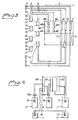
- a patient is symbolized by P and three parties by A, B and C, a first party being a dentist, prosthetist, dental expert, surgeon, etc., i.e. the party or subsidiary party dealing with the diagnosis and actual installation work on the respective patient.
- a second party B is represented by the dental technician or the dental laboratory
- a third party C is a supplier of basic elements and structural parts (cf. PROCERA).
- the third party has access to automated production of the basic elements and structural parts in question.
- the equipment or units located with the first party are symbolized by 1
- the equipment and units located with the second party are symbolized by 2
- the equipment and units located with the third party are symbolized by 3.
- the distribution between the various functions is utilized in a manner known per se by the patient P.
- the party A can be considered as having access to X-ray functions at a hospital, clinic or corresponding establishment 4.
- the third party C can own or have access (for example on a contract) to stereolithography equipment 5 of a type known per se.
- the first party A i.e. the actual subsidiary party
- the patients are completely or partially edentulous in the upper jaw, for which reason an examination of this jaw is most often carried out. It is possible per se to provide fixed installations in a lower jaw which is missing one or more teeth. In a case where it is decided that the patient is able to receive a fixed installation, the patient's jaw or jaw part must be read off or scanned. In addition, imaging of any loose prosthesis (tooth prosthesis) must be carried out. In the present case, the imaging function is indicated in Figure 1 by means of arrows 6 and 7, where the first arrow represents the imaging of the jaw or jaw part, and the arrow 7 represents the imaging of any loose prosthesis.
- a digital signal 11 is transmitted by the party A to the party C who imports or receives the signal 11 in computer equipment 3a.
- the transmission is made via a link 12 in the direction of the arrow 13.
- the digital signal 11 represents representations of the patient's jaw bone and loose prosthesis or equivalent.
- the signal 11 also represents a coordination of the imaged jaw bone and the imaged loose prosthesis and also fixture applications which have been made by the party A in a manner known per se.
- the link 12 can be made via telecommunication and/or computer links, which can include the Internet.
- the expression telecommunication and/or computer links can be taken to mean the generally available links or special links.
- the party C contacts a fourth party (not shown in Figure 1 ) if the third party C does not itself have the stereolithography equipment in question.
- the fourth party in this case owns the equipment in question, and the third party transfers information 12 concerning the order and information which corresponds to the readings taken by the first party A.
- the information 14 is digitalized and transmitted via telecommunication and/or computer links in accordance with the above.
- the direction of the signal is indicated in Figure 1 by the arrow 15.
- the fourth party designs or produces the stereolithographic wax model and sends the latter back to the third party see the arrow 16.
- Debiting functions and ordering functions take place via said link 17, and the debiting functions known per se are in this case used at or by the party C.
- the computer equipment located with the fourth party is indicated by 5a.
- Information regarding the plastic model produced is sent back if appropriate to the first party A in the direction of the arrow 18.
- the stereolithographic actual model is transferred from the party C to the party B, see arrow 19.
- the second party receives, from the first party, orders to the effect that the model in question is to be produced. This ordering can be done via the telecommunication and/or computer network and has been symbolized in Figure 1 by the digital signal 20.
- information 21 concerning planned treatment, individual characteristics, date, cost, etc. is transmitted to the second party B which has access to computer equipment 2a.
- the first party A also orders from the third party' C basic arrays for the given patient type and possible auxiliary arrays which are intended to meet special characteristics of the patient.
- Said arrays comprise different types of basic elements, for example drills/fixtures, drill guides, guide drills and other types of drills, recessing members, fixtures, mounting spacers, screw tighteners, supports, support pins, devices, toothbrushes, cement sets, millers and machines for bite grinding and means for blocking holes, etc.
- the ordering and debiting functions are effected in the third party's known ordering and debiting equipment.
- the ordering function is digitalized and is represented by 22 in Figure 1 .
- the distribution path can also be considered as part of the link 12 in the direction of the arrow 18.
- Corresponding ordering, distribution and debiting channels are established between the second party B and the third party C.
- the ordering from the second party is digitalized, in the same way as above, and takes place with digital signals 23 in the direction of the arrow 24.
- Supplies and debiting functions from the party C to the party B take place via the link 25 in the direction of the arrow 19 by means of digital information 26 and a hardware distribution channel which can .be considered as forming part of, or is symbolized by, the link 25.
- the second party produces, as final products, first components which are supplied to the first party via distribution channel 27, indicated symbolically in Figure 1 , in the direction of the arrow 28.
- Said first components comprise an assembly template 29 which the first party uses as a hole-forming member.
- a unit forming the installation for example a dental crown 30.
- the third party supplies second components 31 in accordance with the description given above and below.
- the first party uses the assembly template for forming holes in the patient's jaw and applies the fixtures which have been obtained from the third party and are included in said second components 31.
- the third party supplies, inter alia, the abovementioned securing screws to the first party.
- the first party can form holes, apply the fixtures and anchor the installation or the dental crown to them in the abovementioned very short time.
- subsidiary equipment 32 located with the first party B use is made, inter alia, of an articulator of a type known per se.
- a model, for example a plaster model 33, of the opposite jaw is applied in the articulator, together with the actual model produced by stereolithography, fixture dummies and said bite register index.
- soft plastic or the like is used to produce a model of the gum which will lie between the jaw-bone model and the loose prosthesis model, which is also produced by the first party.
- the second party produces the dental bridge with the aid of the stereolithographic plastic model, to which spacers are mounted on fixtures of the model and cementing sleeves are secured on the spacer.
- the frame of the dental bridge is preferably made of carbon fiber-reinforced plastic, but can also be made of titanium or a dental alloy.
- the soft-tissue replacement can be made of vinyl or polysiloxane. The lengths of the spacers and the configuration of the bridge with respect to soft tissues are determined and imaged. Prosthetic teeth are applied on the structural part or bridge skeleton thus formed.
- the tooth replacement or prosthetic teeth are worked for example from a wax model in which the prosthetic teeth are made of acrylate and have been tested on the patient.
- the soft tissue can be provided with small pin-shaped or spike-shaped elements which are automatically imaged in a computer program during the stereolithographic production.
- Said assembly template can comprise spacers which bear hole-forming sleeves or drill sleeves and are held together with the aid of said carbon fiber-reinforced plastic.
- a number of patients are indicated by P, P', P", P"'. These patients are assumed to turn to party A who carries out the abovementioned examination and modeling.
- the patients are handled by means of first equipment 34 and the first party, in accordance with the above, orders the basic sets 35, 36 and 37 and any relevant auxiliary sets 38, 39 and 40 in order to meet the type of dental treatment with its associated variations.
- the connections of the patients to the first party are indicated by 41, 42, 43 and 44.
- the distribution channels from the third unit or party C to the first unit or party A are indicated by 45, 46, 47, 48, 49 and 50.
- Other components for example structural parts, tools, instruments, can also be ordered by party A from party C and are symbolized by component content 51 and the distribution path 52.
- the wax model or a representation of the wax model can be distributed on this path.
- the party B can also place orders with the party C.
- Such orders can include models, tools, instruments, etc., and are symbolized by the component content 53 and the distribution paths 54 and 55, which for example can be parcel delivery routes.
- debiting functions or debiting equipment are indicated by 56 at the third party, by 57 at the second party and by 58 at the first party.
- Said debiting channels are established using coupled-up or fixed telecommunication and/or computer links, which also serve as the abovementioned ordering and data signal transfer channels.
- the party A can order equipment or a model from party C via the link 59, which is recorded by the party C and debited via the same or corresponding link.
- the ordering direction is indicated by 60 and the debiting direction and confirmation direction is indicated by 61.
- the party B can also place orders with the party C, and this is done via a link 62 in a direction indicated by 63. Debiting of the equipment or service in question can take place via a corresponding link 62 in the direction 64.
- ordering and debiting functions are exchanged between the units A and B via a link 65.
- a parcel link or hardware link 66 is also arranged between these units A and B in order to permit transfer of models from party A to party B and finished installations, templates, etc., from party B to party A.
- links 67 for the debiting of the patient by the party A are also indicated symbolically.
- a large number of patients P are served by a relatively large number of first parties (dentists, prosthetists, etc.).
- the first parties are served in turn by a number of dental technicians or laboratories which are assumed to be present in a smaller number than the number of first parties.
- a third unit C (PROCERA) can serve the whole number of patients and first and second units.
- the third unit supplies said basic arrays 68a, 68b, 68c and auxiliary sets 68a', 68b' and 68c' belonging to these.
- Components, instruments, etc. are symbolized by 69 and, in accordance with the above, can be supplied to the second party B, see indicated arrows.
- the third party can also offer a service, which has been indicated by 70, which service can be oriented toward the patients and said first and second parties.
- a service which has been indicated by 70, which service can be oriented toward the patients and said first and second parties.
- the principal debiting function is indicated by 71.
- the ordering functions received in the different areas are also shown by 72, 73 and 74.
- the arrows shown in Figure 3 indicate the directions of the services, components and debiting in the system.
- the computer equipment located with the parties A, B and C is indicated by 75, 76 and 77, respectively.
- the computer equipment for the X-ray function and for the stereolithography function is indicated by 78 and 79.
- the computer equipment is connected by modem, see for example 75a and 76a on computer equipment 75 and 76, to different networks.
- the electronic networks or the links can consist of the general communications network which in Figure 4 is symbolized by 80, one or more specially arranged, for example fixed, links 81 and/or computer network links 82 which can consist of or include the Internet.
- the computer equipment can be connected by the respective modems to one or more of said networks.
- the party B (the dental technician or the dental laboratory) requires a model which images the jaw bone and the dental prosthesis with an intermediates space between these, which intermediate space actually corresponds to the space for soft tissue (gum).
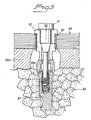
- the positions for the fixture installations are planned in advance. Around the holes, or for forming the holes, sleeves made of solid material are needed to secure the installation of the fixture in the plastic model. That part of the plastic model which images the jaw bone is seen in Figures 5 and 6 , where the jaw bone model has been indicated by 83 in Figure 5 .
- a soft-tissue imitation made of soft plastic is indicated by 84.
- the plastic model is obtained from the third party.
- a model or tooth replacement made of wax with prosthetic teeth made of acrylate is tested out in the patient's mouth and checked for the appropriate color, shape and articulation. This too is sent to the dental technician who produces the jaw-bone bridge in order to allow the acrylate teeth of the bridge to be transferred to the finished dental bridge.
- the party B receives a plaster model or an impression of the opposite jaw made of impression material which is not disturbed during transport to the dental technician.
- the bite register index can expediently be made of wax in order to permit registering of the jaws' bite relationship to each other.
- the second party will obtain a description of the order, the planned therapy, special requirements, for example individual characteristics and other details which concern the work, and the date when the work will be done at the clinic (at the party A).
- the first party will in accordance with the above be provided with prosthetic and surgical instruments in accordance with the above.
- a plastic model and dental bridge will be available, likewise the abovementioned basic sets and optional auxiliary sets.
- the plastic model is according to the above a model of the patient's jaw which has been imaged with the aid of computerized X-ray tomography. In order to permit bite registering and mounting in the articulator, it also includes the tooth replacement.
- the positions of the seats for the fixtures are determined in advance in accordance with the above, and the plastic model is then produced with the aid of stereolithography using an epoxy material in the present illustrative embodiment.
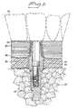
- the model images the jaw bone 83 and the dental prosthesis 85 (see Figure 6 ) with said intermediate spaces 86 for soft tissue.
- the dental prosthesis model is supported on the jaw-bone model 83 with the aid of pins (not shown) which are automatically imaged in the program upon production in the stereolithography process.
- Suitable fixtures 87 are placed in the planned holes/seats on the model.
- An assembly template 88 (see Figure 5 ) is produced with the aid of the model.
- the assembly template represents a template for drill/fixture RP.
- the holes are strengthened with sleeves 89, and the arrangement is also such that an expansion spacer 90 and an expansion screw 91 are included in order to hold the template in a defined ideal position, even during the actual tightening when the template is not allowed to tilt in its attachments.
- the spacer 90 bears against the fixture 87.
- said template can then be transferred to the patient and there functions as a hole-forming template which provides a high degree of precision.
- the latter is provided with support parts 88a which bear against the top surface 83a of the jaw model 83.
- the extent of the template in or along the entire extension of the jaw bone, with its irregularities, means that the template acquires a precise position in the patient's mouth.
- the template comprises carbon fiber-reinforced plastic.
- a dental bridge is produced from the plastic model part according to Figure 6 .
- Special spacers 92 which are intended to be used by the dental laboratory or by the dental technician are mounted on the fixtures 87 of the model and cementing sleeves 93 are applied on the spacers.
- the bridge skeleton 85 can consist of carbon fiber-reinforced plastic, titanium or some other dental alloy.
- the spacers are preferably made of titanium and in one embodiment have lengths of 3.5 and 5 mm.
- the spacers are intended to be cemented on the titanium sleeves 93 in the bridge in the patient's mouth and screwed tight to the fixtures using gold spacer screws 94. Tooth dummies 95 are applied on the bridge skeleton in a manner known per se.
- the surgeon or equivalent exposes the maxilla at the mucolabial fold (and not at the top of the maxilla as in this case it becomes impossible to sew flaps together when the dental bridge is put in place).
- an assembly template is applied (in a manner known per se) for drill/fixture on the dental crest with the aid of the support built on both sides of the assembly template for drill/fixture.
- the correct position must be found in the individual geography of the dental crest.
- the assembly template for drill/fixture RP is sitting in a stable position, the work on installing fixtures can be started.
- the assembly template for drill/fixture is held in place in the correct position on the dental crest.
- a drill guide is placed in the actual sleeve on the assembly template.
- a sleeve which is placed at the center over one half of the dental arch. Another sleeve is then chosen which is situated at the center of the other half of the arch.
- the hole-forming work can then be started.
- the actual fixture is applied until contact is reached between the recessed part in the bone and the fixture.
- the assembly template is anchored in the applied fixture with the aid of the expansion spacer, after which the work on applying the fixture on the other side can proceed.
- this fixture too is anchored the assembly template is also secured to this fixture, and when the assembly template has been screwed on the first two fixtures installed, it is then possible to continue with installing the remaining fixtures, with the difference that the assembly template sits more securely in place.
- the assembly template is unscrewed, after which the dental bridge can be applied on the fixtures which have thus been applied.
- the dental bridge is tested and, if necessary, adjusted with slight corrections. If, for example, one of the sleeves in the bridge does not sit exactly on the fixture, it can be adjusted for example with a round drill. Thereafter, the dental bridge is cemented, which can be done with acrylate-based cement. After the cement has hardened, the bridge can be loosened and temporarily removed. When the flap is sewn back with the fixtures underneath, the bridge is again applied on the fixtures through the soft tissue. Any bite grinding on the opposite jaw can be done, and the screw holes are filled again in the usual way.
- the dental bridge is produced on the plastic model which has been provided with fixture dummies (cf. Figures 5 and 6 ).
- the gum in the intermediate space between the plastic model and the tooth prosthesis model is produced in advance. Suitable holes are punched in the gum replacement over the fixtures, in which spacers of suitable length are mounted.
- the sleeves 93 are conical in this illustrative embodiment.
- the bridge skeleton 85 is made of carbon fiber-reinforced plastic, cf. said Swedish Patent 457,691 . Hole perforation and sleeve application in the carbon-fiber bridge are described in more detail in the Swedish patent applications which were mentioned at the outset and which were filed on the same day as the present application.
- the finished carbon-fiber bridge with inserted sleeves 93 is provided in the next step with plastic teeth which are secured with fast-acting adhesive, for example cyanoacrylate, in the respective place in the silicone casting which is mounted on the patient model with the aid of rubber bands.
- a liquid composition (acryl) is applied between the plastic teeth and around the carbon-fiber skeleton in accordance with the known routine. This is polymerized in an acryl polymerization apparatus in water under pressure at a certain temperature depending on the selected process. After polymerization and cooling in cold water, the bridge is loosened and cleaned and bite-ground in the articulator according to the known routine.
- Figure 7 shows a jaw (upper jaw) indicated by 96.
- X-ray equipment is indicated by 97.
- a digital signal 98 or first representation is transmitted on a line or link 99 to the computer equipment located with the party A.
- Figure 7 also shows a loose prosthesis or a model of a tooth replacement indicated by 100. This too is read off, for example by computer tomography, laser scanning, photogrammetry, etc., which transmits to said computer equipment a digital signal 103 or second representation on a link 104.
- a user 105 operates the computer terminal 106 in order, by means of a computer program 107 of a known type, to simulate virtual images 108 and 109 on the computer screen 110 of said representations 98 and 103, i.e.
- the user coordinates the virtual images and plans optimal applications of virtual fixtures 111, 112 in the actual jaw bone.
- the coordinated configuration of jaw bone, prosthesis and fixtures is exported digitally to the party C in accordance with the above.
- the signal has in this case been indicated by 113, while the link has been indicated by 114.
- the party C deals, in accordance with the above, with the production of a plastic model which includes the jaw bone, the prosthesis (or equivalent) and replacements (tube elements) for the fixtures or the fixture positions.
- the model is sent as a parcel which has been symbolized by the link 115.
- the party A also provides the party B with a model or impression 116 of the patient's lower jaw which has been symbolized by 117.
- the party B produces an assembly template 118 for the party A, which template is used for guiding hole-forming members (drill) 119.
- Preliminary drilling 120 has in this case been carried out with a small drill.
- Figure 7 also shows that a fixture 121 has been installed in the jaw bone 96.
- An articulator, 122 is shown symbolically by 122, in which the plastic model 123 which was obtained from the party C has been placed together with the impression 116' which was received from the party A.
- the abovementioned space 124 for the soft tissue or gum is simulated in the articulator.
- the transfer link for the impression (of plaster) has been shown by 125.
- a file system is used for handling customers, orders, production, etc. This file-handling is intended to be done in a computer arrangement, but in order to clearly illustrate the functions outside the computer world, these have been indicated by symbolic hardware.
- the system is made up of modules, where one module 126 has been indicated with a file holder 127 which can be withdrawn from and inserted into a filing cabinet 128.
- the file holder contains a number of files or sections, where a first file has been indicated as an order file 129, a second file as a finance file 130, a third file as an invoice file 131, a fourth file as a product or component file 132, and a fifth file as a customer file 133.
- the content of the file holder 127 can relate to a certain number of customers, and the module system as a whole is designed so that incoming customers can be received by expanding the number of file holders or modules 127.
- the different file holders have substantially identical or corresponding contents, and in Figure 8 an inserted file holder has been indicated by 134.
- FIG 9 the structure of the module system has been indicated by three cabinets 126', 126" and 126"'.
- the first cabinet 126' contains file holders 127', 134' etc. in accordance with the above.
- the cabinets 126" and 126"' have substantially the same or corresponding structure.
- the contents of the different cabinets can be coordinated, which has been symbolized by the link 135, which is also indicated symbolically.
- the flow of incoming orders and the production of products can be separated.
- an order station which can be the producer itself or the customer directly, is indicated by 136.
- an order document is shown (i.e. an order file) by 137.
- the document is transferred in the direction of the arrow 138 to the storage system which is indicated by 139 and which is arranged between the order sender and the production function.
- the transfer 138 takes place digitally, in accordance with the above, via an electronic link or wireless communication in a manner known per se.
- the production function is indicated by 140, and the production function can extract or import a document (or a file) 16 to or from the storage function 139.
- the transfer direction for the document 141 is indicated by 142. This connection too can be wired or wireless in accordance with the above.
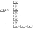
- a flow chart can be set up for treating an edentulous patient with a dental plate.
- the patient is defined with respect to certain parameters, for example jaw-bone status, age, etc. This definition takes place in the block 143. Thereafter, the patient's status is defined in relation to earlier experience in the block 144. This comparison function can be performed by the surgeon or prosthetist. Advantages of the desired dental situation are defined in the block 145. This definition takes place on consultation between patient and surgeon.
- a model production for example production of a drill model, is defined in block 146.
- the X-ray situation is defined in the block 147, for example whether X-ray tomography will be used, whether this will be done at hospital or by computer tomography.
- the production function using preferably three-dimensional CADD equipment is defined in block 148. If stereolithography equipment is to be used for producing the model, this is done in block 149.
- a plastic model with fixture markings is defined in a block 150.
- the dental technician's work is defined in block 151.
- Preparations for surgery are defined in block 152.
- the other parameters used for data programming are implemented, see above.
Landscapes
- Health & Medical Sciences (AREA)
- Business, Economics & Management (AREA)
- Engineering & Computer Science (AREA)
- Human Resources & Organizations (AREA)
- Oral & Maxillofacial Surgery (AREA)
- Strategic Management (AREA)
- General Health & Medical Sciences (AREA)
- Public Health (AREA)
- Veterinary Medicine (AREA)
- Entrepreneurship & Innovation (AREA)
- Animal Behavior & Ethology (AREA)
- Life Sciences & Earth Sciences (AREA)
- Epidemiology (AREA)
- Dentistry (AREA)
- Data Mining & Analysis (AREA)
- General Physics & Mathematics (AREA)
- Manufacturing & Machinery (AREA)
- Chemical & Material Sciences (AREA)
- Economics (AREA)
- Marketing (AREA)
- Operations Research (AREA)
- Quality & Reliability (AREA)
- Tourism & Hospitality (AREA)
- Physics & Mathematics (AREA)
- General Business, Economics & Management (AREA)
- Materials Engineering (AREA)
- Theoretical Computer Science (AREA)
- Dental Tools And Instruments Or Auxiliary Dental Instruments (AREA)
- Dental Prosthetics (AREA)
- Transition And Organic Metals Composition Catalysts For Addition Polymerization (AREA)
- Materials For Medical Uses (AREA)
- Steroid Compounds (AREA)
- Electrotherapy Devices (AREA)
- Prostheses (AREA)
- Dental Preparations (AREA)
Claims (5)
- Verfahren zur Herstellung einer Montageschablone und eines Zahnersatzes, gekennzeichnet durcha) Eingabe einer ersten Darstellung (98) von Röntgentomographiedaten eines Kieferknochens (96) eines Patienten in eine Computerausrüstung (106), die bei einer ersten Partei angeordnet ist,b) Eingabe einer zweiten Darstellung (103) von Scan- oder Lesedaten einer losen Prothese oder eines Modells davon (100) in die Computerausrüstung (106), die bei der ersten Partei angeordnet ist,c) Simulieren virtueller Bilder (108, 109) der ersten Darstellung und der zweiten Darstellung auf einem Computerbildschirm (110);d) Koordinieren, in der Computerausrüstung (106), der simulierten virtuellen Bilder und Planen optimaler Applikationen virtueller Haltevorrichtungen (111, 112) in dem virtuellen Bild (108) der ersten Darstellung durch die erste Partei,e) Übertragen von Computerinformationen, welche die koordinierte Konfiguration der virtuellen Bilder (108, 109) der ersten und zweiten Darstellungen und die virtuellen Haltevorrichtungen (111, 112) betreffen, zu einer zweiten Partei,f) Herstellung als Funktion der übertragenen und dadurch empfangenen Computerinformationen eines tatsächlichen Models (123) der ersten und zweiten Darstellungen (98, 106) durch die zweite Partei, wobei sich in dem tatsächlichen Modell Elemente erstrecken und in Positionen und Richtungen angeordnet sind, die den Positionen und Richtungen der virtuellen Haltevorrichtungen (111, 112) entsprechen, und wobei das tatsächliche Modell (123) ein Modell des Kieferknochens und ein Modell der losen Prothese oder des Modells davon umfasst,g) Übertragung des tatsächlichen Modells (123) zu der dritten Partei,h) Übertragung eines Kiefermodells des gegenüberliegenden Kiefers (116) und eines Bissregisterindex zu der dritten Partei,i) Verwendung, durch die dritte Partei, eines Artikulators, um, mittels des tatsächlichen Modells (123), des Kiefermodells des gegenüberliegenden Kiefers (116) und des Bissregisterindex, den Biss des Patienten zu bestimmen, unter Berücksichtigung des Weichegeweberaums zwischen Kieferknochen und Zahn,j) Herstellung, durch die dritte Partei, mit Hilfe des Modells des Kieferknochens, einer Montageschablone mit definierter Applikationsposition gegen das Modell des Kieferknochens und gegen Haltevorrichtungsplatzhalter, die in den Elementen angeordnet sind, und dadurch vorsehen identifizierter Richtungen und Positionen für Haltevorrichtungen und somit für geplante Ausnehmungen in dem Kieferknochen des Patienten undk) Herstellung, durch die dritte Partei, einer Zahnbrücke (85) mittels des Modells des Kieferknochens und der Haltevorrichtungsplatzhalter (87).
- Verfahren gemäß Anspruch 1, gekennzeichnet durch Konstruieren des tatsächlichen Modells (123) in zwei Teilen, wobei der erste Teil den Kieferknochen des Patienten darstellt und der zweite Teil die lose Prothese oder das Modell davon darstellt und die ersten und zweiten Teile voneinander durch einen Zwischenraum getrennt sind, um die Anwendung in dem Artikulator zu erlauben.
- Verfahren gemäß Anspruch 1, das die Herstellung des tatsächlichen Modells (123) mit der Hilfe von Stereolithographie umfasst.
- Verfahren gemäß Anspruch 1, welches das Herstellen des tatsächlichen Modells (123) mit einem Element umfasst, das ein röhrenförmiges Element ist, das sich in das tatsächliche Modell (123) erstreckt.
- Verfahren gemäß Anspruch 1, unter Anbringung von Abstandshaltern (92) an den Haltevorrichtungsplatzhaltern (87), Sichern von Zementierhülsen (93) auf den Abstandshaltern (92) und Herstellen der Zahnbrücke (85) mit der Hilfe des Modells des Kieferknochens, der Abstandshalter und der Hülsen (93).
Priority Applications (1)
| Application Number | Priority Date | Filing Date | Title |
|---|---|---|---|
| EP10010972.7A EP2319451B1 (de) | 2000-12-29 | 2001-12-27 | Verfahren für einen Protheseneinsatz |
Applications Claiming Priority (3)
| Application Number | Priority Date | Filing Date | Title |
|---|---|---|---|
| SE0004884 | 2000-12-29 | ||
| SE0004884A SE522958C2 (sv) | 2000-12-29 | 2000-12-29 | Förfarande, arrangemang (anordning) och program vid eller för protetisk installation |
| PCT/SE2001/002898 WO2002053056A1 (en) | 2000-12-29 | 2001-12-27 | Method, arrangement and program for a prosthetic installation |
Related Child Applications (2)
| Application Number | Title | Priority Date | Filing Date |
|---|---|---|---|
| EP10010972.7A Division EP2319451B1 (de) | 2000-12-29 | 2001-12-27 | Verfahren für einen Protheseneinsatz |
| EP10010972.7 Division-Into | 2010-09-28 |
Publications (2)
| Publication Number | Publication Date |
|---|---|
| EP1347713A1 EP1347713A1 (de) | 2003-10-01 |
| EP1347713B1 true EP1347713B1 (de) | 2011-03-02 |
Family
ID=20282459
Family Applications (2)
| Application Number | Title | Priority Date | Filing Date |
|---|---|---|---|
| EP01272996A Expired - Lifetime EP1347713B1 (de) | 2000-12-29 | 2001-12-27 | Verfahren für eine protheseninstallation |
| EP10010972.7A Expired - Lifetime EP2319451B1 (de) | 2000-12-29 | 2001-12-27 | Verfahren für einen Protheseneinsatz |
Family Applications After (1)
| Application Number | Title | Priority Date | Filing Date |
|---|---|---|---|
| EP10010972.7A Expired - Lifetime EP2319451B1 (de) | 2000-12-29 | 2001-12-27 | Verfahren für einen Protheseneinsatz |
Country Status (11)
| Country | Link |
|---|---|
| US (2) | US7175435B2 (de) |
| EP (2) | EP1347713B1 (de) |
| JP (1) | JP2004522489A (de) |
| AT (1) | ATE499900T1 (de) |
| AU (1) | AU2002217690B2 (de) |
| BR (1) | BR0116644B1 (de) |
| CA (1) | CA2432953C (de) |
| DE (1) | DE60144159D1 (de) |
| ES (2) | ES2362348T3 (de) |
| SE (1) | SE522958C2 (de) |
| WO (1) | WO2002053056A1 (de) |
Families Citing this family (78)
| Publication number | Priority date | Publication date | Assignee | Title |
|---|---|---|---|---|
| ATE555743T1 (de) | 2000-11-08 | 2012-05-15 | Straumann Inst Ag | (dentale) oberflächenerfassung und erzeugung |
| SE522958C2 (sv) | 2000-12-29 | 2004-03-16 | Nobel Biocare Ab | Förfarande, arrangemang (anordning) och program vid eller för protetisk installation |
| SE520765C2 (sv) | 2001-12-28 | 2003-08-19 | Nobel Biocare Ab | Anordning och arrangemang för att medelst mall ta upp hål till implantat i ben, företrädesvis käkben |
| US7574025B2 (en) | 2002-01-16 | 2009-08-11 | I-Dent Imaging, Inc. | Oral implant template |
| JP4069701B2 (ja) * | 2002-07-31 | 2008-04-02 | 株式会社日立製作所 | 作業支援装置 |
| SE526671C2 (sv) * | 2002-11-27 | 2005-10-25 | Nobel Biocare Ab | Anordning för att förfärdiga hela eller delar av tandersättning |
| SE526666C2 (sv) * | 2002-12-30 | 2005-10-25 | Nobel Biocare Ab | Anordning och arrangemang för fixturinstallation |
| SE526665C2 (sv) * | 2002-12-30 | 2005-10-25 | Nobel Biocare Ab | Anordning vid dentalt fastskruvningsarrangemang |
| SE526679C2 (sv) * | 2003-11-12 | 2005-10-25 | Nobel Biocare Ab | System och anordning för framtagning av dental ersättningsutrustning samt sådan utrustning |
| SE526223C2 (sv) * | 2003-12-10 | 2005-08-02 | Nobel Biocare Ab | System och anordning vid framställning och isättning av tandbrouppbyggnad |
| SE527503C2 (sv) * | 2004-08-05 | 2006-03-21 | Nobel Biocare Ab | Anordning och förfarande för att underlätta applicering till rätt läge av tand- eller tandrestmall |
| US20060115790A1 (en) * | 2004-11-26 | 2006-06-01 | Michael Alon | Method and accessory for preparing a dental crown or bridge |
| US8055487B2 (en) * | 2005-02-22 | 2011-11-08 | Smith & Nephew, Inc. | Interactive orthopaedic biomechanics system |
| EP1906862B1 (de) * | 2005-06-30 | 2018-05-23 | Biomet 3i, LLC | Verfahren zur erstellung eines models für einen dentallabor |
| DE102005035475B4 (de) * | 2005-07-28 | 2019-08-08 | Institut Straumann Ag | Verfahren, computerlesbares Medium, Computerprogramm die Herstellung von Zahnersatzteilen betreffend |
| ITBO20050545A1 (it) | 2005-09-06 | 2007-03-07 | Federico Franchini | Serie di strumenti chirurgici per implantologia dentale |
| US20070059665A1 (en) * | 2005-09-09 | 2007-03-15 | Facial Imaging, Llc | Image data processing for dental implant professionals |
| US11219511B2 (en) | 2005-10-24 | 2022-01-11 | Biomet 3I, Llc | Methods for placing an implant analog in a physical model of the patient's mouth |
| US8257083B2 (en) | 2005-10-24 | 2012-09-04 | Biomet 3I, Llc | Methods for placing an implant analog in a physical model of the patient's mouth |
| JP4738152B2 (ja) * | 2005-12-02 | 2011-08-03 | 富士通株式会社 | 歯科治療を支援するシミュレーションプログラム |
| US7840042B2 (en) | 2006-01-20 | 2010-11-23 | 3M Innovative Properties Company | Superposition for visualization of three-dimensional data acquisition |
| US7698014B2 (en) * | 2006-01-20 | 2010-04-13 | 3M Innovative Properties Company | Local enforcement of accuracy in fabricated models |
| US8540510B2 (en) | 2006-05-04 | 2013-09-24 | Nobel Biocare Services Ag | Device for securing a dental implant in bone tissue, a method for making a surgical template and a method of securing a dental implant in bone tissue |
| US7653455B2 (en) * | 2006-07-28 | 2010-01-26 | 3M Innovative Properties Company | Computer-aided implanting of orthodontic anchorage devices using surgical guides |
| WO2008051131A1 (en) * | 2006-10-27 | 2008-05-02 | Nobel Biocare Services Ag | Dental model, articulator and methods for production |
| DK3085330T3 (en) | 2006-10-27 | 2018-09-03 | Nobel Biocare Services Ag | METHOD AND APPARATUS FOR OBTAINING DATA FOR A DENTAL COMPONENT AND A PHYSICAL DENTAL MODEL |
| WO2008051129A1 (en) | 2006-10-27 | 2008-05-02 | Nobel Biocare Services Ag | A dental impression tray for use in obtaining an impression of a dental structure |
| DE102006061134A1 (de) * | 2006-12-22 | 2008-06-26 | Aepsilon Rechteverwaltungs Gmbh | Verfahren betreffend den Transport von Zahnersatzteilen |
| DE102006061143A1 (de) * | 2006-12-22 | 2008-07-24 | Aepsilon Rechteverwaltungs Gmbh | Verfahren, computerlesbares Medium und Computer betreffend die Herstellung von Zahnersatzteilen |
| US9508106B1 (en) * | 2006-12-29 | 2016-11-29 | David A. Salamassy | Method and system for provisioning of dental implants and related services |
| CN101578076B (zh) | 2007-01-10 | 2013-10-23 | 诺贝尔生物服务公司 | 用于牙设计和制备的方法和系统 |
| US20100137881A1 (en) * | 2007-02-22 | 2010-06-03 | Lukas Kamer | Arrangement for Planning and Carrying Out a Surgical Procedure |
| US8206153B2 (en) | 2007-05-18 | 2012-06-26 | Biomet 3I, Inc. | Method for selecting implant components |
| AU2008256518B2 (en) | 2007-05-25 | 2014-02-06 | Nobel Biocare Services Ag | Method and system for dental planning |
| DE102007027408B3 (de) * | 2007-06-12 | 2009-01-02 | Luthardt, Ralph Gunnar, Prof. Dr. | Verfahren zur flexiblen netzwerkbasierten Datenverarbeitung zur Herstellung von patientenspezifischen Medizinprodukten |
| US8265949B2 (en) | 2007-09-27 | 2012-09-11 | Depuy Products, Inc. | Customized patient surgical plan |
| US9173662B2 (en) | 2007-09-30 | 2015-11-03 | DePuy Synthes Products, Inc. | Customized patient-specific tibial cutting blocks |
| US9786022B2 (en) | 2007-09-30 | 2017-10-10 | DePuy Synthes Products, Inc. | Customized patient-specific bone cutting blocks |
| US8357111B2 (en) | 2007-09-30 | 2013-01-22 | Depuy Products, Inc. | Method and system for designing patient-specific orthopaedic surgical instruments |
| WO2011106399A1 (en) | 2010-02-25 | 2011-09-01 | Depuy Products, Inc. | Customized patient-specific bone cutting blocks |
| US8398645B2 (en) | 2007-09-30 | 2013-03-19 | DePuy Synthes Products, LLC | Femoral tibial customized patient-specific orthopaedic surgical instrumentation |
| DE102007052389A1 (de) * | 2007-10-31 | 2009-05-07 | Sicat Gmbh & Co. Kg | Verfahren zur Herstellung einer Behandlungsschablone |
| EP2060240A3 (de) | 2007-11-16 | 2009-08-12 | Biomet 3i, LLC | Komponenten zur Verwendung mit einer chirurgischen Schablone für eine Zahnimplantatplatzierung |
| ES2683119T3 (es) | 2008-04-15 | 2018-09-25 | Biomet 3I, Llc | Método de creación de un modelo dental digital preciso de huesos y tejidos blandos |
| EP3000430B1 (de) | 2008-04-16 | 2017-11-15 | Biomet 3i, LLC | Verfahren zur virtuellen entwicklung einer chirurgischen führung für zahnärztliche implantate |
| US20100035212A1 (en) * | 2008-08-11 | 2010-02-11 | Jean Robichaud | Preparation of dental implant surgery and prosthesis installation |
| EP2254068B1 (de) | 2009-05-18 | 2020-08-19 | Nobel Biocare Services AG | Verfahren und System, die einen verbesserten Datenabgleich zur virtuellen Planung bereitstellen |
| EP2292175B1 (de) | 2009-09-07 | 2016-08-17 | Nobel Biocare Services AG | Komponenten zum geführten Gewindeschneiden von Knochen |
| EP2292176B1 (de) | 2009-09-07 | 2019-01-09 | Nobel Biocare Services AG | Implantations-Set |
| EP2538855A4 (de) | 2010-02-25 | 2016-08-03 | Depuy Products Inc | Angepasste patientenspezifische schienbeinschneideblöcke |
| US10149722B2 (en) * | 2010-02-25 | 2018-12-11 | DePuy Synthes Products, Inc. | Method of fabricating customized patient-specific bone cutting blocks |
| ES2477288T3 (es) | 2010-12-07 | 2014-07-16 | Biomet 3I, Llc | Elemento de exploración universal para su uso en un implante dental y en análogos de implante dental |
| DE102011003557B9 (de) * | 2011-02-03 | 2012-09-06 | Sirona Dental Systems Gmbh | Bohrschablone für ein dentales Implantat, ein Verfahren zur Herstellung dieser Bohrschablone sowie eine Vorrichtung zur Überprüfung der Bohrschablone und deren Verwendung |
| US8636618B2 (en) * | 2011-02-17 | 2014-01-28 | GM Global Technology Operations LLC | Clutch and gear arrangement for a front wheel drive vehicle |
| AU2012255865B8 (en) | 2011-05-16 | 2015-06-04 | Biomet 3I, Llc | Temporary abutment with combination of scanning features and provisionalization features |
| US8641721B2 (en) | 2011-06-30 | 2014-02-04 | DePuy Synthes Products, LLC | Customized patient-specific orthopaedic pin guides |
| US9452032B2 (en) | 2012-01-23 | 2016-09-27 | Biomet 3I, Llc | Soft tissue preservation temporary (shell) immediate-implant abutment with biological active surface |
| US9089382B2 (en) | 2012-01-23 | 2015-07-28 | Biomet 3I, Llc | Method and apparatus for recording spatial gingival soft tissue relationship to implant placement within alveolar bone for immediate-implant placement |
| GB201216224D0 (en) | 2012-09-12 | 2012-10-24 | Nobel Biocare Services Ag | An improved virtual splint |
| GB201216230D0 (en) | 2012-09-12 | 2012-10-24 | Nobel Biocare Services Ag | An improved surgical template |
| GB201216214D0 (en) | 2012-09-12 | 2012-10-24 | Nobel Biocare Services Ag | A digital splint |
| US20140080092A1 (en) | 2012-09-14 | 2014-03-20 | Biomet 3I, Llc | Temporary dental prosthesis for use in developing final dental prosthesis |
| EP2906141B1 (de) | 2012-10-10 | 2019-12-11 | James Harrison | Sockel zur positionierung einer endgültigen zahnprothese, system mit diesem sockel |
| US9408678B2 (en) | 2012-10-10 | 2016-08-09 | James Harrison | Cradle for positioning a final dental prosthesis and a system incorporating the cradle |
| US9173723B2 (en) | 2012-10-10 | 2015-11-03 | James Harrison | Method of installing a final dental prosthesis |
| US10383709B2 (en) | 2012-10-12 | 2019-08-20 | Nobel Biocare Services Ag | Dental bar |
| US8905757B2 (en) | 2012-12-03 | 2014-12-09 | E. Kats Enterprises Ltd. | Method and apparatus for measuring a location and orientation of a plurality of implants |
| US8926328B2 (en) | 2012-12-27 | 2015-01-06 | Biomet 3I, Llc | Jigs for placing dental implant analogs in models and methods of doing the same |
| EP3094283A4 (de) | 2013-12-20 | 2018-01-24 | Biomet 3i, LLC | Zahnärztliches system zur entwicklung von angepassten prothesen durch abtasten von codierten elementen |
| WO2015154125A1 (en) * | 2014-04-07 | 2015-10-15 | Instaguide Pty Ltd | Dental implant guide formation system |
| US9750582B1 (en) | 2014-06-09 | 2017-09-05 | L. Stephen Buchanan | Endodontic therapy system, apparatus and method making use of a disposable CT registration tray device with pre-set radiographic registration markers |
| US9700390B2 (en) | 2014-08-22 | 2017-07-11 | Biomet 3I, Llc | Soft-tissue preservation arrangement and method |
| US9795495B1 (en) * | 2014-08-23 | 2017-10-24 | Timothy Ray Miller | Instrumentation and methods for knee arthroplasty |
| EP3267936A4 (de) | 2015-03-09 | 2018-12-26 | Stephen J. Chu | Eiförmiges zahnfleisch-pontic und verfahren zur verwendung davon |
| ES2604122B2 (es) * | 2015-09-03 | 2017-11-30 | Leandro ARRANZ CALVO | Procedimiento para la obtención e implantación de coronas y puentes definitivos sobre implantes inmediatamente después de la cirugía |
| US20200311702A1 (en) * | 2017-12-05 | 2020-10-01 | Dsi Corporation | Dental technical fee automatic calculation system, dental technical fee automatic calculation method, and program |
| US11051829B2 (en) | 2018-06-26 | 2021-07-06 | DePuy Synthes Products, Inc. | Customized patient-specific orthopaedic surgical instrument |
| CN115068137A (zh) * | 2022-06-16 | 2022-09-20 | 江苏柯润玺医疗科技发展有限公司 | 个性化种植桥架制作方法 |
Family Cites Families (101)
| Publication number | Priority date | Publication date | Assignee | Title |
|---|---|---|---|---|
| GB1131948A (en) | 1966-07-01 | 1968-10-30 | Joe John Simmons | Dental appliance |
| US5788494A (en) | 1995-09-19 | 1998-08-04 | Shopvest, Inc. | Working model for prosthodontic preparation of a crown for installation on an implant fixture |
| US4315740A (en) | 1977-04-18 | 1982-02-16 | Mercer Roger W | Apparatus for mounting dental casts |
| US4470815A (en) | 1983-03-17 | 1984-09-11 | Hazco Development, Inc. | Method of making custom dentures |
| SE457691B (sv) | 1987-05-22 | 1989-01-23 | Nobel Plast Ab | Metod foer framstaellning av protetiska konstruktioner av kompositmaterial med betydande fiberinnehaall |
| US4850870C1 (en) | 1987-10-23 | 2001-07-24 | Implant Innovations Inc | Prosthodontic restoration components |
| US4832601A (en) | 1987-12-04 | 1989-05-23 | Hall Surgical | Adjustable support for a prosthetic tooth and method |
| DE3802789A1 (de) | 1988-01-29 | 1989-08-10 | Lauks Nikola | Bohrvorrichtung fuer kieferchirurgische implantatkavitaeten und verfahren zur herstellung einer bohrbuchsenschablone fuer implantatkavitaeten |
| US5015183A (en) | 1989-08-07 | 1991-05-14 | Fenick Thomas J | Locating device and method of placing a tooth implant |
| US5030096A (en) | 1989-10-02 | 1991-07-09 | Steri-Oss, Inc. | Implant healing cap and holder |
| US5062800A (en) | 1990-03-21 | 1991-11-05 | Core-Vent Corporation | Dental implant handle, and dental implant package including a dental implant handle |
| US5743916A (en) | 1990-07-13 | 1998-04-28 | Human Factors Industrial Design, Inc. | Drill guide with removable ferrules |
| US5106300A (en) | 1990-09-26 | 1992-04-21 | Voitik Anton J | Dental implant attachment structure and method |
| US5766221A (en) | 1991-12-03 | 1998-06-16 | Boston Scientific Technology, Inc. | Bone anchor implantation device |
| US5350297A (en) | 1991-12-24 | 1994-09-27 | Cohen Robert N | Method and apparatus for recording the position of dental implants |
| GB9208442D0 (en) | 1992-04-16 | 1992-06-03 | Asher George B | Tooth & selection joint & jig(dental implants) |
| US5213502A (en) | 1992-06-10 | 1993-05-25 | Fereidoun Daftary | Interlockable two-piece impression coping for anatomical dental abutment restorative systems |
| US5320529A (en) * | 1992-09-09 | 1994-06-14 | Howard C. Weitzman | Method and apparatus for locating an ideal site for a dental implant and for the precise surgical placement of that implant |
| IT1260239B (it) | 1992-12-22 | 1996-04-02 | Metodo per la realizzazione di protesi da implantologia e dispositivo per l'attuazione di tale metodo | |
| NL9301308A (nl) | 1993-07-26 | 1995-02-16 | Willem Frederick Van Nifterick | Werkwijze voor het vastzetten van een tandprothese op implantaten in het kaakbeen van een patiënt en middel te gebruiken daarbij. |
| CA2107262C (en) | 1993-09-29 | 2006-12-19 | Milan Somborac | Dental implant |
| US5662473A (en) | 1993-12-02 | 1997-09-02 | Vident | Adjustable-angulation pattern for making a dental-implant abutment |
| SE502035C2 (sv) | 1993-12-06 | 1995-07-24 | Nobelpharma Ab | Metod och och anordning för framtagning av information för framställning av artifiella stödorgan eller ersättningsdelar till människokroppen |
| US5492471A (en) | 1994-03-23 | 1996-02-20 | Gary Singer | Healing cap system |
| US5482463A (en) | 1994-04-08 | 1996-01-09 | Wilson, Jr.; Richard S. | Anti-slippage mechanism for dental implant components |
| BE1008372A3 (nl) | 1994-04-19 | 1996-04-02 | Materialise Nv | Werkwijze voor het vervaardigen van een geperfektioneerd medisch model uitgaande van digitale beeldinformatie van een lichaamsdeel. |
| SE507134C2 (sv) | 1994-05-31 | 1998-04-06 | Nobelpharma Ab | Indikeringsanordning och förfarande för utmärkning och upptagning av en eller flera fästpunkter till fixtur(-er) i människokroppsdel, företrädesvis käke |
| US5577912A (en) | 1994-09-19 | 1996-11-26 | Prins; Steven P. | Adjustable implant fixture |
| DE9420038U1 (de) | 1994-12-14 | 1995-02-09 | Hartmann, Alexander, 79104 Freiburg | Implantateinrichtung |
| US5613852A (en) | 1995-01-06 | 1997-03-25 | Board Of Regents Univ Of Ne At Lincoln | Dental implant drill guide system |
| US5605457A (en) | 1995-02-13 | 1997-02-25 | Crystal Medical Technology, A Division Of Folsom Metal Products, Inc. | Implant connector |
| US5605458A (en) | 1995-03-06 | 1997-02-25 | Crystal Medical Technology, A Division Of Folsom Metal Products, Inc. | Negative load flank implant connector |
| US5607304A (en) | 1995-04-17 | 1997-03-04 | Crystal Medical Technology, A Division Of Folsom Metal Products, Inc. | Implant connector |
| DE19518702C2 (de) | 1995-05-22 | 1999-03-11 | Sirona Dental Systems Gmbh | Verfahren und Einrichtung zur rechnergestützten Restauration von Zähnen |
| DE19534979C1 (de) | 1995-09-20 | 1997-01-09 | Imz Fertigung Vertrieb | Enossales Einzelzahnimplantat mit Verdrehsicherung |
| US5718579A (en) | 1995-12-05 | 1998-02-17 | Kennedy; Brent D. | Drill guide kit |
| US5681167A (en) | 1996-01-05 | 1997-10-28 | Lazarof; Sargon | Dental assembly and process for preparing a tooth prosthesis |
| US5725376A (en) | 1996-02-27 | 1998-03-10 | Poirier; Michel | Methods for manufacturing a dental implant drill guide and a dental implant superstructure |
| US7331786B2 (en) | 1996-02-27 | 2008-02-19 | Technique D'usinage Sinlab Inc. | Manufacturing a dental implant drill guide and a dental implant superstructure |
| US6814575B2 (en) | 1997-02-26 | 2004-11-09 | Technique D'usinage Sinlab Inc. | Manufacturing a dental implant drill guide and a dental implant superstructure |
| US6382975B1 (en) * | 1997-02-26 | 2002-05-07 | Technique D'usinage Sinlab Inc. | Manufacturing a dental implant drill guide and a dental implant superstructure |
| EP0807422B1 (de) | 1996-05-17 | 2004-11-03 | Brandestini, Marco, Dr. | Verfahren zur Herstellung dentaler Rekonstruktionen und Rohling zur Durchführung des Verfahrens |
| SE506850C2 (sv) | 1996-06-27 | 1998-02-16 | Medevelop Ab | Tandprotessystem, komponenter för tandprotessystem jämte förfaranden vid dylika tandprotessystem |
| SE506947C2 (sv) | 1996-07-04 | 1998-03-09 | Nobel Biocare Ab | Anordning vid implantatsystem |
| SE508662C2 (sv) | 1996-08-27 | 1998-10-26 | Nobel Biocare Ab | Metod och monteringssats för förankringselement för tandben |
| GB2318058B (en) | 1996-09-25 | 2001-03-21 | Ninian Spenceley Peckitt | Improvements relating to prosthetic implants |
| US5769850A (en) | 1996-10-16 | 1998-06-23 | Chin; Martin | Apparatus and method for submergible, self-retaining distraction osteogenesis |
| SE512050C2 (sv) | 1997-01-21 | 2000-01-17 | Nobel Biocare Ab | Rotationssymmetriskt benförankringselement |
| US6619958B2 (en) | 1997-04-09 | 2003-09-16 | Implant Innovations, Inc. | Implant delivery system |
| SE509141C2 (sv) | 1997-04-10 | 1998-12-07 | Nobel Biocare Ab | Arrangemang och system för dental produktframställning och informationsgivning |
| US5989028A (en) | 1997-05-15 | 1999-11-23 | Core-Vent Corporation | Non-submergible, one-part, root-form endosseous dental implants |
| US6705863B2 (en) | 1997-06-20 | 2004-03-16 | Align Technology, Inc. | Attachment devices and methods for a dental appliance |
| JP2001510705A (ja) | 1997-07-25 | 2001-08-07 | ノベル バイオケアー アーベー (パブル) | オッセオインテグレーテッド・インプラントの印象用コーピングシステム |
| US5967305A (en) | 1997-09-17 | 1999-10-19 | Blonder; Howard | Dental implant component package and holder |
| SE510956C2 (sv) | 1997-11-11 | 1999-07-12 | Nobel Biocare Ab | Anordning för förankring av ett gängat implantat i ben, t ex tandben, medelst ett fastvridningsverktyg |
| US5967777A (en) | 1997-11-24 | 1999-10-19 | Klein; Michael | Surgical template assembly and method for drilling and installing dental implants |
| US5876204A (en) | 1997-11-25 | 1999-03-02 | Sulzer Calcitek Inc. | Dental implant positioning guide |
| EP1043960B1 (de) | 1997-12-18 | 2003-09-03 | Technique d'Usage Sinlab Inc. | Verfahren zur herstellung einer zahnimplantatsuprastruktur |
| SE512083C2 (sv) | 1998-05-29 | 2000-01-24 | Nobel Biocare Ab | Metod att producera dental första påbyggnadsdel till implantat eller annan påbyggnadsdel samt hållare för modell av den första påbyggnadsdelen |
| DE19828479A1 (de) | 1998-06-26 | 1999-12-30 | Friatec Ag | Übertragungselement |
| US6159008A (en) | 1998-07-13 | 2000-12-12 | Steri-Oss Inc. | Implant carrier with gripping fingers |
| US6217332B1 (en) | 1998-07-13 | 2001-04-17 | Nobel Biocare Ab | Combination implant carrier and vial cap |
| AU5558099A (en) | 1998-08-12 | 2000-03-06 | Nobel Biocare Ab | One-step threaded implant |
| SE513111C2 (sv) | 1998-11-11 | 2000-07-10 | Nobel Biocare Ab | Gängförsett implantat och anordning och metod vid ett sådant implantat |
| US6287115B1 (en) | 1998-11-17 | 2001-09-11 | L. Paul Lustig | Dental implant and tool and method for effecting a dental restoration using the same |
| SE513778C2 (sv) | 1999-03-18 | 2000-11-06 | Nobel Biocare Ab | Förfarande, arrangemang och användning för applicering av distans till implantat medelst skruv. |
| US6287117B1 (en) | 1999-04-22 | 2001-09-11 | Sulzer Dental Inc. | Endosseous dental implants including a healing screw and an optional implant extender |
| DE19932877B4 (de) | 1999-07-16 | 2006-10-26 | Hint-Els Gmbh | Dentalprothesen-Rohling |
| US6099311A (en) | 1999-07-28 | 2000-08-08 | Sulzer Calcitek Inc. | Abutment delivery system |
| FR2797171B1 (fr) | 1999-08-06 | 2002-02-08 | Bruno Jacques Hubert Bompard | Dispositif pour la mise en place d'implant dentaire |
| US6561805B2 (en) | 1999-08-12 | 2003-05-13 | Nobel Biocare Ab | Universal implant delivery system |
| US7234937B2 (en) | 1999-11-30 | 2007-06-26 | Orametrix, Inc. | Unified workstation for virtual craniofacial diagnosis, treatment planning and therapeutics |
| DE10009448C2 (de) | 2000-02-29 | 2002-04-11 | Robert Laux | Zahn- oder Kiefersegment auf einem Basisträger |
| SE515632C2 (sv) | 2000-01-31 | 2001-09-17 | Nobel Biocare Ab | Förfarande och anordning vid superstruktur till implantat |
| DE20002376U1 (de) | 2000-02-11 | 2000-05-18 | Hein, Wolfram, 56593 Horhausen | Zahnzwischenraumreiniger mit gelenkiger Reinigungsspitze und Handgriff |
| US6227861B1 (en) | 2000-02-29 | 2001-05-08 | Richard G. Cartledge | Preformed mandibular splint |
| AR014089A1 (es) * | 2000-06-16 | 2001-02-07 | Ranalli Sebastian Luciano | Dispositivo para la planificacion y posterior colocacion de un implante dentario, metodo para planificar la correcta colocacion de un implante dentario queemplea dicho dispositivo y guia pretomografica y plantilla quirurgica obtenidas mediante dicho metodo |
| US6482284B1 (en) | 2000-08-31 | 2002-11-19 | 3M Innovative Properties Company | Method of making a dental mill blank and support stub assembly |
| EP1205159A1 (de) | 2000-11-13 | 2002-05-15 | Yves Germanier | Positioniervorrichtung zum Einsetzen von Implantat getragenen Zahnprothesen |
| US20020064759A1 (en) * | 2000-11-30 | 2002-05-30 | Durbin Duane Milford | Method and system for viewing, altering and archiving digital models of dental structures and computer integrated manufacturing of physical models of dental structures |
| SE522958C2 (sv) | 2000-12-29 | 2004-03-16 | Nobel Biocare Ab | Förfarande, arrangemang (anordning) och program vid eller för protetisk installation |
| SE517011C2 (sv) | 2000-12-29 | 2002-04-02 | Nobel Biocare Ab | Anordning för hålupptagning och hylsisättning i enhet som ingår i dental uppbyggnadsdel |
| SE522965C2 (sv) | 2000-12-29 | 2004-03-16 | Nobel Biocare Ab | Anordning för att åstadkomma lägesbestämning |
| US6793491B2 (en) | 2001-03-08 | 2004-09-21 | Implant Logic Systems | Stabilizing implant system |
| US6672870B2 (en) | 2001-03-20 | 2004-01-06 | John G. Knapp | Method and instrumentation for attaching dentures |
| JP3522233B2 (ja) | 2001-04-17 | 2004-04-26 | Necパーソナルプロダクツ株式会社 | 記録装置のロード機構 |
| EP1317910A1 (de) | 2001-12-06 | 2003-06-11 | KerrHawe SA | Medizinisches Instrument zur Verwendung mit Flüssigkeiten |
| SE520765C2 (sv) | 2001-12-28 | 2003-08-19 | Nobel Biocare Ab | Anordning och arrangemang för att medelst mall ta upp hål till implantat i ben, företrädesvis käkben |
| US6692254B1 (en) | 2002-02-01 | 2004-02-17 | Barry A. Kligerman | Implant supported dental prosthesis foundation bar |
| FR2836372B1 (fr) | 2002-02-28 | 2004-06-04 | Obl | Procede et dispositif pour la mise en place d'implants dentaires |
| IL158789A (en) | 2002-11-13 | 2009-11-18 | Biomet 3I Llc | Dental implant system |
| SE526666C2 (sv) | 2002-12-30 | 2005-10-25 | Nobel Biocare Ab | Anordning och arrangemang för fixturinstallation |
| SE526665C2 (sv) | 2002-12-30 | 2005-10-25 | Nobel Biocare Ab | Anordning vid dentalt fastskruvningsarrangemang |
| US7021934B2 (en) | 2003-01-21 | 2006-04-04 | Zimmer Dental, Inc. | Multi-adjustable drill guide and framework system for dental prosthetics |
| US7014461B2 (en) | 2003-01-23 | 2006-03-21 | Tactile Technologies Llc | Hard tissue surface geometry determination |
| SE526223C2 (sv) | 2003-12-10 | 2005-08-02 | Nobel Biocare Ab | System och anordning vid framställning och isättning av tandbrouppbyggnad |
| SE527504C2 (sv) | 2004-08-05 | 2006-03-21 | Nobel Biocare Ab | Styranordning samverkbar med ett antal i tandmall anordnade hylsor |
| SE527503C2 (sv) | 2004-08-05 | 2006-03-21 | Nobel Biocare Ab | Anordning och förfarande för att underlätta applicering till rätt läge av tand- eller tandrestmall |
| BE1016374A3 (fr) | 2005-02-03 | 2006-09-05 | Moyer Philippe Albert Paul Ghi | Procede de fabrication d'une prothese dentaire et appareillage mis en oeuvre. |
| US8540510B2 (en) | 2006-05-04 | 2013-09-24 | Nobel Biocare Services Ag | Device for securing a dental implant in bone tissue, a method for making a surgical template and a method of securing a dental implant in bone tissue |
| US20080220390A1 (en) | 2007-03-07 | 2008-09-11 | Michael Klein | Dental tool guide assembly |
-
2000
- 2000-12-29 SE SE0004884A patent/SE522958C2/sv not_active IP Right Cessation
-
2001
- 2001-12-27 US US10/451,535 patent/US7175435B2/en not_active Ceased
- 2001-12-27 US US12/371,545 patent/USRE43584E1/en not_active Expired - Lifetime
- 2001-12-27 DE DE60144159T patent/DE60144159D1/de not_active Expired - Lifetime
- 2001-12-27 AT AT01272996T patent/ATE499900T1/de not_active IP Right Cessation
- 2001-12-27 WO PCT/SE2001/002898 patent/WO2002053056A1/en not_active Ceased
- 2001-12-27 ES ES01272996T patent/ES2362348T3/es not_active Expired - Lifetime
- 2001-12-27 EP EP01272996A patent/EP1347713B1/de not_active Expired - Lifetime
- 2001-12-27 ES ES10010972.7T patent/ES2574604T3/es not_active Expired - Lifetime
- 2001-12-27 BR BRPI0116644-1A patent/BR0116644B1/pt not_active IP Right Cessation
- 2001-12-27 AU AU2002217690A patent/AU2002217690B2/en not_active Ceased
- 2001-12-27 CA CA2432953A patent/CA2432953C/en not_active Expired - Fee Related
- 2001-12-27 EP EP10010972.7A patent/EP2319451B1/de not_active Expired - Lifetime
- 2001-12-27 JP JP2002554008A patent/JP2004522489A/ja active Pending
Also Published As
| Publication number | Publication date |
|---|---|
| ATE499900T1 (de) | 2011-03-15 |
| CA2432953A1 (en) | 2002-07-11 |
| AU2002217690B2 (en) | 2006-10-12 |
| SE522958C2 (sv) | 2004-03-16 |
| DE60144159D1 (de) | 2011-04-14 |
| ES2362348T3 (es) | 2011-07-01 |
| ES2574604T3 (es) | 2016-06-21 |
| EP2319451A2 (de) | 2011-05-11 |
| US20040078212A1 (en) | 2004-04-22 |
| EP2319451B1 (de) | 2016-03-16 |
| EP2319451A3 (de) | 2015-01-07 |
| USRE43584E1 (en) | 2012-08-14 |
| BR0116644B1 (pt) | 2012-08-21 |
| US7175435B2 (en) | 2007-02-13 |
| SE0004884D0 (sv) | 2000-12-29 |
| WO2002053056A1 (en) | 2002-07-11 |
| CA2432953C (en) | 2015-10-06 |
| EP1347713A1 (de) | 2003-10-01 |
| BR0116644A (pt) | 2004-02-17 |
| JP2004522489A (ja) | 2004-07-29 |
| SE0004884L (sv) | 2002-06-30 |
Similar Documents
| Publication | Publication Date | Title |
|---|---|---|
| EP1347713B1 (de) | Verfahren für eine protheseninstallation | |
| AU2002217690A1 (en) | Method, arrangement and program for a prosthetic installation | |
| Mangano et al. | Artificial intelligence and augmented reality for guided implant surgery planning: a proof of concept | |
| US8083522B2 (en) | Method for tooth implants | |
| US20200155270A1 (en) | System and Method for the Design, Creation and Installation of Prostheses | |
| US20100105011A1 (en) | System, Method And Apparatus For Tooth Implant Planning And Tooth Implant Kits | |
| AU2004296166B2 (en) | System and arrangement for production and insertion of a dental bridge structure | |
| Lal et al. | Use of stereolithographic templates for surgical and prosthodontic implant planning and placement. Part I. The concept | |
| US7835811B2 (en) | Surgical guides and methods for positioning artificial teeth and dental implants | |
| US12251275B1 (en) | Method and system for provisioning of dental implants and related services | |
| Roberts et al. | Maxillary full‐arch reconstruction using a sequenced digital workflow | |
| US20200397540A1 (en) | Denture system and method of manufacturing a denture | |
| Van Der Zel | Implant planning and placement using optical scanning and cone beam CT technology | |
| Klein et al. | Guided surgery for full-arch implant-supported restorations | |
| Tasopoulos et al. | Computer-guided implant dentistry | |
| Plus | Photogrammetry for Guided | |
| Kumar et al. | To Study the Influence of Digital Dentistry on the Accuracy of Implant Positioning and Prosthesis Creation | |
| Jain et al. | Revisiting Diagnostic Tooth Preparation: An Underrecognized Pillar of Precision in Fixed Prosthodontics–A Narrative Review | |
| Levrini1a et al. | AESTETHIC DENTISTRY | |
| Marković | PREREQUISITES FOR SUCCESSFUL IMPLANT TREATMENT IN THE ESTHETIC ZONE | |
| Pikos et al. | Guided Surgery: Treatment Planning and Technique | |
| Akagawa | Prosthetic rehabilitation: KF Thomas. Pp. 312. 1994. New Malden, Quintessence. Hardback,£ 85.00. ISBN 1 85097 032 7 | |
| Nemade et al. | The All-on-4 Concept: A Paradigm Shift in Full-Arch Rehabilitation |
Legal Events
| Date | Code | Title | Description |
|---|---|---|---|
| PUAI | Public reference made under article 153(3) epc to a published international application that has entered the european phase |
Free format text: ORIGINAL CODE: 0009012 |
|
| 17P | Request for examination filed |
Effective date: 20030729 |
|
| AK | Designated contracting states |
Kind code of ref document: A1 Designated state(s): AT BE CH CY DE DK ES FI FR GB GR IE IT LI LU MC NL PT SE TR |
|
| AX | Request for extension of the european patent |
Extension state: AL LT LV MK RO SI |
|
| 17Q | First examination report despatched |
Effective date: 20061110 |
|
| 18D | Application deemed to be withdrawn |
Effective date: 20070321 |
|
| 18RA | Request filed for re-establishment of rights before grant |
Effective date: 20071228 |
|
| 18RA | Request filed for re-establishment of rights before grant |
Effective date: 20071228 |
|
| 18RR | Decision to grant the request for re-establishment of rights before grant |
Free format text: ANGENOMMEN Effective date: 20080130 |
|
| R18Z | Request filed for re-establishment of rights before grant (corrected) |
Effective date: 20071228 |
|
| 18RR | Decision to grant the request for re-establishment of rights before grant |
Free format text: ANGENOMMEN Effective date: 20080222 |
|
| R18Z | Request filed for re-establishment of rights before grant (corrected) |
Effective date: 20071228 |
|
| D18D | Application deemed to be withdrawn (deleted) | ||
| GRAP | Despatch of communication of intention to grant a patent |
Free format text: ORIGINAL CODE: EPIDOSNIGR1 |
|
| RTI1 | Title (correction) |
Free format text: METHOD FOR A PROSTHETIC INSTALLATION |
|
| RAP1 | Party data changed (applicant data changed or rights of an application transferred) |
Owner name: NOBEL BIOCARE SERVICES AG |
|
| GRAS | Grant fee paid |
Free format text: ORIGINAL CODE: EPIDOSNIGR3 |
|
| GRAA | (expected) grant |
Free format text: ORIGINAL CODE: 0009210 |
|
| AK | Designated contracting states |
Kind code of ref document: B1 Designated state(s): AT BE CH CY DE DK ES FI FR GB GR IE IT LI LU MC NL PT SE TR |
|
| REG | Reference to a national code |
Ref country code: CH Ref legal event code: EP |
|
| REG | Reference to a national code |
Ref country code: IE Ref legal event code: FG4D |
|
| REF | Corresponds to: |
Ref document number: 60144159 Country of ref document: DE Date of ref document: 20110414 Kind code of ref document: P |
|
| REG | Reference to a national code |
Ref country code: DE Ref legal event code: R096 Ref document number: 60144159 Country of ref document: DE Effective date: 20110414 |
|
| REG | Reference to a national code |
Ref country code: CH Ref legal event code: NV Representative=s name: E. BLUM & CO. AG PATENT- UND MARKENANWAELTE VSP |
|
| REG | Reference to a national code |
Ref country code: ES Ref legal event code: FG2A Ref document number: 2362348 Country of ref document: ES Kind code of ref document: T3 Effective date: 20110701 |
|
| REG | Reference to a national code |
Ref country code: NL Ref legal event code: VDEP Effective date: 20110302 |
|
| PG25 | Lapsed in a contracting state [announced via postgrant information from national office to epo] |
Ref country code: GR Free format text: LAPSE BECAUSE OF FAILURE TO SUBMIT A TRANSLATION OF THE DESCRIPTION OR TO PAY THE FEE WITHIN THE PRESCRIBED TIME-LIMIT Effective date: 20110603 Ref country code: SE Free format text: LAPSE BECAUSE OF FAILURE TO SUBMIT A TRANSLATION OF THE DESCRIPTION OR TO PAY THE FEE WITHIN THE PRESCRIBED TIME-LIMIT Effective date: 20110302 |
|
| PG25 | Lapsed in a contracting state [announced via postgrant information from national office to epo] |
Ref country code: NL Free format text: LAPSE BECAUSE OF FAILURE TO SUBMIT A TRANSLATION OF THE DESCRIPTION OR TO PAY THE FEE WITHIN THE PRESCRIBED TIME-LIMIT Effective date: 20110302 Ref country code: CY Free format text: LAPSE BECAUSE OF FAILURE TO SUBMIT A TRANSLATION OF THE DESCRIPTION OR TO PAY THE FEE WITHIN THE PRESCRIBED TIME-LIMIT Effective date: 20110302 Ref country code: FI Free format text: LAPSE BECAUSE OF FAILURE TO SUBMIT A TRANSLATION OF THE DESCRIPTION OR TO PAY THE FEE WITHIN THE PRESCRIBED TIME-LIMIT Effective date: 20110302 Ref country code: AT Free format text: LAPSE BECAUSE OF FAILURE TO SUBMIT A TRANSLATION OF THE DESCRIPTION OR TO PAY THE FEE WITHIN THE PRESCRIBED TIME-LIMIT Effective date: 20110302 |
|
| PG25 | Lapsed in a contracting state [announced via postgrant information from national office to epo] |
Ref country code: BE Free format text: LAPSE BECAUSE OF FAILURE TO SUBMIT A TRANSLATION OF THE DESCRIPTION OR TO PAY THE FEE WITHIN THE PRESCRIBED TIME-LIMIT Effective date: 20110302 |
|
| PG25 | Lapsed in a contracting state [announced via postgrant information from national office to epo] |
Ref country code: PT Free format text: LAPSE BECAUSE OF FAILURE TO SUBMIT A TRANSLATION OF THE DESCRIPTION OR TO PAY THE FEE WITHIN THE PRESCRIBED TIME-LIMIT Effective date: 20110704 |
|
| PLBE | No opposition filed within time limit |
Free format text: ORIGINAL CODE: 0009261 |
|
| STAA | Information on the status of an ep patent application or granted ep patent |
Free format text: STATUS: NO OPPOSITION FILED WITHIN TIME LIMIT |
|
| 26N | No opposition filed |
Effective date: 20111205 |
|
| PG25 | Lapsed in a contracting state [announced via postgrant information from national office to epo] |
Ref country code: DK Free format text: LAPSE BECAUSE OF FAILURE TO SUBMIT A TRANSLATION OF THE DESCRIPTION OR TO PAY THE FEE WITHIN THE PRESCRIBED TIME-LIMIT Effective date: 20110302 |
|
| REG | Reference to a national code |
Ref country code: DE Ref legal event code: R097 Ref document number: 60144159 Country of ref document: DE Effective date: 20111205 |
|
| PG25 | Lapsed in a contracting state [announced via postgrant information from national office to epo] |
Ref country code: IT Free format text: LAPSE BECAUSE OF FAILURE TO SUBMIT A TRANSLATION OF THE DESCRIPTION OR TO PAY THE FEE WITHIN THE PRESCRIBED TIME-LIMIT Effective date: 20110302 |
|
| PG25 | Lapsed in a contracting state [announced via postgrant information from national office to epo] |
Ref country code: MC Free format text: LAPSE BECAUSE OF NON-PAYMENT OF DUE FEES Effective date: 20111231 |
|
| REG | Reference to a national code |
Ref country code: IE Ref legal event code: MM4A |
|
| PG25 | Lapsed in a contracting state [announced via postgrant information from national office to epo] |
Ref country code: IE Free format text: LAPSE BECAUSE OF NON-PAYMENT OF DUE FEES Effective date: 20111227 |
|
| PG25 | Lapsed in a contracting state [announced via postgrant information from national office to epo] |
Ref country code: LU Free format text: LAPSE BECAUSE OF NON-PAYMENT OF DUE FEES Effective date: 20111227 |
|
| PG25 | Lapsed in a contracting state [announced via postgrant information from national office to epo] |
Ref country code: TR Free format text: LAPSE BECAUSE OF FAILURE TO SUBMIT A TRANSLATION OF THE DESCRIPTION OR TO PAY THE FEE WITHIN THE PRESCRIBED TIME-LIMIT Effective date: 20110302 |
|
| REG | Reference to a national code |
Ref country code: FR Ref legal event code: PLFP Year of fee payment: 15 |
|
| REG | Reference to a national code |
Ref country code: FR Ref legal event code: PLFP Year of fee payment: 16 |
|
| REG | Reference to a national code |
Ref country code: FR Ref legal event code: PLFP Year of fee payment: 17 |
|
| PGFP | Annual fee paid to national office [announced via postgrant information from national office to epo] |
Ref country code: FR Payment date: 20171204 Year of fee payment: 17 Ref country code: DE Payment date: 20171023 Year of fee payment: 17 |
|
| PGFP | Annual fee paid to national office [announced via postgrant information from national office to epo] |
Ref country code: CH Payment date: 20171206 Year of fee payment: 17 Ref country code: GB Payment date: 20171205 Year of fee payment: 17 |
|
| PGFP | Annual fee paid to national office [announced via postgrant information from national office to epo] |
Ref country code: ES Payment date: 20180103 Year of fee payment: 17 |
|
| REG | Reference to a national code |
Ref country code: DE Ref legal event code: R119 Ref document number: 60144159 Country of ref document: DE |
|
| REG | Reference to a national code |
Ref country code: CH Ref legal event code: PL |
|
| GBPC | Gb: european patent ceased through non-payment of renewal fee |
Effective date: 20181227 |
|
| PG25 | Lapsed in a contracting state [announced via postgrant information from national office to epo] |
Ref country code: DE Free format text: LAPSE BECAUSE OF NON-PAYMENT OF DUE FEES Effective date: 20190702 Ref country code: FR Free format text: LAPSE BECAUSE OF NON-PAYMENT OF DUE FEES Effective date: 20181231 |
|
| PG25 | Lapsed in a contracting state [announced via postgrant information from national office to epo] |
Ref country code: GB Free format text: LAPSE BECAUSE OF NON-PAYMENT OF DUE FEES Effective date: 20181227 Ref country code: CH Free format text: LAPSE BECAUSE OF NON-PAYMENT OF DUE FEES Effective date: 20181231 Ref country code: LI Free format text: LAPSE BECAUSE OF NON-PAYMENT OF DUE FEES Effective date: 20181231 |
|
| REG | Reference to a national code |
Ref country code: ES Ref legal event code: FD2A Effective date: 20200204 |
|
| PG25 | Lapsed in a contracting state [announced via postgrant information from national office to epo] |
Ref country code: ES Free format text: LAPSE BECAUSE OF NON-PAYMENT OF DUE FEES Effective date: 20181228 |