EP1347321A2 - Verfahren zum Spleissen von optischen Fasern und Vielfachfaserkomponente - Google Patents
Verfahren zum Spleissen von optischen Fasern und Vielfachfaserkomponente Download PDFInfo
- Publication number
- EP1347321A2 EP1347321A2 EP03006489A EP03006489A EP1347321A2 EP 1347321 A2 EP1347321 A2 EP 1347321A2 EP 03006489 A EP03006489 A EP 03006489A EP 03006489 A EP03006489 A EP 03006489A EP 1347321 A2 EP1347321 A2 EP 1347321A2
- Authority
- EP
- European Patent Office
- Prior art keywords
- fusion
- fibers
- splicing
- spliced
- portions
- Prior art date
- Legal status (The legal status is an assumption and is not a legal conclusion. Google has not performed a legal analysis and makes no representation as to the accuracy of the status listed.)
- Withdrawn
Links
Images


Classifications
-
- G—PHYSICS
- G02—OPTICS
- G02B—OPTICAL ELEMENTS, SYSTEMS OR APPARATUS
- G02B6/00—Light guides; Structural details of arrangements comprising light guides and other optical elements, e.g. couplings
- G02B6/24—Coupling light guides
- G02B6/255—Splicing of light guides, e.g. by fusion or bonding
- G02B6/2551—Splicing of light guides, e.g. by fusion or bonding using thermal methods, e.g. fusion welding by arc discharge, laser beam, plasma torch
-
- G—PHYSICS
- G02—OPTICS
- G02B—OPTICAL ELEMENTS, SYSTEMS OR APPARATUS
- G02B6/00—Light guides; Structural details of arrangements comprising light guides and other optical elements, e.g. couplings
- G02B6/24—Coupling light guides
- G02B6/255—Splicing of light guides, e.g. by fusion or bonding
- G02B6/2552—Splicing of light guides, e.g. by fusion or bonding reshaping or reforming of light guides for coupling using thermal heating, e.g. tapering, forming of a lens on light guide ends
Definitions
- the present invention relates to a splicing method of optical fibers in which after the fusion splicing thereof their mode field diameters (MFDs) are modified by heat treatment to match each other, and also relates to an optical component incorporating the optical fibers spliced according to the splicing method.
- MFDs mode field diameters
- SMFs single mode fibers
- GeO 2 Germanium oxide
- MFD mode field diameter
- an optical component is first spliced to an optical fiber having approximately the same MFD as that of the component, and then the fiber is spliced to the SMF having an ordinary MFD, usually 10 ⁇ m.
- TEC Thermally-diffused Expanded Core
- Figures 6A and 6B explain the TEC treatment.
- optical fibers 1a and 1b which are to be connected to each other have the same outer diameter as a bare fiber portion 1, they have different MFDs and different relative reflective indices thereof in the core portions 2a and 2b.
- a coating portion of the optical fibers is denoted as 3.
- the optical fibers 1a and 1b are connected by fusion splicing. After their end faces for splicing are disposed to face each other, they are fused by arc discharge, they are abutted together to be fusion spliced.
- TEC treatment is conducted such that a fusion-spliced portion 6 is heated additionally by a micro-torch or burner as shown in Fig. 6A.
- This additional heating is performed under temperature and time conditions that cause a dopant, which is added into the core portions 2a and 2b in order to increase the refractive index, to thermally diffuse toward the cladding portions without fusing the optical fibers 1a and 1b.
- a dopant contained in the core portions 2a and 2b is thermally diffused and MFDs of the core portions 2a and 2b in the spliced portion 6 are expanded so as to obtain a smooth splicing form as the expanded portion 10 in Fig. 6B.
- the MFD in the optical fiber 1a is expanded considerably more in a tapered shape than that of the optical fiber 1b and the discontinuity of the MFDs is lessened accordingly.
- the splicing loss can be reduced by TEC treatment in which the smaller MFD in one fiber is brought near the larger MFD of the other fiber.
- a pair of optical fibers having the same MFD are pulled back in the opposite direction to decrease the diameter increment at the spliced portion after having pushed one or both of the fibers toward the other.
- multiple fibers of the same kind are pulled back to the opposite direction after the multiple fibers have been pushed toward each other and fusion-spliced.
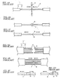
- Figures 4A to 4C and 5A to 5C show methods of decreasing a diameter increment of the above-mentioned spliced end.
- Figures 4A to 4C shows examples of splicing fibers and Figs. 5A to 5D shows those of multiple fibers.
- bare glass fibers 2 are exposed by removing the coating portion 3 of a pair of optical fibers 1 to be spliced together, and the splicing end 4 of each fiber is disposed to face that of other fiber at a predetermined space between them. Then the splicing ends 4 of both fibers 1 are heated and fused by arc discharge from an electrode 5. If each optical fiber 1 is pushed toward the other fiber and then fusion-spliced, there is produced a thick portion 7 at a junction 6, as shown in Fig. 4B. While the junction 6 is still softened due to high temperature, one or both of the fibers are pulled back to the opposite direction, and thereby the diameter of the thick portion 7 is decreased to produce a thin portion 8 as shown in Fig. 4C.
- the coating portions 3 of pairs of multiple fibers 1' are removed at and near splicing ends 4 to expose bare fiber portions 2 and the splicing ends 4 of the multiple fibers 1' are disposed to face one another.
- the splicing ends 4 are heated and fused by an arc discharge or the like, and then spliced as shown in Fig. 5B by pushing one or both pairs of the multiple fibers 1' toward the opposing multiple fibers by a predetermined length, respectively.
- the above Patent No. 2572978 discloses that the splicing loss can be suppressed to not more than 0.1 dB by making the ratio d/D (the ratio of the outer diameter 'd' of the thick portion 7 or thin portion 8 to the outer diameter of the bare fiber 'D') to be 0.95 to 1.18. Also disclosed therein is that the fibers are pulled back upon fusion splicing thereof for a time determined beforehand by the relation between the above d/D ratio and pulling-back time.
- the technology disclosed in the above prior art is for splicing single mode fibers having the same MFD, and no disclosure is made on splicing optical fibers having different MFDs.
- a method of reducing splicing loss in which the fusion-spliced portion of fibers having different MFDs are elongated so that the diameter of the bare fiber is reduced so as to obtain a reduced splicing loss.
- MFDs coincide by reducing the outer diameter of the bare fibers without applying the TEC treatment.
- the splicing loss of two splicing portions is from 3.8 dB before the elongation to 0.5 dB after the elongation. While it is a considerable improvement of the splicing loss, 0.5 dB cannot be said to be a low splicing loss.
- the splicing loss of GeO 2 doped SMFs is desirably not more than 0.1 dB. Further, in splicing multiple fibers en bloc, scattering of the pushing amount is unavoidable, and so it is difficult to reduce the splicing loss to not more than 0.1 dB by this method.
- the object of the present invention is to provide a method of splicing optical fibers at a low splicing loss and an optical component incorporating the fibers thus spliced at low loss.
- a new splicing method for optical fibers having different MFDs is provided.
- optical fibers having different MFDs are fusion-spliced, and additional heat treatment is applied to the fusion-spliced portion such that a dopant contained in the core portion is thermally diffused so as to cause the MFDs of the fibers to coincide each other.
- pairs of opposing fibers disposed in parallel in line or in the form of a ribbon are pushed in a longitudinal direction from one or both sides of the pairs toward the opposed fibers at the time of fusion-splicing, and then pulled back in the opposite direction to decrease the diameter increment in the fusion-spliced portions, which are subsequently subjected to the additional heat treatment.
- This multi-fiber component includes optical fibers having different MFDs which are fusion-spliced and the spliced portion is subjected to additional heat treatment such that a dopant contained in the core portion is thermally diffused, thereby causing the MFDs of the optical fibers to coincide, wherein the diameter increment of the spliced portion after the additional heating is not more than 11 ⁇ m
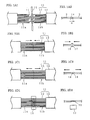
- Multi-fiber ribbons 11 comprise a plurality of optical fibers that are disposed in parallel in line. Each of multiple fibers 11a on one side of splicing pairs has an MFD of approximately 5 ⁇ m in a core portion of a bare fiber section 12. Multiple fiber 11b on the other side consist of GeO 2 doped single mode fibers (SMFs) having an MFD of approximately 10 ⁇ m in a core portion of a bare fiber section 12, respectively.
- SMFs GeO 2 doped single mode fibers
- a fiber coating portion 13 is removed at the splicing end portions of the multiple fibers 11a and 11b having different MFDs, so that a bare fiber 12 is exposed, respectively.
- Splicing ends 14 of the bare fiber portions 12 are cut to predetermined lengths.
- a thick portion 17 is produced in a splicing portion 16.
- the diameter increment in the thick portion 17 is larger if the space 'c' between the splicing ends is smaller and the pushing amount larger, and is smaller if the space 'c' is larger and the pushing amount smaller.
- the diameter increment in the thick portion affects the splicing loss decrement by the TEC treatment that is subsequently conducted. Therefore, it is necessary to limit the increment to a predetermined value.
- the multiple fibers are, subsequent to the pushing operation, pulled back in the opposite direction by a predetermined length as shown in Figs. 1C1 and 1C2.
- this pulling-back operation is conducted while the fusion-spliced portion 16 is softened at high temperature, it is possible to decrease the diameter of the thick portion 17, or to produce a thin portion 18, the outer diameter of which is smaller than that of the bare fiber 12.
- an additional heating for TEC treatment is conducted, as shown in Figs. 1D1 and 1D2.
- the additional heating is conducted by using an electric heater or a gas burner 19. All of the multiple fibers 11 are heated uniformly at a TEC treatment region 20 for a pre-determined time. With this additional heat treatment, a dopant contained in the core portion of the fibers is thermally diffused to the cladding portion so that different MFDs of the multiple fiber 11a and 11b coincide at the spliced-portion thereof and thereby the splicing loss can be substantially reduced.
- Figures 2A and 2B are figures for explaining the definition of diameter increment
- Fig. 2C is a graph showing the relation between diameter increment and splicing loss after TEC treatment.
- Figure 2C is a graph showing the relation between the diameter increment and splicing loss after TEC treatment, when fusion-splicing is done between two optical fibers having MFDs of 4 ⁇ m and 10 ⁇ m, respectively, and both having the outer diameter of bare fiber of 125 ⁇ m.
- Figure 2C shows that it is necessary to limit the diameter increment to not more than 11 ⁇ m, in order to obtain an after-TEC-treatment splicing loss of not more than 0.1 dB, which is usually required for the splicing of SMFs. Further, it also shows it is necessary to make the diameter increment not more than 5 ⁇ m, in order to obtain a more desirable splicing loss of not more than 0.05 dB after the TEC treatment.
- the diameter increment is not less than - 6 ⁇ m.
- the cross section of the fiber including the increment becomes not more than 90% of the cross section corresponding to the initial outer diameter of 125 ⁇ m.
- the splicing loss in the fusion-splicing of multiple fiber s having different MFDs can be made not more than 0.1 dB, which is equivalent to that which is desirable for the splicing loss of SMFs.
- the splicing portion whose diameter increment thus having been reduced can be housed in an ordinary optical connector ferrule.
- Figures 3A to 3F are examples of multi-fiber component incorporating fibers fusion spliced in accordance with the splicing method mentioned above.
- the optical fiber component shown in Fig. 3A consists of a fiber ribbon 21 including optical fibers having a smaller MFD and a fiber ribbon 22 including optical fibers having an ordinary MFD, whose different MFDs have been matched by the TEC treatment applied to a fusion-spliced portion 16, after the fusion-splicing operation of both fiber ribbons en bloc.
- the fusion-spliced portion 16 is subjected to the TEC treatment after the fusion splicing has been made by the pushing operation and the pulling back operation to decrease the diameter increment, as previously mentioned.
- the diameter increment of the fusion-spliced portion be not more than 11 ⁇ m and more desirably not more than 5 ⁇ m. Further, it is desirably not less than -20 ⁇ m, and more desirably not less than -6 ⁇ m.
- the fusion-spliced portion 16 is mechanically protected and reinforced by a protection sleeve 23.
- the splicing loss of the spliced portion in this structure can be made not more than 0.1 dB which is equivalent to that of SMFs.
- the multi-fiber unit 21 consists of optical fibers each having, for example, an approximately 5 ⁇ m MFD, which are disposed in parallel in line in the form of a ribbon, or stranded and housed in a tube.
- the multi-fiber unit 22 consists of optical fibers each having, for example, an approximately 10 ⁇ m MFD, which are disposed in parallel in line in the form of a ribbon, or stranded and housed in a tube.
- Figure 3B shows an optical fiber component in which a multi-fiber connector 24 is attached to the multi-fiber ribbon 21 in the configuration of Fig. 3A.
- This optical fiber component enables easy connection between planar optical waveguides having small MFDs and SMFs.
- This optical fiber component enables connecting the multi-fiber unit 21, each fiber of which has a 5 ⁇ m MFD, pluggably to an optical transmission line consisting of SMFs by means of the single-fiber connectors 25.
- a multi-fiber connector can be used instead of the single optical fiber connectors.
- Figure 3D shows a component consisting of a combination of the structures shown in Figs. 3B and 3C; that is, the optical fiber component consists of an optical fiber ribbon 21, each fiber of which has a 5 ⁇ m MFD and to which a multi-fiber connector 24 is attached, and a plurality of fibers 22' to which the single-fiber connectors 25 are attached.
- This optical component can be used for pluggably connecting planar optical waveguides having a small MFD to an optical transmission line consisting of SMFs by means of optical connectors 25.
- Figure 3E is an optical fiber component consisting of a fiber ribbon 21 separated into discrete fibers 21' which have a 5 ⁇ m MFD and which are individually fusion-spliced to optical fibers 22a each having a 10 ⁇ m MFD and whose fusion spliced portions 16 are housed individually in single-fiber connectors 25.
- the fusion-spliced portions 16 are formed by the method similar to the example described with reference to Fig. 3A.
- a branched portion of the fiber ribbon 21 is supported by a branch sleeve 26 to maintain the branched position.
- This optical fiber component can be used for connecting an optical transmission line consisting of SMFs to the optical fiber ribbon 21 consisting of optical fibers having a 5 ⁇ m MFD, by using the optical connectors 25, which are pluggable.
- a multi-fiber optical connector can be used also in place of the single-fiber connectors 25.
- Figure 3F is an optical fiber component consisting of an optical fiber ribbon 21 to which a multi-fiber connector 24 is attached on the unbranched side thereof in the configuration of Fig. 3E.
- This enables easy pluggable connection by means of the connectors 25, between planar optical waveguides each having a MFD of 5 ⁇ m and an optical transmission line consisting of SMFs.
- the optical fiber ribbon 21 consisting of optical fibers having an MFD of 5 ⁇ m can be replaced by an optical fiber ribbon 22 consisting of SMFs, and the optical fibers 22a or fibers 22' can be replaced by the fibers having an MFD of 5 ⁇ m.
Applications Claiming Priority (2)
| Application Number | Priority Date | Filing Date | Title |
|---|---|---|---|
| JP2002080075A JP2003279787A (ja) | 2002-03-22 | 2002-03-22 | 異種光ファイバの接続方法および多心光ファイバ部品 |
| JP2002080075 | 2002-03-22 |
Publications (2)
| Publication Number | Publication Date |
|---|---|
| EP1347321A2 true EP1347321A2 (de) | 2003-09-24 |
| EP1347321A3 EP1347321A3 (de) | 2005-02-02 |
Family
ID=27785350
Family Applications (1)
| Application Number | Title | Priority Date | Filing Date |
|---|---|---|---|
| EP03006489A Withdrawn EP1347321A3 (de) | 2002-03-22 | 2003-03-21 | Verfahren zum Spleissen von optischen Fasern und Vielfachfaserkomponente |
Country Status (5)
| Country | Link |
|---|---|
| US (1) | US20030180016A1 (de) |
| EP (1) | EP1347321A3 (de) |
| JP (1) | JP2003279787A (de) |
| CN (1) | CN1447139A (de) |
| CA (1) | CA2422011A1 (de) |
Families Citing this family (13)
| Publication number | Priority date | Publication date | Assignee | Title |
|---|---|---|---|---|
| JP4729394B2 (ja) * | 2004-12-28 | 2011-07-20 | プレサイスゲージ株式会社 | 光部品の製造方法及び製造装置、並びに、光部品 |
| KR20060076205A (ko) * | 2004-12-28 | 2006-07-04 | 프레사이스 게이지 가부시키가이샤 | 광부품의 제조방법 및 제조장치, 및 광부품 |
| WO2015026843A1 (en) * | 2013-08-19 | 2015-02-26 | Adc Telecommunications, Inc. | Fiber optic connector, fiber optic connector and cable assembly, and methods for manufacturing |
| JP6170527B2 (ja) | 2014-12-26 | 2017-07-26 | Toto株式会社 | 光レセプタクル及び光トランシーバ |
| CN110178066A (zh) * | 2017-01-17 | 2019-08-27 | 康普技术有限责任公司 | 高产率和低损耗的用于将光学光纤耦合到光学芯片的方法 |
| US10429589B2 (en) * | 2017-02-07 | 2019-10-01 | Corning Incorporated | Optical fiber for silicon photonics |
| CN113568114A (zh) * | 2017-03-30 | 2021-10-29 | Toto株式会社 | 光插座及光收发器 |
| CN109827518B (zh) * | 2017-11-23 | 2021-09-28 | 桂林电子科技大学 | 纤维集成干涉仪并联结构三维空间分布式形变传感器 |
| CN109839080B (zh) * | 2017-11-24 | 2021-09-28 | 桂林电子科技大学 | 一种白光干涉式纤维集成扭转传感器 |
| CN109839071B (zh) * | 2017-11-24 | 2021-04-06 | 桂林电子科技大学 | 纤维集成干涉仪串联结构三维空间分布式形变传感器 |
| CN109839074B (zh) * | 2017-11-24 | 2021-06-29 | 桂林电子科技大学 | 一种白光干涉式纤维集成万向弯曲传感器 |
| US10663687B1 (en) * | 2018-12-14 | 2020-05-26 | Leviton Manufacturing Co., Inc. | Fiber optic pigtail assembly |
| CN109856721A (zh) * | 2019-03-28 | 2019-06-07 | 浙江大学 | 一种微纳光纤的批量制备装置及方法 |
Citations (4)
| Publication number | Priority date | Publication date | Assignee | Title |
|---|---|---|---|---|
| JPS63167310A (ja) * | 1986-12-27 | 1988-07-11 | Fujikura Ltd | 多心光フアイバの接続方法 |
| EP0340042A1 (de) * | 1988-04-29 | 1989-11-02 | BRITISH TELECOMMUNICATIONS public limited company | Verbinden von optischen Wellenleitern |
| JPH0284604A (ja) * | 1988-09-21 | 1990-03-26 | Sumitomo Electric Ind Ltd | 多心光ファイバの融着接続方法 |
| JPH03238404A (ja) * | 1990-02-15 | 1991-10-24 | Nec Corp | 光ファイバスプライシング方法 |
Family Cites Families (2)
| Publication number | Priority date | Publication date | Assignee | Title |
|---|---|---|---|---|
| US6565269B2 (en) * | 2001-02-07 | 2003-05-20 | Fitel Usa Corp. | Systems and methods for low-loss splicing of optical fibers having a high concentration of fluorine to other types of optical fiber |
| WO2002103404A2 (en) * | 2001-06-15 | 2002-12-27 | Corning Incorporated | Tapered lensed fiber for focusing and condenser applications |
-
2002
- 2002-03-22 JP JP2002080075A patent/JP2003279787A/ja active Pending
-
2003
- 2003-03-13 CA CA002422011A patent/CA2422011A1/en not_active Abandoned
- 2003-03-17 US US10/388,613 patent/US20030180016A1/en not_active Abandoned
- 2003-03-21 EP EP03006489A patent/EP1347321A3/de not_active Withdrawn
- 2003-03-21 CN CN03107620.3A patent/CN1447139A/zh active Pending
Patent Citations (4)
| Publication number | Priority date | Publication date | Assignee | Title |
|---|---|---|---|---|
| JPS63167310A (ja) * | 1986-12-27 | 1988-07-11 | Fujikura Ltd | 多心光フアイバの接続方法 |
| EP0340042A1 (de) * | 1988-04-29 | 1989-11-02 | BRITISH TELECOMMUNICATIONS public limited company | Verbinden von optischen Wellenleitern |
| JPH0284604A (ja) * | 1988-09-21 | 1990-03-26 | Sumitomo Electric Ind Ltd | 多心光ファイバの融着接続方法 |
| JPH03238404A (ja) * | 1990-02-15 | 1991-10-24 | Nec Corp | 光ファイバスプライシング方法 |
Non-Patent Citations (3)
| Title |
|---|
| PATENT ABSTRACTS OF JAPAN vol. 012, no. 436 (P-787), 17 November 1988 (1988-11-17) -& JP 63 167310 A (FUJIKURA LTD), 11 July 1988 (1988-07-11) * |
| PATENT ABSTRACTS OF JAPAN vol. 014, no. 283 (P-1063), 19 June 1990 (1990-06-19) -& JP 02 084604 A (SUMITOMO ELECTRIC IND LTD; others: 01), 26 March 1990 (1990-03-26) * |
| PATENT ABSTRACTS OF JAPAN vol. 016, no. 024 (P-1301), 21 January 1992 (1992-01-21) -& JP 03 238404 A (NEC CORP), 24 October 1991 (1991-10-24) * |
Also Published As
| Publication number | Publication date |
|---|---|
| JP2003279787A (ja) | 2003-10-02 |
| EP1347321A3 (de) | 2005-02-02 |
| CA2422011A1 (en) | 2003-09-22 |
| CN1447139A (zh) | 2003-10-08 |
| US20030180016A1 (en) | 2003-09-25 |
Similar Documents
| Publication | Publication Date | Title |
|---|---|---|
| US6275627B1 (en) | Optical fiber having an expanded mode field diameter and method of expanding the mode field diameter of an optical fiber | |
| EP1060423B1 (de) | Optische koppler für multimodefasern | |
| US6652163B2 (en) | Splice joint and process for joining a microstructured optical fiber and a conventional optical fiber | |
| EP2033277B1 (de) | Vorrichtung für die ankopplung von strahlung in oder aus einer optischen faser | |
| US5588087A (en) | Overlapping fusion attenuator | |
| EP1347321A2 (de) | Verfahren zum Spleissen von optischen Fasern und Vielfachfaserkomponente | |
| EP1659428A1 (de) | Filteroptik-übertragungsleitung | |
| CA2441918C (en) | Optical coupler comprising multimode fibers and method of making the same | |
| US7037004B2 (en) | Optical fiber component for spot size transition and method of making the same | |
| EP1219987B1 (de) | Spleissverfahren von optischen Fasern | |
| JP3746619B2 (ja) | 光ファイバの融着接続方法 | |
| CN109983379B (zh) | 光纤线路和光纤线路制造方法 | |
| US20190331868A1 (en) | Methods for coupling optical fibers to optical chips with high yield and low-loss | |
| JP2005043442A (ja) | 光ファイバの接続構造及び光接続部材並びに光コネクタ | |
| JP2619130B2 (ja) | シングルモード光ファイバの相互接続方法 | |
| JP3355575B2 (ja) | 単一モード光ファイバ及び単一モード光ファイバのコア拡大方法 | |
| JPH0789164B2 (ja) | 光ファイバ・モード整合器 | |
| JP2004163747A (ja) | 光ファイバの接続方法 | |
| JP2000206361A (ja) | 光ファイバ型多分岐カプラ―及びその製造方法 | |
| JP2003302550A (ja) | ケーブル接続方法及び光ファイバ接続部材 |
Legal Events
| Date | Code | Title | Description |
|---|---|---|---|
| PUAI | Public reference made under article 153(3) epc to a published international application that has entered the european phase |
Free format text: ORIGINAL CODE: 0009012 |
|
| AK | Designated contracting states |
Kind code of ref document: A2 Designated state(s): AT BE BG CH CY CZ DE DK EE ES FI FR GB GR HU IE IT LI LU MC NL PT SE SI SK TR |
|
| AX | Request for extension of the european patent |
Extension state: AL LT LV MK RO |
|
| PUAL | Search report despatched |
Free format text: ORIGINAL CODE: 0009013 |
|
| AK | Designated contracting states |
Kind code of ref document: A3 Designated state(s): AT BE BG CH CY CZ DE DK EE ES FI FR GB GR HU IE IT LI LU MC NL PT SE SI SK TR |
|
| AX | Request for extension of the european patent |
Extension state: AL LT LV MK RO |
|
| 17P | Request for examination filed |
Effective date: 20050802 |
|
| AKX | Designation fees paid |
Designated state(s): DE FR GB IT |
|
| STAA | Information on the status of an ep patent application or granted ep patent |
Free format text: STATUS: THE APPLICATION IS DEEMED TO BE WITHDRAWN |
|
| 18D | Application deemed to be withdrawn |
Effective date: 20060106 |