EP1347234A2 - Leuchtsystem - Google Patents
Leuchtsystem Download PDFInfo
- Publication number
- EP1347234A2 EP1347234A2 EP03005078A EP03005078A EP1347234A2 EP 1347234 A2 EP1347234 A2 EP 1347234A2 EP 03005078 A EP03005078 A EP 03005078A EP 03005078 A EP03005078 A EP 03005078A EP 1347234 A2 EP1347234 A2 EP 1347234A2
- Authority
- EP
- European Patent Office
- Prior art keywords
- lighting system
- bore
- mechanical holder
- transparent element
- light source
- Prior art date
- Legal status (The legal status is an assumption and is not a legal conclusion. Google has not performed a legal analysis and makes no representation as to the accuracy of the status listed.)
- Granted
Links
Images

Classifications
-
- F—MECHANICAL ENGINEERING; LIGHTING; HEATING; WEAPONS; BLASTING
- F21—LIGHTING
- F21V—FUNCTIONAL FEATURES OR DETAILS OF LIGHTING DEVICES OR SYSTEMS THEREOF; STRUCTURAL COMBINATIONS OF LIGHTING DEVICES WITH OTHER ARTICLES, NOT OTHERWISE PROVIDED FOR
- F21V5/00—Refractors for light sources
- F21V5/06—Hanging lustres for chandeliers
-
- F—MECHANICAL ENGINEERING; LIGHTING; HEATING; WEAPONS; BLASTING
- F21—LIGHTING
- F21V—FUNCTIONAL FEATURES OR DETAILS OF LIGHTING DEVICES OR SYSTEMS THEREOF; STRUCTURAL COMBINATIONS OF LIGHTING DEVICES WITH OTHER ARTICLES, NOT OTHERWISE PROVIDED FOR
- F21V21/00—Supporting, suspending, or attaching arrangements for lighting devices; Hand grips
- F21V21/34—Supporting elements displaceable along a guiding element
- F21V21/35—Supporting elements displaceable along a guiding element with direct electrical contact between the supporting element and electric conductors running along the guiding element
-
- F—MECHANICAL ENGINEERING; LIGHTING; HEATING; WEAPONS; BLASTING
- F21—LIGHTING
- F21V—FUNCTIONAL FEATURES OR DETAILS OF LIGHTING DEVICES OR SYSTEMS THEREOF; STRUCTURAL COMBINATIONS OF LIGHTING DEVICES WITH OTHER ARTICLES, NOT OTHERWISE PROVIDED FOR
- F21V23/00—Arrangement of electric circuit elements in or on lighting devices
- F21V23/06—Arrangement of electric circuit elements in or on lighting devices the elements being coupling devices, e.g. connectors
-
- F—MECHANICAL ENGINEERING; LIGHTING; HEATING; WEAPONS; BLASTING
- F21—LIGHTING
- F21W—INDEXING SCHEME ASSOCIATED WITH SUBCLASSES F21K, F21L, F21S and F21V, RELATING TO USES OR APPLICATIONS OF LIGHTING DEVICES OR SYSTEMS
- F21W2121/00—Use or application of lighting devices or systems for decorative purposes, not provided for in codes F21W2102/00 – F21W2107/00
-
- F—MECHANICAL ENGINEERING; LIGHTING; HEATING; WEAPONS; BLASTING
- F21—LIGHTING
- F21Y—INDEXING SCHEME ASSOCIATED WITH SUBCLASSES F21K, F21L, F21S and F21V, RELATING TO THE FORM OR THE KIND OF THE LIGHT SOURCES OR OF THE COLOUR OF THE LIGHT EMITTED
- F21Y2115/00—Light-generating elements of semiconductor light sources
- F21Y2115/10—Light-emitting diodes [LED]
-
- H—ELECTRICITY
- H01—ELECTRIC ELEMENTS
- H01R—ELECTRICALLY-CONDUCTIVE CONNECTIONS; STRUCTURAL ASSOCIATIONS OF A PLURALITY OF MUTUALLY-INSULATED ELECTRICAL CONNECTING ELEMENTS; COUPLING DEVICES; CURRENT COLLECTORS
- H01R25/00—Coupling parts adapted for simultaneous co-operation with two or more identical counterparts, e.g. for distributing energy to two or more circuits
- H01R25/14—Rails or bus-bars constructed so that the counterparts can be connected thereto at any point along their length
- H01R25/147—Low voltage devices, i.e. safe to touch live conductors
-
- Y—GENERAL TAGGING OF NEW TECHNOLOGICAL DEVELOPMENTS; GENERAL TAGGING OF CROSS-SECTIONAL TECHNOLOGIES SPANNING OVER SEVERAL SECTIONS OF THE IPC; TECHNICAL SUBJECTS COVERED BY FORMER USPC CROSS-REFERENCE ART COLLECTIONS [XRACs] AND DIGESTS
- Y10—TECHNICAL SUBJECTS COVERED BY FORMER USPC
- Y10S—TECHNICAL SUBJECTS COVERED BY FORMER USPC CROSS-REFERENCE ART COLLECTIONS [XRACs] AND DIGESTS
- Y10S362/00—Illumination
- Y10S362/806—Ornamental or decorative
Definitions
- the present invention relates to a lighting system with at least one or at least one Decorative transparent element having a bore, with at least one light source for lighting the at least one decorative transparent element and with a mechanical, reaching into the hole holder for holding or hanging the at least one decorative transparent element.
- Lighting systems with a decorative, transparent element for example in the form of a Jewelery has been known for a long time. Placing a light source on or in decorative, transparent element increases its aesthetic appeal through the Multiple reflections and refractions from the decorative, transparent element emerging light.
- Decorative lighting systems are available in many different designs.
- the US For example, 5,653,530 discloses a lighting system in which the light source is in one connected to the decorative, transparent element by a wire opaque version.
- US 5,876,109 describes a lighting system a decorative, transparent element in the form of a piece of jewelry, in which in a A light source is arranged for this purpose. The bracket is outside the hole.
- the object of the invention is a structurally simple and visually appealing Create lighting system.
- An advantageous embodiment of the invention results from the fact that the light source an LED is selected. This combines a compact design and a large one Luminosity with low power consumption.
- Another advantageous embodiment of the invention results from the fact that a LED sunk into a recess provided in the hole located part of the mechanical bracket is attached. This enables placement a light source in a decorative, transparent one that was not originally designed for it Element.
- Another advantageous embodiment of the invention results from the fact that decorative, transparent element of the lighting system has several blind holes, in which can each be attached to a light emitting diode. This allows the uniform interior Illumination of larger decorative, transparent elements.
- Another advantageous embodiment of the invention results from the fact that the mechanical mounting of the lighting system in the area of the decorative, transparent Element is designed in the form of two spring-loaded brackets, one non-positive determination of the light sources loosely inserted in the respective hole allow. This results in a particularly high level of user friendliness due to the Possibility to quickly replace defective light sources.
- the mechanical holder at least largely made of glass fiber reinforced plastic, preferably epoxy. This creates a mechanical bracket with favorable mechanical properties realized with low weight.
- Another advantageous embodiment of the invention results from the fact that the mechanical holder in the area of the decorative, transparent element as an elongated Bracket is executed. This allows multiple light sources to be placed in the same Drilling.
- Another advantageous embodiment of the invention results from the fact that the mechanical holder on two opposite sides over the entire length is at least partially covered with an electrically conductive layer.
- the presence conductive layers allows the wireless power supply from the mechanical Bracket contacted light sources, which is aesthetically advantageous.
- Another advantageous embodiment of the invention results from the fact that the mechanical holder in the area of the free end facing away from the bore Hanger is formed and the hanger has electrically conductive contact surfaces that are each connected to a conductive layer.
- This allows the lighting system to be connected to one arbitrarily shaped busbar can be detachably suspended, the gravity as Pressure force acts and a complex screwing or jamming of the Makes lighting systems on the busbar unnecessary. Avoiding a technical complex connection of the lighting system with an external power source leads to a low susceptibility to failure.
- This embodiment is particularly advantageous Possibility of multiple lighting systems at freely selectable locations on the same track to arrange.
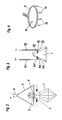
- Fig. 1 shows a lighting system 10 with a decorative, transparent element 1 in the form a chandelier curtain with a substantially horizontal (Through) bore 2 is provided, through which it is on a rigid mechanical Bracket 3 is detachably suspended.
- Am in the continuously cylindrical bore 2 located part 3 'of the mechanical bracket 3 is in a recess 5 LED 4 sunk attached.
- the power is supplied via the on the side surfaces 3a, 3b of the mechanical holder 3 located conductive layers 6a, 6b (see Fig. 1a), which extend over the entire length of the bracket 3 and on the on the busbar facing side of the upper region 3 "designed as a hanger, the Bracket 3 in each other at an angle opposite contact surfaces 7a, 7b open out (see Fig.
- Fig. 1d shows a detailed view of the recess 5, on which the Contacting the different poles 4a, 4b as in this embodiment LED light source 4 is recognizable.
- Fig. 2 shows a further embodiment of the invention.
- the LED 4 loose in the through hole 2 of the decorative, transparent element 1 is introduced and then through in the area of the decorative, transparent element 1 designed as a spring-loaded clamp 9 mechanical holder 3 is contacted electrically from both sides of the bore 2, whereby the circuit over the LED 4 is closed.
- FIG. 3 shows a further exemplary embodiment of a lighting system 10 according to the invention, in which there are two LEDs 4 ⁇ , 4 ⁇ in mutually opposite blind holes 2 ⁇ , 2 ⁇ and the power supply to the LEDs 4 ⁇ , 4 ⁇ by the respective mechanical bracket 3 ⁇ , 3 ⁇ .
- FIG. 4 shows an application example in which a plurality of lighting systems 10 according to the invention are detachably suspended from an annular busbar 8.
- the invention is of course not based on the illustrated embodiments limited. Rather, it can in particular be provided that a possibly colored light bulb is used that is the decorative, transparent Element designed in the form of a piece of jewelry that is decorative, transparent Element has both through holes and blind holes that on one mechanical holder several decorative, transparent elements are arranged or that the decorative, transparent element has its own color.
Landscapes
- Engineering & Computer Science (AREA)
- General Engineering & Computer Science (AREA)
- Non-Portable Lighting Devices Or Systems Thereof (AREA)
Abstract
Description
Claims (25)
- Leuchtsystem mit mindestens einem wenigstens eine Bohrung aufweisenden dekorativen transparenten Element, mit wenigstens einer Lichtquelle zur Beleuchtung des mindestens einen dekorativen transparenten Elements und mit einer mechanischen, in die Bohrung reichenden Halterung zum Halten bzw. Aufhängen des mindestens einen dekorativen transparenten Elements, dadurch gekennzeichnet, dass die Lichtquelle(n) (4) in der bzw. den Bohrung(en) (2) des bzw. der dekorativen transparenten Elemente(s) (1) angeordnet ist (sind) und die Stromzufuhr zu der bzw. den Lichtquelle(n) (4) über die jeweilige Halterung (3) erfolgt.
- Leuchtsystem nach Anspruch 1, dadurch gekennzeichnet, dass zumindest eine Lichtquelle (4) eine Leuchtdiode (LED) ist.
- Leuchtsystem nach Anspruch 1 oder 2, dadurch gekennzeichnet, dass die Lichtquelle(n) (4) an der jeweiligen Halterung (3) befestigt ist (sind).
- Leuchtsystem nach Anspruch 1 oder 2, dadurch gekennzeichnet, dass die Lichtquelle(n) (4) lose in die Bohrung(en) (2) eingesetzt ist (sind) und die jeweilige stromführende Halterung (3) die Lichtquelle(n) (4) bzw. deren Fassung(en) elektrisch kontaktiert.
- Leuchtsystem nach einem der Ansprüche 1 bis 4, dadurch gekennzeichnet, dass zumindest ein Teil der Bohrung(en) (2) als Durchgangsbohrung(en) ausgeführt ist (sind).
- Leuchtsystem nach einem der Ansprüche 1 bis 5, dadurch gekennzeichnet, dass zumindest ein Teil der Bohrung(en) (2) als Sackbohrung(en) ausgeführt ist (sind).
- Leuchtsystem nach Anspruch 6, dadurch gekennzeichnet, dass sich zwei Sackbohrungen annähernd gegenüberliegen.
- Leuchtsystem nach einem der Ansprüche 1 bis 7, dadurch gekennzeichnet, dass die Bohrung(en) (2) einen Durchmesser kleiner als 5 mm, vorzugsweise kleiner als 2 mm hat (haben).
- Leuchtsystem nach einem der Ansprüche 1 bis 8, dadurch gekennzeichnet, dass das dekorative transparente Element (1) ein facettierter Glaskörper ist.
- Leuchtsystem nach einem der Ansprüche 1 bis 8, dadurch gekennzeichnet, dass das dekorative transparente Element (1) ein Lusterbehang ist.
- Leuchtsystem nach einem der Ansprüche 1 bis 8, dadurch gekennzeichnet, dass das dekorative transparente Element (1) ein Schmuckstück ist.
- Leuchtsystem nach einem der Ansprüche 1 bis 11, dadurch gekennzeichnet, dass die Bohrung(en) (2) des bzw. der dekorativen transparenten Elemente(s) (1) in montierten Zustand in eine im wesentlichen horizontale Richtung verläuft (verlaufen).
- Leuchtsystem nach einem der Ansprüche 1 bis 12, dadurch gekennzeichnet, dass die Bohrung(en) (2) des bzw. der dekorativen transparenten Elemente(s) (1) zylindrisch ist (sind) und konstanten Durchmesser aufweist (aufweisen).
- Leuchtsystem nach einem der Ansprüche 1 bis 13, dadurch gekennzeichnet, dass die Halterung (3) lösbar in die Bohrung(en) (2) einsetzbar ist.
- Mechanische Halterung eines dekoratives transparentes Element eines Leuchtsystems nach einem der Ansprüche 1 bis 14.
- Mechanische Halterung nach Anspruch 15, dadurch gekennzeichnet, dass sie in sich starr ausgebildet ist.
- Mechanische Halterung nach Anspruch 15 oder 16, dadurch gekennzeichnet, dass die mechanische Halterung (3) großteils aus verstärktem Kunststoff, vorzugsweise aus glasfaserverstärktem Kunststoff, vorzugsweise Expoxidmaterial, besteht.
- Mechanische Halterung nach einem der Ansprüche 15 bis 17, dadurch gekennzeichnet, dass der in die Bohrung (2) des dekorativen transparenten Elementes (1) reichende Teil (3') der mechanischen Halterung (3) als länglicher Bügel ausgebildet ist.
- Mechanische Halterung nach Anspruch 18, dadurch gekennzeichnet, dass der Bügel (3') mindestens eine Aussparung (5) aufweist, in der jeweils wenigstens eine Leuchtquelle (4) angebracht ist.
- Mechanische Halterung nach einem der Ansprüche 15 bis 19, dadurch gekennzeichnet, dass die mechanische Halterung (3) an zwei sich gegenüberliegenden Seiten (3a, 3b) über die gesamte Länge zumindest teilweise mit einer elektrisch leitenden Schicht (6a, 6b) bedeckt ist.
- Mechanische Halterung nach Anspruch 20, dadurch gekennzeichnet, dass eine elektrisch leitende Schicht (6a) mit einem Pol (4a) der Leuchtquelle (4) und die andere elektrisch leitende Schicht (6b) mit dem anderen Pol (4b) der Leuchtquelle (4) verbunden ist.
- Mechanische Halterung nach einem der Ansprüche 15 bis 21, dadurch gekennzeichnet, dass die mechanische Halterung (3) im Bereich des der Bohrung (2) abgewandten, freien Endes (3") als Aufhänger ausgeformt ist.
- Mechanische Halterung nach einem der Ansprüche 15 bis 21, dadurch gekennzeichnet, dass der Aufhänger (3") elektrisch leitende Kontaktflächen (7a, 7b) aufweist, die mit einer Stromschiene (8) oder dergleichen lösbar verbindbar sind.
- Mechanische Halterung nach Anspruch 23, dadurch gekennzeichnet, dass eine der Kontaktflächen (7a) mit der elektrisch leitenden Schicht (6a) auf der einen Seite (3a) der mechanischen Halterung (3) und eine andere Kontaktfläche (7b) mit der elektrisch leitenden Schicht (6b) auf der gegenüberliegenden Seite (3b) der mechanischen Halterung (3) verbunden ist.
- Mechanische Halterung nach Anspruch 24, dadurch gekennzeichnet, dass der Aufhänger (3") so auf einer, aus beidseitig einer Isolatorschicht angeordneten, auf unterschiedlichem elektrischem Potential gehaltenen Flächen (8a, 8b) bestehenden, Stromschiene (8) lagerbar ist, dass die Schwerkraft als Andruckkraft wirkt, und eine Kontaktfläche (7a) an die eine auf einem Potential liegende Fläche (8a) der Stromschiene (8) gedrückt wird und eine weitere Kontaktfläche (7b) an die auf einem unterschiedlichem Potential liegende andere Fläche (8b) der Stromschiene (8) gedrückt wird.
Applications Claiming Priority (2)
| Application Number | Priority Date | Filing Date | Title |
|---|---|---|---|
| AT0044402A AT412117B (de) | 2002-03-22 | 2002-03-22 | Leuchtsystem |
| AT4442002 | 2002-03-22 |
Publications (3)
| Publication Number | Publication Date |
|---|---|
| EP1347234A2 true EP1347234A2 (de) | 2003-09-24 |
| EP1347234A3 EP1347234A3 (de) | 2006-01-11 |
| EP1347234B1 EP1347234B1 (de) | 2014-11-19 |
Family
ID=27768012
Family Applications (1)
| Application Number | Title | Priority Date | Filing Date |
|---|---|---|---|
| EP03005078.5A Expired - Lifetime EP1347234B1 (de) | 2002-03-22 | 2003-03-07 | Leuchtsystem |
Country Status (4)
| Country | Link |
|---|---|
| US (1) | US7018083B2 (de) |
| EP (1) | EP1347234B1 (de) |
| AT (1) | AT412117B (de) |
| ES (1) | ES2529670T3 (de) |
Cited By (1)
| Publication number | Priority date | Publication date | Assignee | Title |
|---|---|---|---|---|
| ITPD20090050A1 (it) * | 2009-03-17 | 2010-09-18 | Dacrilux Di Boscolo Claudio | Struttura di supporto per pendagli decorativi, applicabile in particolare su dispositivi di illuminazione |
Families Citing this family (1)
| Publication number | Priority date | Publication date | Assignee | Title |
|---|---|---|---|---|
| US7261444B2 (en) * | 2004-02-05 | 2007-08-28 | Schonbek Worldwide Lighting, Inc. | Arrangements and methods for connecting decorative ornaments |
Citations (2)
| Publication number | Priority date | Publication date | Assignee | Title |
|---|---|---|---|---|
| US5653530A (en) | 1995-11-08 | 1997-08-05 | Pittman; Rusty M. | Ornamental lighting device |
| US5876109A (en) | 1997-09-26 | 1999-03-02 | Scalco; Vincent James | Lighted jewelry ornaments |
Family Cites Families (27)
| Publication number | Priority date | Publication date | Assignee | Title |
|---|---|---|---|---|
| DE1189488B (de) * | 1962-02-07 | 1965-03-25 | Erwin Knoll | Leuchtkristall |
| NL6903726A (de) | 1969-03-11 | 1970-09-15 | ||
| US3820201A (en) * | 1973-04-02 | 1974-06-28 | Crystalon Sa | Link construction for a crystal pendant |
| US3968357A (en) * | 1975-10-29 | 1976-07-06 | Lawrence Peska Associates, Inc. | Illuminated earring which is switched on by securement to the ear |
| US4271457A (en) * | 1979-03-20 | 1981-06-02 | Martin Danny W | Intermittent light circuit body movement actuated jewelry |
| JPH0127213Y2 (de) * | 1985-02-18 | 1989-08-15 | ||
| US4912609A (en) * | 1988-10-31 | 1990-03-27 | Gillette Kenneth R | Personalized night-light |
| FR2660048B3 (fr) * | 1990-03-22 | 1992-07-17 | Rondinaud Alain | Dispositif d'eclairage mobile a fixer a une paroi verticale. |
| FR2671471A1 (fr) * | 1991-01-15 | 1992-07-17 | Bancel Guy | Dispositif pour l'accrochage mural d'un objet, notamment d'un tableau. |
| GB2253129A (en) * | 1991-02-27 | 1992-09-02 | Edward Ernest Sheed | Illuminated jewellery |
| US5274537A (en) * | 1992-04-06 | 1993-12-28 | Richard G. Altman | Decorative lighting arrangement for special events |
| US5311417A (en) * | 1993-08-23 | 1994-05-10 | Heh Mao Lin | Illuminative sucker & decorative string thereof |
| US5477433A (en) * | 1994-04-01 | 1995-12-19 | Ohlund; Stephen K. | Illuminated necklace |
| US5685635A (en) * | 1994-09-21 | 1997-11-11 | Barcana, Inc. | Decorative lighting system for indoor and outdoor use |
| US5704704A (en) * | 1995-04-10 | 1998-01-06 | Attwood Corporation | Marine pole light and base |
| US5911501A (en) * | 1996-12-23 | 1999-06-15 | Empire Industries, Inc. | Home decoration system |
| US6122933A (en) * | 1998-08-14 | 2000-09-26 | Ohlund; Stephen K. | Jewelry piece |
| US6233971B1 (en) * | 1998-08-14 | 2001-05-22 | Calypso Worldwide Marketing, Inc. | Jewelry piece |
| US6086220A (en) * | 1998-09-30 | 2000-07-11 | Lash International Inc. | Marine safety light |
| US6578981B2 (en) * | 1999-11-09 | 2003-06-17 | Big Easy Beads, Llc | Lighted bead necklace |
| US6601965B2 (en) * | 2000-02-04 | 2003-08-05 | Firejewel, Llc | Jewelry with battery-illuminated medallion |
| US6328457B1 (en) * | 2000-02-16 | 2001-12-11 | Ming Hsien Huang | Combo type garden lamp structure |
| CA2337711A1 (en) * | 2000-02-23 | 2001-08-23 | Keith Charles Jantz | Electrically powered element and a battery therefor |
| FR2809159A1 (fr) * | 2000-03-06 | 2001-11-23 | Alain Minville | Cymaise electrique polyvalente |
| DE20017577U1 (de) * | 2000-10-13 | 2001-01-04 | Shining Blick Enterprises Co., Ltd., Taipeh/T'ai-pei | Schutz- und Schmuckstruktur für kolbenartige Glühbirnen ohne Halterung |
| US20020159256A1 (en) * | 2001-04-25 | 2002-10-31 | Ming-Hsiung Chen | Detachable christmas ornamental ball |
| US6659616B1 (en) * | 2002-08-09 | 2003-12-09 | Dayva International | Lighting structure for patio umbrella |
-
2002
- 2002-03-22 AT AT0044402A patent/AT412117B/de not_active IP Right Cessation
-
2003
- 2003-03-07 EP EP03005078.5A patent/EP1347234B1/de not_active Expired - Lifetime
- 2003-03-07 ES ES03005078.5T patent/ES2529670T3/es not_active Expired - Lifetime
- 2003-03-20 US US10/391,553 patent/US7018083B2/en not_active Expired - Lifetime
Patent Citations (2)
| Publication number | Priority date | Publication date | Assignee | Title |
|---|---|---|---|---|
| US5653530A (en) | 1995-11-08 | 1997-08-05 | Pittman; Rusty M. | Ornamental lighting device |
| US5876109A (en) | 1997-09-26 | 1999-03-02 | Scalco; Vincent James | Lighted jewelry ornaments |
Cited By (1)
| Publication number | Priority date | Publication date | Assignee | Title |
|---|---|---|---|---|
| ITPD20090050A1 (it) * | 2009-03-17 | 2010-09-18 | Dacrilux Di Boscolo Claudio | Struttura di supporto per pendagli decorativi, applicabile in particolare su dispositivi di illuminazione |
Also Published As
| Publication number | Publication date |
|---|---|
| ES2529670T3 (es) | 2015-02-24 |
| EP1347234A3 (de) | 2006-01-11 |
| EP1347234B1 (de) | 2014-11-19 |
| AT412117B (de) | 2004-09-27 |
| US7018083B2 (en) | 2006-03-28 |
| US20030179568A1 (en) | 2003-09-25 |
| ATA4442002A (de) | 2004-02-15 |
Similar Documents
| Publication | Publication Date | Title |
|---|---|---|
| EP2151899B1 (de) | Lichtbandsystem | |
| DE202012103937U1 (de) | Längenverstellbare Leuchte, insbesondere Pendelleuchte | |
| EP1347234A2 (de) | Leuchtsystem | |
| EP2187485B1 (de) | Elektrische Steckdose | |
| EP0285627A1 (de) | Leuchtenanordnung mit zwischen zwei niederspannungs-stromleitern angeordneten leuchten. | |
| DE202017101703U1 (de) | Lichtelement, insbesondere für eine Lichterkette | |
| AT508337B1 (de) | Beleuchtungsvorrichtung | |
| DE202011103740U1 (de) | Lichterkette mit LED-Beleuchtung | |
| WO2005067769A1 (de) | Hohlkörperförmiges dekorationselement, insebesondere christbaumkugel | |
| DE9209490U1 (de) | Beleuchtungseinrichtung für ein Blumenaquarium | |
| EP0922904B1 (de) | Niedervolt-Pendelleuchte mit Gegengewicht | |
| DE20009450U1 (de) | Stromschienensystem | |
| DE102004054211B4 (de) | Niedervolt-Beleuchtungssystem | |
| DE29605993U1 (de) | Lichterkette bzw. Lichtband | |
| DE9304052U1 (de) | Schmuckgehänge | |
| DE202015107077U1 (de) | Pendelleuchte | |
| DE102009052003A1 (de) | Wand- oder Deckenleuchte | |
| DE29520982U1 (de) | Frei verformbares Hochvolt-Lichtstromschienensystem | |
| DE202008002583U1 (de) | Lichtkreuz | |
| DE102010018557B4 (de) | Beleuchtungsvorrichtung für stauberfüllte Räume | |
| DE102004044024A1 (de) | Vorrichtung zur hängenden Anordung einer Leuchte | |
| DE20003956U1 (de) | Beleuchtungsanordnung an volkskünstlerischen Schmuckgegenständen | |
| DE202004014148U1 (de) | Vorrichtung zur hängenden Anordnung | |
| DE202014102667U1 (de) | Leuchte | |
| DE29822249U1 (de) | Beleuchtungseinrichtung für einen Schirm |
Legal Events
| Date | Code | Title | Description |
|---|---|---|---|
| PUAI | Public reference made under article 153(3) epc to a published international application that has entered the european phase |
Free format text: ORIGINAL CODE: 0009012 |
|
| AK | Designated contracting states |
Kind code of ref document: A2 Designated state(s): AT BE BG CH CY CZ DE DK EE ES FI FR GB GR HU IE IT LI LU MC NL PT RO SE SI SK TR |
|
| AX | Request for extension of the european patent |
Extension state: AL LT LV MK |
|
| PUAL | Search report despatched |
Free format text: ORIGINAL CODE: 0009013 |
|
| AK | Designated contracting states |
Kind code of ref document: A3 Designated state(s): AT BE BG CH CY CZ DE DK EE ES FI FR GB GR HU IE IT LI LU MC NL PT RO SE SI SK TR |
|
| AX | Request for extension of the european patent |
Extension state: AL LT LV MK |
|
| 17P | Request for examination filed |
Effective date: 20060522 |
|
| AKX | Designation fees paid |
Designated state(s): AT BE BG CH CY CZ DE DK EE ES FI FR GB GR HU IE IT LI LU MC NL PT RO SE SI SK TR |
|
| 17Q | First examination report despatched |
Effective date: 20060919 |
|
| RAP1 | Party data changed (applicant data changed or rights of an application transferred) |
Owner name: D. SWAROVSKI KG |
|
| GRAP | Despatch of communication of intention to grant a patent |
Free format text: ORIGINAL CODE: EPIDOSNIGR1 |
|
| INTG | Intention to grant announced |
Effective date: 20140721 |
|
| GRAS | Grant fee paid |
Free format text: ORIGINAL CODE: EPIDOSNIGR3 |
|
| GRAA | (expected) grant |
Free format text: ORIGINAL CODE: 0009210 |
|
| AK | Designated contracting states |
Kind code of ref document: B1 Designated state(s): AT BE BG CH CY CZ DE DK EE ES FI FR GB GR HU IE IT LI LU MC NL PT RO SE SI SK TR |
|
| REG | Reference to a national code |
Ref country code: GB Ref legal event code: FG4D Free format text: NOT ENGLISH |
|
| REG | Reference to a national code |
Ref country code: CH Ref legal event code: EP |
|
| REG | Reference to a national code |
Ref country code: AT Ref legal event code: REF Ref document number: 697252 Country of ref document: AT Kind code of ref document: T Effective date: 20141215 |
|
| REG | Reference to a national code |
Ref country code: IE Ref legal event code: FG4D Free format text: LANGUAGE OF EP DOCUMENT: GERMAN |
|
| REG | Reference to a national code |
Ref country code: DE Ref legal event code: R096 Ref document number: 50315160 Country of ref document: DE Effective date: 20141231 |
|
| REG | Reference to a national code |
Ref country code: ES Ref legal event code: FG2A Ref document number: 2529670 Country of ref document: ES Kind code of ref document: T3 Effective date: 20150224 |
|
| REG | Reference to a national code |
Ref country code: NL Ref legal event code: VDEP Effective date: 20141119 |
|
| PG25 | Lapsed in a contracting state [announced via postgrant information from national office to epo] |
Ref country code: NL Free format text: LAPSE BECAUSE OF FAILURE TO SUBMIT A TRANSLATION OF THE DESCRIPTION OR TO PAY THE FEE WITHIN THE PRESCRIBED TIME-LIMIT Effective date: 20141119 Ref country code: PT Free format text: LAPSE BECAUSE OF FAILURE TO SUBMIT A TRANSLATION OF THE DESCRIPTION OR TO PAY THE FEE WITHIN THE PRESCRIBED TIME-LIMIT Effective date: 20150319 Ref country code: FI Free format text: LAPSE BECAUSE OF FAILURE TO SUBMIT A TRANSLATION OF THE DESCRIPTION OR TO PAY THE FEE WITHIN THE PRESCRIBED TIME-LIMIT Effective date: 20141119 |
|
| PG25 | Lapsed in a contracting state [announced via postgrant information from national office to epo] |
Ref country code: CY Free format text: LAPSE BECAUSE OF FAILURE TO SUBMIT A TRANSLATION OF THE DESCRIPTION OR TO PAY THE FEE WITHIN THE PRESCRIBED TIME-LIMIT Effective date: 20141119 Ref country code: GR Free format text: LAPSE BECAUSE OF FAILURE TO SUBMIT A TRANSLATION OF THE DESCRIPTION OR TO PAY THE FEE WITHIN THE PRESCRIBED TIME-LIMIT Effective date: 20150220 Ref country code: SE Free format text: LAPSE BECAUSE OF FAILURE TO SUBMIT A TRANSLATION OF THE DESCRIPTION OR TO PAY THE FEE WITHIN THE PRESCRIBED TIME-LIMIT Effective date: 20141119 |
|
| PG25 | Lapsed in a contracting state [announced via postgrant information from national office to epo] |
Ref country code: DK Free format text: LAPSE BECAUSE OF FAILURE TO SUBMIT A TRANSLATION OF THE DESCRIPTION OR TO PAY THE FEE WITHIN THE PRESCRIBED TIME-LIMIT Effective date: 20141119 Ref country code: EE Free format text: LAPSE BECAUSE OF FAILURE TO SUBMIT A TRANSLATION OF THE DESCRIPTION OR TO PAY THE FEE WITHIN THE PRESCRIBED TIME-LIMIT Effective date: 20141119 Ref country code: SK Free format text: LAPSE BECAUSE OF FAILURE TO SUBMIT A TRANSLATION OF THE DESCRIPTION OR TO PAY THE FEE WITHIN THE PRESCRIBED TIME-LIMIT Effective date: 20141119 Ref country code: RO Free format text: LAPSE BECAUSE OF FAILURE TO SUBMIT A TRANSLATION OF THE DESCRIPTION OR TO PAY THE FEE WITHIN THE PRESCRIBED TIME-LIMIT Effective date: 20141119 |
|
| REG | Reference to a national code |
Ref country code: DE Ref legal event code: R097 Ref document number: 50315160 Country of ref document: DE |
|
| PLBE | No opposition filed within time limit |
Free format text: ORIGINAL CODE: 0009261 |
|
| STAA | Information on the status of an ep patent application or granted ep patent |
Free format text: STATUS: NO OPPOSITION FILED WITHIN TIME LIMIT |
|
| 26N | No opposition filed |
Effective date: 20150820 |
|
| PG25 | Lapsed in a contracting state [announced via postgrant information from national office to epo] |
Ref country code: LU Free format text: LAPSE BECAUSE OF FAILURE TO SUBMIT A TRANSLATION OF THE DESCRIPTION OR TO PAY THE FEE WITHIN THE PRESCRIBED TIME-LIMIT Effective date: 20150307 Ref country code: MC Free format text: LAPSE BECAUSE OF FAILURE TO SUBMIT A TRANSLATION OF THE DESCRIPTION OR TO PAY THE FEE WITHIN THE PRESCRIBED TIME-LIMIT Effective date: 20141119 |
|
| REG | Reference to a national code |
Ref country code: CH Ref legal event code: PL |
|
| REG | Reference to a national code |
Ref country code: IE Ref legal event code: MM4A |
|
| PG25 | Lapsed in a contracting state [announced via postgrant information from national office to epo] |
Ref country code: CH Free format text: LAPSE BECAUSE OF NON-PAYMENT OF DUE FEES Effective date: 20150331 Ref country code: IE Free format text: LAPSE BECAUSE OF NON-PAYMENT OF DUE FEES Effective date: 20150307 Ref country code: LI Free format text: LAPSE BECAUSE OF NON-PAYMENT OF DUE FEES Effective date: 20150331 |
|
| PG25 | Lapsed in a contracting state [announced via postgrant information from national office to epo] |
Ref country code: SI Free format text: LAPSE BECAUSE OF FAILURE TO SUBMIT A TRANSLATION OF THE DESCRIPTION OR TO PAY THE FEE WITHIN THE PRESCRIBED TIME-LIMIT Effective date: 20141119 |
|
| REG | Reference to a national code |
Ref country code: FR Ref legal event code: PLFP Year of fee payment: 14 |
|
| REG | Reference to a national code |
Ref country code: AT Ref legal event code: MM01 Ref document number: 697252 Country of ref document: AT Kind code of ref document: T Effective date: 20150307 |
|
| PG25 | Lapsed in a contracting state [announced via postgrant information from national office to epo] |
Ref country code: AT Free format text: LAPSE BECAUSE OF NON-PAYMENT OF DUE FEES Effective date: 20150307 |
|
| REG | Reference to a national code |
Ref country code: FR Ref legal event code: PLFP Year of fee payment: 15 |
|
| PG25 | Lapsed in a contracting state [announced via postgrant information from national office to epo] |
Ref country code: BG Free format text: LAPSE BECAUSE OF FAILURE TO SUBMIT A TRANSLATION OF THE DESCRIPTION OR TO PAY THE FEE WITHIN THE PRESCRIBED TIME-LIMIT Effective date: 20141119 Ref country code: HU Free format text: LAPSE BECAUSE OF FAILURE TO SUBMIT A TRANSLATION OF THE DESCRIPTION OR TO PAY THE FEE WITHIN THE PRESCRIBED TIME-LIMIT; INVALID AB INITIO Effective date: 20030307 |
|
| PG25 | Lapsed in a contracting state [announced via postgrant information from national office to epo] |
Ref country code: BE Free format text: LAPSE BECAUSE OF NON-PAYMENT OF DUE FEES Effective date: 20150331 |
|
| PG25 | Lapsed in a contracting state [announced via postgrant information from national office to epo] |
Ref country code: TR Free format text: LAPSE BECAUSE OF FAILURE TO SUBMIT A TRANSLATION OF THE DESCRIPTION OR TO PAY THE FEE WITHIN THE PRESCRIBED TIME-LIMIT Effective date: 20141119 |
|
| REG | Reference to a national code |
Ref country code: FR Ref legal event code: PLFP Year of fee payment: 16 |
|
| REG | Reference to a national code |
Ref country code: DE Ref legal event code: R082 Ref document number: 50315160 Country of ref document: DE Representative=s name: KILBURN & STRODE LLP, NL |
|
| PGFP | Annual fee paid to national office [announced via postgrant information from national office to epo] |
Ref country code: GB Payment date: 20220324 Year of fee payment: 20 Ref country code: DE Payment date: 20220322 Year of fee payment: 20 |
|
| PGFP | Annual fee paid to national office [announced via postgrant information from national office to epo] |
Ref country code: FR Payment date: 20220322 Year of fee payment: 20 Ref country code: CZ Payment date: 20220225 Year of fee payment: 20 |
|
| PGFP | Annual fee paid to national office [announced via postgrant information from national office to epo] |
Ref country code: IT Payment date: 20220331 Year of fee payment: 20 Ref country code: ES Payment date: 20220420 Year of fee payment: 20 |
|
| REG | Reference to a national code |
Ref country code: DE Ref legal event code: R071 Ref document number: 50315160 Country of ref document: DE |
|
| REG | Reference to a national code |
Ref country code: GB Ref legal event code: PE20 Expiry date: 20230306 |
|
| PG25 | Lapsed in a contracting state [announced via postgrant information from national office to epo] |
Ref country code: CZ Free format text: LAPSE BECAUSE OF EXPIRATION OF PROTECTION Effective date: 20230307 |
|
| REG | Reference to a national code |
Ref country code: ES Ref legal event code: FD2A Effective date: 20230504 |
|
| PG25 | Lapsed in a contracting state [announced via postgrant information from national office to epo] |
Ref country code: GB Free format text: LAPSE BECAUSE OF EXPIRATION OF PROTECTION Effective date: 20230306 |
|
| PG25 | Lapsed in a contracting state [announced via postgrant information from national office to epo] |
Ref country code: ES Free format text: LAPSE BECAUSE OF EXPIRATION OF PROTECTION Effective date: 20230308 |