EP1347233A2 - Colonne de signalisation - Google Patents
Colonne de signalisation Download PDFInfo
- Publication number
- EP1347233A2 EP1347233A2 EP03006308A EP03006308A EP1347233A2 EP 1347233 A2 EP1347233 A2 EP 1347233A2 EP 03006308 A EP03006308 A EP 03006308A EP 03006308 A EP03006308 A EP 03006308A EP 1347233 A2 EP1347233 A2 EP 1347233A2
- Authority
- EP
- European Patent Office
- Prior art keywords
- signal tower
- tower according
- circuit board
- segments
- led circuit
- Prior art date
- Legal status (The legal status is an assumption and is not a legal conclusion. Google has not performed a legal analysis and makes no representation as to the accuracy of the status listed.)
- Granted
Links
Images


Classifications
-
- F—MECHANICAL ENGINEERING; LIGHTING; HEATING; WEAPONS; BLASTING
- F21—LIGHTING
- F21V—FUNCTIONAL FEATURES OR DETAILS OF LIGHTING DEVICES OR SYSTEMS THEREOF; STRUCTURAL COMBINATIONS OF LIGHTING DEVICES WITH OTHER ARTICLES, NOT OTHERWISE PROVIDED FOR
- F21V19/00—Fastening of light sources or lamp holders
- F21V19/001—Fastening of light sources or lamp holders the light sources being semiconductors devices, e.g. LEDs
- F21V19/003—Fastening of light source holders, e.g. of circuit boards or substrates holding light sources
- F21V19/0045—Fastening of light source holders, e.g. of circuit boards or substrates holding light sources by tongue and groove connections, e.g. dovetail interlocking means fixed by sliding
-
- F—MECHANICAL ENGINEERING; LIGHTING; HEATING; WEAPONS; BLASTING
- F21—LIGHTING
- F21S—NON-PORTABLE LIGHTING DEVICES; SYSTEMS THEREOF; VEHICLE LIGHTING DEVICES SPECIALLY ADAPTED FOR VEHICLE EXTERIORS
- F21S8/00—Lighting devices intended for fixed installation
-
- G—PHYSICS
- G08—SIGNALLING
- G08B—SIGNALLING OR CALLING SYSTEMS; ORDER TELEGRAPHS; ALARM SYSTEMS
- G08B5/00—Visible signalling systems, e.g. personal calling systems, remote indication of seats occupied
- G08B5/22—Visible signalling systems, e.g. personal calling systems, remote indication of seats occupied using electric transmission; using electromagnetic transmission
- G08B5/36—Visible signalling systems, e.g. personal calling systems, remote indication of seats occupied using electric transmission; using electromagnetic transmission using visible light sources
-
- F—MECHANICAL ENGINEERING; LIGHTING; HEATING; WEAPONS; BLASTING
- F21—LIGHTING
- F21V—FUNCTIONAL FEATURES OR DETAILS OF LIGHTING DEVICES OR SYSTEMS THEREOF; STRUCTURAL COMBINATIONS OF LIGHTING DEVICES WITH OTHER ARTICLES, NOT OTHERWISE PROVIDED FOR
- F21V15/00—Protecting lighting devices from damage
- F21V15/01—Housings, e.g. material or assembling of housing parts
-
- F—MECHANICAL ENGINEERING; LIGHTING; HEATING; WEAPONS; BLASTING
- F21—LIGHTING
- F21W—INDEXING SCHEME ASSOCIATED WITH SUBCLASSES F21K, F21L, F21S and F21V, RELATING TO USES OR APPLICATIONS OF LIGHTING DEVICES OR SYSTEMS
- F21W2111/00—Use or application of lighting devices or systems for signalling, marking or indicating, not provided for in codes F21W2102/00 – F21W2107/00
-
- F—MECHANICAL ENGINEERING; LIGHTING; HEATING; WEAPONS; BLASTING
- F21—LIGHTING
- F21Y—INDEXING SCHEME ASSOCIATED WITH SUBCLASSES F21K, F21L, F21S and F21V, RELATING TO THE FORM OR THE KIND OF THE LIGHT SOURCES OR OF THE COLOUR OF THE LIGHT EMITTED
- F21Y2103/00—Elongate light sources, e.g. fluorescent tubes
- F21Y2103/10—Elongate light sources, e.g. fluorescent tubes comprising a linear array of point-like light-generating elements
-
- F—MECHANICAL ENGINEERING; LIGHTING; HEATING; WEAPONS; BLASTING
- F21—LIGHTING
- F21Y—INDEXING SCHEME ASSOCIATED WITH SUBCLASSES F21K, F21L, F21S and F21V, RELATING TO THE FORM OR THE KIND OF THE LIGHT SOURCES OR OF THE COLOUR OF THE LIGHT EMITTED
- F21Y2107/00—Light sources with three-dimensionally disposed light-generating elements
- F21Y2107/90—Light sources with three-dimensionally disposed light-generating elements on two opposite sides of supports or substrates
-
- F—MECHANICAL ENGINEERING; LIGHTING; HEATING; WEAPONS; BLASTING
- F21—LIGHTING
- F21Y—INDEXING SCHEME ASSOCIATED WITH SUBCLASSES F21K, F21L, F21S and F21V, RELATING TO THE FORM OR THE KIND OF THE LIGHT SOURCES OR OF THE COLOUR OF THE LIGHT EMITTED
- F21Y2115/00—Light-generating elements of semiconductor light sources
- F21Y2115/10—Light-emitting diodes [LED]
Definitions
- the invention relates to a signal tower with at least two Signal elements of different colors according to the generic term of claim 1.
- the object of the invention is a signal lamp propose that can be produced with less effort.
- one according to the invention is distinguished Signal tower with at least two segments different Color from the fact that at least partially through all segments extending circuit board is provided, the Carries light emitting diodes, the light emitting diodes each assigned to a segment and the LEDs different segments can be controlled separately.
- light-emitting diodes of different colors are used, where each color is assigned to a specific segment.
- the calotte of Signal tower in one color or uniformly transparent can be trained.
- are currently colored LEDs are available more cheaply than white LEDs.
- a one-piece calotte is advantageously provided, which encompasses all segments, which makes the Possibility results in the simplest, strictest Safety norms to be fulfilled as a one-piece calotte easily sealed against moisture or dirt is to be trained.
- Such a calotte can be quite different Have color areas so that the different colored Segments also easily change their color from the outside are different.
- Such a one-piece, different colored dome can be, for example, by tight connection of individual colored segments, e.g. by Welding or other material-appropriate connection types, getting produced.
- Glare aids serve the light emitted by the light emitting diodes of a segment hide the areas of the other segments.
- Reflection aids are used by the LEDs of a Segment to reflect outgoing light so that it primarily through the area of the Calotte emerges from the signal tower. With such glare and / or On the one hand, reflection aids become contrast between neighboring signal elements of different colors and the luminosity of the signal elements improved.
- the blend and / or Reflection aids in the form of intermediate floors in the Calotte trained.
- each segment in the Dome, so to speak, a largely closed chamber, with recesses for the LED circuit board according to the invention are to be provided.
- a guide element in the form of a Guide contour in the recess in the intermediate floors educated.
- a guide for example in Shape of one or two opposing narrow slots can be present, allows the simple insertion of one LED circuit board according to the invention by pushing in Longitudinal direction of the calotte.
- the contacting and control of such an acoustic The alarm is advantageously via the LED circuit board accomplished, in this case at least one Contact point between the acoustic alarm and the LED circuit boards must be provided for power supply. In the event of Two contacts can be used to connect the acoustic
- the alarm device is carried out entirely via the LED circuit board.
- Such a contact point can, for example, as Plug contact or by means of contact springs, so that the contacts for electrical power supply and Activation of the acoustic alarm when plugged in of the LED circuit board in the dome of the signal tower is closed.
- a breadboard with control unit provided, which is arranged transversely to the LED circuit board.
- the construction of such a signal tower makes this particularly possible easy assembly by successive insertion first the LED circuit board and then the Plug-in board.
- this structure offers the possibility different for different purposes Breadboards with different control units with to combine different types of LED circuit boards.
- Such a transverse plug-in board also forms a spatial conclusion of the interior of the signal tower.
- the two mentioned can cross PCBs lying opposite each other also firmly together Closing the required contacts, e.g. be soldered, making it a manageable whole PCB unit results when inserted into the Dome largely closes this.
- the LED circuit board in the foot area i.e. in the area of the base based on the installed condition, with the required Control unit and provided with cable connection elements.
- Such an embodiment is used in particular for fixed Installation in machine housings or the like by the Cable feed is done separately and the calotte with or without Version is installed.
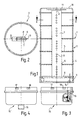
- the signal lamp 1 according to FIG. 1 comprises a spherical cap 2 and a base 3.
- the cap 2 is made of individual Segments 4 composed, the individual segments 4th firmly connected to each other, e.g. welded or glued are.
- the connection of the calotte 2 to the base 3 is also executed accordingly, so that one as a whole manageable unit results.
- Each segment 4 is provided with a crossbar 5, which at the composite calotte 2 as an intermediate floor or as Glare and reflection aid.
- a light-emitting diode printed circuit board 7 Through a central recess 6 of the crossbars or Intermediate shelves 5 is a light-emitting diode printed circuit board 7 introduced. It carries several light-emitting diodes 8 which are assigned in groups to a segment 4 and each accordingly between the two, the corresponding Segment 4 delimiting cross bars or intermediate floors are located.
- the LED circuit board 7 is strip-shaped and in inserted a transverse plug-in board 9, which in not shown the contacting the required electrical lines is made.
- the Bread board 9 carries the necessary control unit, which consists of For reasons of better clarity in Figure 1 not in Individual is shown.
- a End cover 10 At the top of the calotte 2 is a End cover 10, which is also fixed to the segments 4th connected, for example welded or glued. On the inside there is a piezo buzzer 11 in the end cover 10 hung swingable. Plug contacts 12 take care of the Connection of the piezo buzzer to the not in detail Control unit shown on the breadboard 9.
- the Recess 6 has two lateral guide slots 13, in which the LED circuit board 7 is guided.
- the Guide slots 13 are used for easy positioning and at the same time the stabilization of the circuit board 7.
- the width B the recess 6 is in accordance with the size of the LED 8 choose so that the LED circuit board 7 can be freely inserted is ensured by the crossbars 5.
- the contacting takes place via contact pins 14 to the outside.
- the base 3 can be designed to be open or closed, for example for sealing the interior of the signal tower 2.
- the contact pins 14 are used for contacting in an associated socket 15 or 15 '(cf. Figures 3 and 4) when fixing the base 3 and thus the entire signal tower 1 on the socket 15.
- the version 15 according to FIG. 3 is not a corresponding one Cable entry shown in detail provided to the Connect the signal lamp 7.
- a connector 16 is attached so that the electrical connection by plugging an appropriate Socket takes place.
- the version 15 'could also accordingly wear a socket that with a corresponding cable-side connector can be connected.
- the LEDs can now be on the LED circuit board be white, while the individual segments 4 with different colors. That way one and the same LED circuit board training for different domes 2 can be used.
- the LEDs 8 can be grouped after the assigned segment 4 a different color exhibit.
- the cost advantage of cheaper LEDs for At the current time there is the possibility a single-colored or transparent dome 2 with corresponding manufacturing advantages, especially if the calotte 2 in one piece with glare and reflection aids is trained.
- a completely colorless transparent dome 2 there is still the possibility with the help of different colored LEDs of the same LED group in each segment 4 individual segments 4 two or assign multiple colors depending on the application can be controlled. In principle, mixed colors are also through appropriate control of the LED is conceivable.
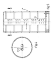
- FIGS. 5 and 6 corresponds to Essentially the aforementioned embodiment, wherein now so-called instead of individual LED 8 or LED chips SMD components are provided, which in turn light emitting diodes 20 with different radiation directions.
- the Signal tower 21 according to FIG. 5 is still without a piezo buzzer 11 executed, also in this embodiment at Such a piezo buzzer is required in accordance with the aforementioned Embodiment is to be attached.
- FIG. 7 shows a further embodiment of an LED circuit board 23, as shown in an inventive Signal tower can be used.
- the plug contacts 24 for contact with the breadboard 9 and in the upper area the contacts 25 for connecting one Piezo-Summers 11 shown.
- Different LEDs are in Groups 26, 27, 28 arranged. These LED groups 26, 27, 28 form 4 according to the invention together with the respective segment Signal elements of a signal tower 1. For example the LED of the LED group 26 yellow, the LED group 27 green and the LED group 28 be red.
- the embodiment can be in the form of LED chips on the LED Printed circuit board 23 are attached.
- FIG. 8 shows a corresponding one Printed circuit board 29, which now differs from the aforementioned Embodiment according to Figure 7 a widened Foot area 30 is provided on the further electronic Components, e.g. the control unit is to be accommodated.
- This Embodiment can be used for a signal tower which instead of the breadboard 9 and the contacting Contact pins 14 in a socket 15 directly on a cable is clamped, the corresponding contact elements, such as. a cable clamp on the extended if necessary Foot area 30 of the board finds space.
- Such Embodiment can in turn with a frame accordingly the version 15 are provided, the components for Contacting can be omitted. In this case, it will a cable entry inserted cable directly on the LED circuit board 29 connected.
- the connector 16 or a corresponding one Socket directly with appropriate cable clamps or other Connecting elements, e.g. Solder pins, etc. in the foot area 30 get connected.
Applications Claiming Priority (2)
| Application Number | Priority Date | Filing Date | Title |
|---|---|---|---|
| DE10212895 | 2002-03-22 | ||
| DE10212895A DE10212895A1 (de) | 2002-03-22 | 2002-03-22 | Signalsäule |
Publications (3)
| Publication Number | Publication Date |
|---|---|
| EP1347233A2 true EP1347233A2 (fr) | 2003-09-24 |
| EP1347233A3 EP1347233A3 (fr) | 2005-11-16 |
| EP1347233B1 EP1347233B1 (fr) | 2007-01-24 |
Family
ID=27771501
Family Applications (1)
| Application Number | Title | Priority Date | Filing Date |
|---|---|---|---|
| EP03006308A Expired - Lifetime EP1347233B1 (fr) | 2002-03-22 | 2003-03-20 | Colonne de signalisation |
Country Status (2)
| Country | Link |
|---|---|
| EP (1) | EP1347233B1 (fr) |
| DE (2) | DE10212895A1 (fr) |
Cited By (14)
| Publication number | Priority date | Publication date | Assignee | Title |
|---|---|---|---|---|
| EP1650489A2 (fr) * | 2004-10-22 | 2006-04-26 | WERMA Signaltechnik GmbH & Co.KG | Dispositif de signalisation, notamment colonne de signalisation |
| EP1650721A1 (fr) * | 2004-10-22 | 2006-04-26 | WERMA Signaltechnik GmbH & Co.KG | Dispositif de signalisation en particulier colonne de signalisation |
| WO2006066300A1 (fr) * | 2004-12-22 | 2006-06-29 | J. Auer - Fabrik Elektrischer Maschinen Gesellschaft M.B.H. | Colonne lumineuse d'avertissement |
| ITUD20090194A1 (it) * | 2009-11-10 | 2011-05-11 | Mizza Renato Di Balzarotti Ambrogio | Dispositivo di segnalazione luminosa |
| CN102466180A (zh) * | 2010-10-29 | 2012-05-23 | 迪吉多电子股份有限公司 | 指示灯 |
| DE202012100962U1 (de) * | 2012-03-19 | 2013-06-25 | Chiron-Werke Gmbh & Co. Kg | Maschinenleuchte |
| EP3031761A1 (fr) * | 2014-12-13 | 2016-06-15 | Saurer Germany GmbH & Co. KG | Machine textile multi-position |
| EP3043111A1 (fr) | 2015-01-12 | 2016-07-13 | AUER Signal GmbH | Dispositif de signalisation |
| DE202015009051U1 (de) | 2015-01-12 | 2016-08-03 | Auer Signal Gmbh | Signalvorrichtung |
| DE102015120280A1 (de) * | 2015-11-24 | 2017-05-24 | Werma Holding Gmbh + Co. Kg | Signalgerät mit Leuchtmodul |
| DE202015009420U1 (de) | 2015-01-12 | 2017-07-12 | Auer Signal Gmbh | Signalvorrichtung |
| EP2719803A3 (fr) * | 2008-09-17 | 2017-12-13 | Murata Machinery, Ltd. | Machine textile |
| WO2020161048A1 (fr) * | 2019-02-08 | 2020-08-13 | Picanol | Système de signalisation pour métier à tisser |
| DE102021133541A1 (de) | 2021-12-16 | 2023-06-22 | Reto Zimmermann | Signalpfosten |
Families Citing this family (5)
| Publication number | Priority date | Publication date | Assignee | Title |
|---|---|---|---|---|
| DE102010002389A1 (de) * | 2010-02-26 | 2011-09-01 | Osram Gesellschaft mit beschränkter Haftung | Grundträger, Lichtquellenträger und System aus Grundträger und Lichtquellenträger |
| DE102015001895A1 (de) * | 2015-02-18 | 2016-08-18 | Werma Holding Gmbh + Co. Kg | Signalgerät, insbesondere Signalsäule |
| DE102015104273A1 (de) * | 2015-03-23 | 2016-09-29 | Eaton Electrical Ip Gmbh & Co. Kg | Signalisierungsvorrichtung für Befehls- und/oder Meldegeräte |
| DE102017121186A1 (de) * | 2017-09-13 | 2019-03-14 | Eaton Intelligent Power Limited | Signalleuchte und Signalmodul |
| DE102021129995A1 (de) | 2021-11-17 | 2023-05-17 | 1St Systems Automation Gmbh | Anzeige |
Citations (1)
| Publication number | Priority date | Publication date | Assignee | Title |
|---|---|---|---|---|
| DE19513983A1 (de) | 1994-04-15 | 1995-10-19 | Werma Signalgeraete Gmbh & Co | Signalsäule |
Family Cites Families (6)
| Publication number | Priority date | Publication date | Assignee | Title |
|---|---|---|---|---|
| IT217140Z2 (it) * | 1989-07-11 | 1991-11-12 | Sirena Spa | Dispositivo segnalatore ottico par ticolarmente per impiego industria le |
| US5374876A (en) * | 1991-12-19 | 1994-12-20 | Hiroshi Horibata | Portable multi-color signal light with selectively switchable LED and incandescent illumination |
| KR0134353Y1 (ko) * | 1995-10-09 | 1999-01-15 | 이항복 | 교통신호봉 |
| US6626557B1 (en) * | 1999-12-29 | 2003-09-30 | Spx Corporation | Multi-colored industrial signal device |
| EP1146278A3 (fr) * | 2000-04-12 | 2004-01-21 | WERMA Signaltechnik GmbH & Co. | Dispositif d' éclairage, notamment pour lampe de signalisation |
| DE20204206U1 (de) * | 2002-03-15 | 2002-07-25 | Hesse Joachim | Mehrfarben-LED-Leuchtmittel für Signalleuchten |
-
2002
- 2002-03-22 DE DE10212895A patent/DE10212895A1/de not_active Withdrawn
-
2003
- 2003-03-20 EP EP03006308A patent/EP1347233B1/fr not_active Expired - Lifetime
- 2003-03-20 DE DE50306343T patent/DE50306343D1/de not_active Expired - Lifetime
Patent Citations (1)
| Publication number | Priority date | Publication date | Assignee | Title |
|---|---|---|---|---|
| DE19513983A1 (de) | 1994-04-15 | 1995-10-19 | Werma Signalgeraete Gmbh & Co | Signalsäule |
Cited By (25)
| Publication number | Priority date | Publication date | Assignee | Title |
|---|---|---|---|---|
| EP1650721A1 (fr) * | 2004-10-22 | 2006-04-26 | WERMA Signaltechnik GmbH & Co.KG | Dispositif de signalisation en particulier colonne de signalisation |
| EP1650489A3 (fr) * | 2004-10-22 | 2007-01-31 | WERMA Signaltechnik GmbH & Co.KG | Dispositif de signalisation, notamment colonne de signalisation |
| US7545284B2 (en) | 2004-10-22 | 2009-06-09 | Werma Signaltechnik Gmbh & Co. Kg | Signaling appliance, in particular a signaling column |
| EP1650489A2 (fr) * | 2004-10-22 | 2006-04-26 | WERMA Signaltechnik GmbH & Co.KG | Dispositif de signalisation, notamment colonne de signalisation |
| WO2006066300A1 (fr) * | 2004-12-22 | 2006-06-29 | J. Auer - Fabrik Elektrischer Maschinen Gesellschaft M.B.H. | Colonne lumineuse d'avertissement |
| EP2719803A3 (fr) * | 2008-09-17 | 2017-12-13 | Murata Machinery, Ltd. | Machine textile |
| ITUD20090194A1 (it) * | 2009-11-10 | 2011-05-11 | Mizza Renato Di Balzarotti Ambrogio | Dispositivo di segnalazione luminosa |
| EP2320126A1 (fr) | 2009-11-10 | 2011-05-11 | Mizza Renato Di Balzarotti Ambrogio | Dispositif de signalisation lumineuse |
| CN102466180A (zh) * | 2010-10-29 | 2012-05-23 | 迪吉多电子股份有限公司 | 指示灯 |
| CN102466180B (zh) * | 2010-10-29 | 2014-08-27 | 迪吉多电子股份有限公司 | 指示灯 |
| DE202012100962U1 (de) * | 2012-03-19 | 2013-06-25 | Chiron-Werke Gmbh & Co. Kg | Maschinenleuchte |
| US10337127B2 (en) | 2014-12-13 | 2019-07-02 | Saurer Spinning Solutions Gmbh & Co. Kg | Multipoint textile machine |
| EP3031761A1 (fr) * | 2014-12-13 | 2016-06-15 | Saurer Germany GmbH & Co. KG | Machine textile multi-position |
| US11198956B2 (en) | 2014-12-13 | 2021-12-14 | Saurer Spinning Solutions Gmbh & Co. Kg | Multipoint textile machine |
| EP3205933A1 (fr) | 2015-01-12 | 2017-08-16 | AUER Signal GmbH | Dispositif de signal |
| DE202015009051U1 (de) | 2015-01-12 | 2016-08-03 | Auer Signal Gmbh | Signalvorrichtung |
| EP3043111A1 (fr) | 2015-01-12 | 2016-07-13 | AUER Signal GmbH | Dispositif de signalisation |
| DE202015009420U1 (de) | 2015-01-12 | 2017-07-12 | Auer Signal Gmbh | Signalvorrichtung |
| US10134246B2 (en) | 2015-11-24 | 2018-11-20 | Werma Holding Gmbh + Co. .Kg | Signaling device with light module |
| DE102015120280A1 (de) * | 2015-11-24 | 2017-05-24 | Werma Holding Gmbh + Co. Kg | Signalgerät mit Leuchtmodul |
| WO2020161048A1 (fr) * | 2019-02-08 | 2020-08-13 | Picanol | Système de signalisation pour métier à tisser |
| BE1027040B1 (nl) * | 2019-02-08 | 2020-09-07 | Picanol Nv | Signaleringssysteem voor een weefmachine |
| CN113396253A (zh) * | 2019-02-08 | 2021-09-14 | 必佳乐公司 | 用于织机的信令系统 |
| CN113396253B (zh) * | 2019-02-08 | 2023-03-10 | 必佳乐公司 | 用于织机的信令系统 |
| DE102021133541A1 (de) | 2021-12-16 | 2023-06-22 | Reto Zimmermann | Signalpfosten |
Also Published As
| Publication number | Publication date |
|---|---|
| EP1347233A3 (fr) | 2005-11-16 |
| DE10212895A1 (de) | 2003-10-02 |
| EP1347233B1 (fr) | 2007-01-24 |
| DE50306343D1 (de) | 2007-03-15 |
Similar Documents
| Publication | Publication Date | Title |
|---|---|---|
| EP1347233B1 (fr) | Colonne de signalisation | |
| EP1405377B1 (fr) | Module a diodes electroluminescentes pour dispositifs d'eclairage | |
| DE102008005823A1 (de) | Anschlusselement zur elektrischen Anbindung einer LED | |
| DE102007026960A1 (de) | Flexibler Lichtbalken und dessen Herstellung | |
| DE102008034956A1 (de) | Verbindungselement zur Bildung bandförmiger Beleuchtungen und damit hergestelltes Beleuchtungselement | |
| DE102012203886A1 (de) | Leuchtdiodenlampe und Verfahren zum Fertigen einer Leuchtdiodenlampe | |
| DE102009014514A1 (de) | Beleuchtungseinrichtung | |
| DE202007005495U1 (de) | Warnleuchtsäule | |
| WO2014202666A1 (fr) | Luminaire destiné à être utilisé dans un système de rampe d'éclairage ainsi que système de rampe d'éclairage | |
| DE10260683A1 (de) | LED-Leuchtvorrichtung | |
| DE102009042615B4 (de) | Anschlusselement zur elektrischen Anbindung einer LED | |
| DE10111594A1 (de) | Anzeigeleuchtensäule | |
| EP1107389A1 (fr) | Dispositif d'éclairage pour un véhicule | |
| DE202012009416U1 (de) | Leuchtvorrichtung | |
| DE102013223412A1 (de) | Halterverbund und optoelektronische Anordnung | |
| DE102005032315A1 (de) | Lampe | |
| EP1146278A2 (fr) | Dispositif d' éclairage, notamment pour lampe de signalisation | |
| DE10326063B4 (de) | Beleuchtungseinrichtung | |
| DE4141980A1 (de) | Leuchtdiode mit einer umhuellung | |
| DE10038561A1 (de) | Leuchtmittel, insbesondere für eine Signalleuchte | |
| DE102005027530B4 (de) | Beleuchtungsmodul für die Hinterleuchtung und Ausleuchtung von hohlen Stellrädern, Markierungen oder zur Funktionsanzeige | |
| WO2012135878A1 (fr) | Dispositif de fixation et de mise en contact d'une lampe et/ou d'un module lumineux, ainsi que luminaire | |
| EP3165821A1 (fr) | Élément de bande lumineuse allongé | |
| DE20220650U1 (de) | Signalsäule | |
| DE102007056270A1 (de) | Beleuchtungseinheit mit einer LED-Lichtquelle |
Legal Events
| Date | Code | Title | Description |
|---|---|---|---|
| PUAI | Public reference made under article 153(3) epc to a published international application that has entered the european phase |
Free format text: ORIGINAL CODE: 0009012 |
|
| AK | Designated contracting states |
Kind code of ref document: A2 Designated state(s): AT BE BG CH CY CZ DE DK EE ES FI FR GB GR HU IE IT LI LU MC NL PT RO SE SI SK TR |
|
| AX | Request for extension of the european patent |
Extension state: AL LT LV MK |
|
| PUAL | Search report despatched |
Free format text: ORIGINAL CODE: 0009013 |
|
| AK | Designated contracting states |
Kind code of ref document: A3 Designated state(s): AT BE BG CH CY CZ DE DK EE ES FI FR GB GR HU IE IT LI LU MC NL PT RO SE SI SK TR |
|
| AX | Request for extension of the european patent |
Extension state: AL LT LV MK |
|
| 17P | Request for examination filed |
Effective date: 20060218 |
|
| AKX | Designation fees paid |
Designated state(s): DE FR GB IT |
|
| GRAP | Despatch of communication of intention to grant a patent |
Free format text: ORIGINAL CODE: EPIDOSNIGR1 |
|
| RIC1 | Information provided on ipc code assigned before grant |
Ipc: F21Y 101/02 20060101ALI20060831BHEP Ipc: F21W 111/00 20060101ALI20060831BHEP Ipc: F21S 8/00 20060101AFI20060831BHEP |
|
| GRAS | Grant fee paid |
Free format text: ORIGINAL CODE: EPIDOSNIGR3 |
|
| GRAA | (expected) grant |
Free format text: ORIGINAL CODE: 0009210 |
|
| AK | Designated contracting states |
Kind code of ref document: B1 Designated state(s): DE FR GB IT |
|
| REG | Reference to a national code |
Ref country code: GB Ref legal event code: FG4D Free format text: NOT ENGLISH |
|
| GBT | Gb: translation of ep patent filed (gb section 77(6)(a)/1977) |
Effective date: 20070214 |
|
| REF | Corresponds to: |
Ref document number: 50306343 Country of ref document: DE Date of ref document: 20070315 Kind code of ref document: P |
|
| ET | Fr: translation filed | ||
| PLBE | No opposition filed within time limit |
Free format text: ORIGINAL CODE: 0009261 |
|
| STAA | Information on the status of an ep patent application or granted ep patent |
Free format text: STATUS: NO OPPOSITION FILED WITHIN TIME LIMIT |
|
| 26N | No opposition filed |
Effective date: 20071025 |
|
| REG | Reference to a national code |
Ref country code: FR Ref legal event code: CD |
|
| REG | Reference to a national code |
Ref country code: FR Ref legal event code: PLFP Year of fee payment: 14 |
|
| REG | Reference to a national code |
Ref country code: FR Ref legal event code: PLFP Year of fee payment: 15 |
|
| REG | Reference to a national code |
Ref country code: FR Ref legal event code: PLFP Year of fee payment: 16 |
|
| PGFP | Annual fee paid to national office [announced via postgrant information from national office to epo] |
Ref country code: GB Payment date: 20220324 Year of fee payment: 20 Ref country code: DE Payment date: 20220322 Year of fee payment: 20 |
|
| PGFP | Annual fee paid to national office [announced via postgrant information from national office to epo] |
Ref country code: FR Payment date: 20220322 Year of fee payment: 20 |
|
| PGFP | Annual fee paid to national office [announced via postgrant information from national office to epo] |
Ref country code: IT Payment date: 20220331 Year of fee payment: 20 |
|
| REG | Reference to a national code |
Ref country code: DE Ref legal event code: R071 Ref document number: 50306343 Country of ref document: DE |
|
| REG | Reference to a national code |
Ref country code: GB Ref legal event code: PE20 Expiry date: 20230319 |
|
| PG25 | Lapsed in a contracting state [announced via postgrant information from national office to epo] |
Ref country code: GB Free format text: LAPSE BECAUSE OF EXPIRATION OF PROTECTION Effective date: 20230319 |