EP1346868A1 - Pédale d'accélérateur intelligent - Google Patents
Pédale d'accélérateur intelligent Download PDFInfo
- Publication number
- EP1346868A1 EP1346868A1 EP03004119A EP03004119A EP1346868A1 EP 1346868 A1 EP1346868 A1 EP 1346868A1 EP 03004119 A EP03004119 A EP 03004119A EP 03004119 A EP03004119 A EP 03004119A EP 1346868 A1 EP1346868 A1 EP 1346868A1
- Authority
- EP
- European Patent Office
- Prior art keywords
- unit
- pedal
- accelerator pedal
- motor
- sensor
- Prior art date
- Legal status (The legal status is an assumption and is not a legal conclusion. Google has not performed a legal analysis and makes no representation as to the accuracy of the status listed.)
- Granted
Links
Images


Classifications
-
- G—PHYSICS
- G05—CONTROLLING; REGULATING
- G05G—CONTROL DEVICES OR SYSTEMS INSOFAR AS CHARACTERISED BY MECHANICAL FEATURES ONLY
- G05G1/00—Controlling members, e.g. knobs or handles; Assemblies or arrangements thereof; Indicating position of controlling members
- G05G1/30—Controlling members actuated by foot
-
- B—PERFORMING OPERATIONS; TRANSPORTING
- B60—VEHICLES IN GENERAL
- B60K—ARRANGEMENT OR MOUNTING OF PROPULSION UNITS OR OF TRANSMISSIONS IN VEHICLES; ARRANGEMENT OR MOUNTING OF PLURAL DIVERSE PRIME-MOVERS IN VEHICLES; AUXILIARY DRIVES FOR VEHICLES; INSTRUMENTATION OR DASHBOARDS FOR VEHICLES; ARRANGEMENTS IN CONNECTION WITH COOLING, AIR INTAKE, GAS EXHAUST OR FUEL SUPPLY OF PROPULSION UNITS IN VEHICLES
- B60K26/00—Arrangements or mounting of propulsion unit control devices in vehicles
- B60K26/02—Arrangements or mounting of propulsion unit control devices in vehicles of initiating means or elements
- B60K26/021—Arrangements or mounting of propulsion unit control devices in vehicles of initiating means or elements with means for providing feel, e.g. by changing pedal force characteristics
-
- F—MECHANICAL ENGINEERING; LIGHTING; HEATING; WEAPONS; BLASTING
- F02—COMBUSTION ENGINES; HOT-GAS OR COMBUSTION-PRODUCT ENGINE PLANTS
- F02D—CONTROLLING COMBUSTION ENGINES
- F02D11/00—Arrangements for, or adaptations to, non-automatic engine control initiation means, e.g. operator initiated
- F02D11/02—Arrangements for, or adaptations to, non-automatic engine control initiation means, e.g. operator initiated characterised by hand, foot, or like operator controlled initiation means
-
- G—PHYSICS
- G05—CONTROLLING; REGULATING
- G05G—CONTROL DEVICES OR SYSTEMS INSOFAR AS CHARACTERISED BY MECHANICAL FEATURES ONLY
- G05G5/00—Means for preventing, limiting or returning the movements of parts of a control mechanism, e.g. locking controlling member
- G05G5/03—Means for enhancing the operator's awareness of arrival of the controlling member at a command or datum position; Providing feel, e.g. means for creating a counterforce
-
- Y—GENERAL TAGGING OF NEW TECHNOLOGICAL DEVELOPMENTS; GENERAL TAGGING OF CROSS-SECTIONAL TECHNOLOGIES SPANNING OVER SEVERAL SECTIONS OF THE IPC; TECHNICAL SUBJECTS COVERED BY FORMER USPC CROSS-REFERENCE ART COLLECTIONS [XRACs] AND DIGESTS
- Y10—TECHNICAL SUBJECTS COVERED BY FORMER USPC
- Y10T—TECHNICAL SUBJECTS COVERED BY FORMER US CLASSIFICATION
- Y10T74/00—Machine element or mechanism
- Y10T74/20—Control lever and linkage systems
- Y10T74/20528—Foot operated
- Y10T74/20534—Accelerator
-
- Y—GENERAL TAGGING OF NEW TECHNOLOGICAL DEVELOPMENTS; GENERAL TAGGING OF CROSS-SECTIONAL TECHNOLOGIES SPANNING OVER SEVERAL SECTIONS OF THE IPC; TECHNICAL SUBJECTS COVERED BY FORMER USPC CROSS-REFERENCE ART COLLECTIONS [XRACs] AND DIGESTS
- Y10—TECHNICAL SUBJECTS COVERED BY FORMER USPC
- Y10T—TECHNICAL SUBJECTS COVERED BY FORMER US CLASSIFICATION
- Y10T74/00—Machine element or mechanism
- Y10T74/20—Control lever and linkage systems
- Y10T74/20528—Foot operated
- Y10T74/2054—Signal
Definitions
- a device of the type mentioned is from DE 298 05 253 U1 known.
- a pedal element with a Piston rod of a piston of a hydraulic cylinder connected. Its cylinder element is with a hydraulic fluid filled. Above the highest and the lowest position the piston is a hydraulic line with the cylinder element connected.
- the decision logic is as programmable Computer unit executed. With the micro computer unit a distance sensor is connected. Dependent on from the distance determined by the sensor, the valve controlled and regulates the flow of hydraulic oil.
- the advantages achieved with the invention are in particular in that by the motor unit of the foot operating force the driver suddenly opposed a counterforce becomes. As a result, the driver is on a Dangerous situation alerted and can be done accordingly react. If the motor unit is switched off again, is the opposing force also suddenly no longer exists. hereby the driver is made aware that the dangerous situation has been cleared.
- the rotor unit of the motor unit can be operated with the pedal element and the stator unit of the motor unit with the base unit be connected via intermediate elements.
- the intermediate elements can be cables, gears or the like.
- the motor unit can be a torque motor that is in the accelerator pedal pivot point is arranged, its rotor unit with connected to the pedal element and its stator unit in the Base unit is arranged.
- the torque motor is as a motor can be used without intermediate gear.
- the control sensor element can act as a sensor for various dangers be trained. So the control sensor element Speed sensor, a distance sensor, a temperature sensor, or the like. It is also possible for everyone Connect sensor versions with the control unit. hereby the comfort of the intelligent accelerator pedal increases.
- the control unit can be a microcomputer unit with an E 2 PROM memory for entering the normal state.
- the E 2 PROM is a read-only memory that has the properties of a ROM in terms of overwritability. This makes it possible to enter the different normal states. With regard to reading out the written value for the normal state, the E 2 PROM behaves like a read-only memory, while the different normal states write like a RAM.
- the normal states are not limited to the three specified.
- the base unit can be a bottom plate of the accelerator pedal device his.
- the pedal element can consist of a pedal lever element and a Accelerator pedal element exist.
- the pedal lever element be connected to the bottom plate and at an accelerator pivot point move.
- the accelerator pedal element can be operated with the pedal lever element be connected and in an accelerator pedal pivot move. This makes it easy to use possible.
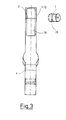
- a pedal lever element 5 is arranged movably.
- the pedal lever element is above an accelerator pedal pivot point 8 an accelerator pedal element 6 is movably connected.
- the end of Accelerator pedal element 6 is connected via a link coupling element 13 connected to the base element 4. This ensures that the accelerator pedal element 6 is always in the correct position with respect to the foot the driver is positioned. With the help of two Return elements 11, 12, the pedal lever element 5 and thus the accelerator pedal element 6 is always set to the starting position.
- Two damper elements 9, 10 ensure that the actuation of the pedal lever element damped by means of the accelerator pedal element 6 becomes.
- the two damper elements generate a damping force F9, 10, the actuation movement of the driver, 5 shows, counteracts.
- the damper elements 9, 10, the curve F9, 10 is easy arched.
- the two damper elements 9, 10 can be designed as brake cables that are carried over rough surfaces, which can have different roughnesses.
- a torque motor 1 is provided which is in the accelerator pedal pivot point 2 is arranged. This allows him to do his best Have an effect.
- the torque motor has the advantage that it can be used without a transmission gear.
- the torque motor is inside the base plate 11 is arranged. This will damage the Torque motor when the accelerator pedal is pressed by the foot of the driver avoided.
- the torque motor is shown in FIGS. 4a to 4b. He points as a rotor unit an annular, grooved torque motor rotor 16 with a large diameter. On the rotor 16 is a Pedal pin 15 arranged. With this pin the rotor connected to the pedal lever element 5.
- stator half 17.1, 17.2 classified To the left and right of the rotor 16 is a stator half 17.1, 17.2 classified. Moved with the help of a motor axis 18 the rotor 16 in the two stator halves.
- the torque motor 1 is shown in Fig. 4b.
- Fig. 4a is over the two stator halves to point 1, to point 2, at least partially a housing element 19 pushed.
- the housing element 19 is one Slot recess 20 introduced in which the pedal pin 15 can move freely.
- the speed range of the torque motor 1 is between 1 min -1 and approx. 1,200 min -1 and is suitable at high torques for a direct connection without an intermediate gear.
- the torque motor 1 is connected to a microcomputer unit 14 with an E 2 PROM.
- a control sensor element 21 is also arranged on the microcomputer unit 14.
- the control sensor element 21 can be used as a speed sensor, a distance sensor. Temperature sensor or the like may be formed.
- the vehicle driver Before the vehicle driver drives on the motorway, he has entered the prescribed speed of 130 km / h in the E 2 PROM. The vehicles traveling with him tempt him to exceed the prescribed maximum speed of 130 km / h as normal. The control sensor element detects this overshoot and passes it on to the microcomputer unit 14. The microcomputer unit 14 compares the actual value with the standard value and causes the torque motor 1 to be switched on immediately. The torque motor 1 develops a torque motor force F1 which, as shown in FIG. 5, has a linearly increasing effect.
Applications Claiming Priority (2)
| Application Number | Priority Date | Filing Date | Title |
|---|---|---|---|
| DE10211018 | 2002-03-13 | ||
| DE10211018A DE10211018A1 (de) | 2002-03-13 | 2002-03-13 | Intelligentes Fahrpedal |
Publications (2)
| Publication Number | Publication Date |
|---|---|
| EP1346868A1 true EP1346868A1 (fr) | 2003-09-24 |
| EP1346868B1 EP1346868B1 (fr) | 2006-06-21 |
Family
ID=27771239
Family Applications (1)
| Application Number | Title | Priority Date | Filing Date |
|---|---|---|---|
| EP03004119A Expired - Lifetime EP1346868B1 (fr) | 2002-03-13 | 2003-02-26 | Pédale d'accélérateur intelligent |
Country Status (4)
| Country | Link |
|---|---|
| US (1) | US6851333B2 (fr) |
| EP (1) | EP1346868B1 (fr) |
| AT (1) | ATE330808T1 (fr) |
| DE (2) | DE10211018A1 (fr) |
Cited By (1)
| Publication number | Priority date | Publication date | Assignee | Title |
|---|---|---|---|---|
| EP1602520A2 (fr) | 2004-06-05 | 2005-12-07 | AB Elektronik GmbH | Ensemble d'une pédale pour automobiles |
Families Citing this family (13)
| Publication number | Priority date | Publication date | Assignee | Title |
|---|---|---|---|---|
| US7044019B2 (en) | 2002-05-24 | 2006-05-16 | Ab Elektronik Gmbh | Accelerator pedal |
| DE102004002114B4 (de) * | 2004-01-14 | 2006-06-01 | Ab Elektronik Gmbh | Fahrpedaleinheit mit Kraftsprung-Element |
| DE102004024763B4 (de) * | 2004-05-17 | 2006-05-24 | Ab Elektronik Gmbh | Pedaleinheit |
| DE102004027499B4 (de) * | 2004-06-04 | 2006-02-23 | Ab Elektronik Gmbh | Pedaleinheit für ein Kraftfahrzeug |
| DE102005011025A1 (de) * | 2005-03-10 | 2006-09-14 | Volkswagen Ag | Verfahren zur Steuerung der Antriebsleistung einer Brennkraftmaschine |
| DE102007024885A1 (de) * | 2007-05-29 | 2008-12-04 | GM Global Technology Operations, Inc., Detroit | Informationssystem für ein Kraftfahrzeug |
| DE202008007799U1 (de) | 2008-06-11 | 2009-10-29 | Ab Elektronik Gmbh | Sicherheits-Steuersystem für Lkw |
| JP5206802B2 (ja) * | 2011-01-20 | 2013-06-12 | トヨタ自動車株式会社 | 車両の走行制御装置 |
| US8543303B2 (en) * | 2011-02-01 | 2013-09-24 | Rollfree Tek, Llc | Anti-rollback control system for hybrid and conventional powertrain vehicles |
| US20110172868A1 (en) * | 2011-02-01 | 2011-07-14 | Essam Tawfik Marcus | Anti-rollback Control System for Motor Vehicles |
| US20110166756A1 (en) * | 2011-02-01 | 2011-07-07 | Essam Tawfik Marcus | Anti-rollback Control System for Hybrid and Conventional Powertrain Vehicles |
| US8744671B2 (en) * | 2012-02-21 | 2014-06-03 | Chrysler Group Llc | System and method for detecting unintended stimulus at a vehicle pedal |
| DE102016119088A1 (de) * | 2016-10-07 | 2018-04-12 | Ab Elektronik Gmbh | Pedalvorrichtung mit Scharnierteil |
Citations (5)
| Publication number | Priority date | Publication date | Assignee | Title |
|---|---|---|---|---|
| JPH05231194A (ja) * | 1992-02-26 | 1993-09-07 | Nippondenso Co Ltd | アクセルペダルの踏込反力制御装置 |
| DE19506629A1 (de) * | 1995-02-25 | 1996-08-29 | Pierburg Gmbh | Fahrpedalanordnung für Fahrzeug-Brennkraftmaschinen |
| DE19620929A1 (de) * | 1996-05-24 | 1997-11-27 | Porsche Ag | Längsregelsystem für Kraftfahrzeuge mit haptischem Gaspedal |
| DE29805253U1 (de) * | 1998-03-24 | 1999-07-29 | A B Elektronik Gmbh | Vorrichtung zur Steuerung der Geschwindigkeit eines Fahrzeugs |
| WO2003039899A2 (fr) * | 2001-11-05 | 2003-05-15 | Continental Teves Ag & Co. Ohg | Dispositif a force de rappel supplementaire au niveau de l'accelerateur en fonction de l'ecart par rapport a une valeur theorique d'un parametre de vehicule |
Family Cites Families (3)
| Publication number | Priority date | Publication date | Assignee | Title |
|---|---|---|---|---|
| SE518099C2 (sv) * | 1997-11-21 | 2002-08-27 | Claes Johansson Automotive Ab | Inställbart pedalställ för ett fordon |
| US6330838B1 (en) * | 2000-05-11 | 2001-12-18 | Teleflex Incorporated | Pedal assembly with non-contact pedal position sensor for generating a control signal |
| DE10031097C1 (de) * | 2000-06-30 | 2002-02-21 | A B Elektronik Gmbh | Verfahren und Vorrichtungen zur Erzeugung von Kick-Down-Signalen |
-
2002
- 2002-03-13 DE DE10211018A patent/DE10211018A1/de not_active Withdrawn
-
2003
- 2003-01-21 US US10/348,619 patent/US6851333B2/en not_active Expired - Fee Related
- 2003-02-26 DE DE50303894T patent/DE50303894D1/de not_active Expired - Lifetime
- 2003-02-26 AT AT03004119T patent/ATE330808T1/de not_active IP Right Cessation
- 2003-02-26 EP EP03004119A patent/EP1346868B1/fr not_active Expired - Lifetime
Patent Citations (5)
| Publication number | Priority date | Publication date | Assignee | Title |
|---|---|---|---|---|
| JPH05231194A (ja) * | 1992-02-26 | 1993-09-07 | Nippondenso Co Ltd | アクセルペダルの踏込反力制御装置 |
| DE19506629A1 (de) * | 1995-02-25 | 1996-08-29 | Pierburg Gmbh | Fahrpedalanordnung für Fahrzeug-Brennkraftmaschinen |
| DE19620929A1 (de) * | 1996-05-24 | 1997-11-27 | Porsche Ag | Längsregelsystem für Kraftfahrzeuge mit haptischem Gaspedal |
| DE29805253U1 (de) * | 1998-03-24 | 1999-07-29 | A B Elektronik Gmbh | Vorrichtung zur Steuerung der Geschwindigkeit eines Fahrzeugs |
| WO2003039899A2 (fr) * | 2001-11-05 | 2003-05-15 | Continental Teves Ag & Co. Ohg | Dispositif a force de rappel supplementaire au niveau de l'accelerateur en fonction de l'ecart par rapport a une valeur theorique d'un parametre de vehicule |
Non-Patent Citations (1)
| Title |
|---|
| PATENT ABSTRACTS OF JAPAN vol. 017, no. 686 (M - 1529) 15 December 1993 (1993-12-15) * |
Cited By (4)
| Publication number | Priority date | Publication date | Assignee | Title |
|---|---|---|---|---|
| EP1602520A2 (fr) | 2004-06-05 | 2005-12-07 | AB Elektronik GmbH | Ensemble d'une pédale pour automobiles |
| DE102004027610A1 (de) * | 2004-06-05 | 2006-01-05 | Ab Elektronik Gmbh | Pedaleinheit und Pedalbaugruppe für Kraftfahrzeug |
| EP1602520A3 (fr) * | 2004-06-05 | 2006-08-16 | AB Elektronik GmbH | Ensemble d'une pédale pour automobiles |
| US7631574B2 (en) | 2004-06-05 | 2009-12-15 | AB Electronic GmbH | Accelerator pedal for a motor vehicle |
Also Published As
| Publication number | Publication date |
|---|---|
| ATE330808T1 (de) | 2006-07-15 |
| US20030172767A1 (en) | 2003-09-18 |
| DE10211018A1 (de) | 2003-10-09 |
| DE50303894D1 (de) | 2006-08-03 |
| EP1346868B1 (fr) | 2006-06-21 |
| US6851333B2 (en) | 2005-02-08 |
Similar Documents
| Publication | Publication Date | Title |
|---|---|---|
| EP1346868A1 (fr) | Pédale d'accélérateur intelligent | |
| DE3108247C2 (fr) | ||
| EP1165988B1 (fr) | Dispositif de changement de vitesses pour une boite de vitesses automatique | |
| DE102005062296B3 (de) | Getriebeschaltvorrichtung | |
| EP1268231B1 (fr) | Mode de manoeuvre pour vehicules a embrayage automatise | |
| EP1369763B9 (fr) | Pédale d'accélérateur | |
| WO2015055615A1 (fr) | Procédé permettant de guider un véhicule automobile et véhicule automobile permettant de mettre en œuvre le procédé | |
| DE2632313C3 (de) | Anlage zum Üben der Reaktion und des Fahrverhaltens eines Kraftfahrzeuglenkers in einer Notfallsituation | |
| EP0424629A1 (fr) | Dispositif d'arrêt dÀ©tachable pour la colonne de direction ajustable en longueur d'une voiture | |
| EP1106884A2 (fr) | Soupape de retenue avec dispositif d'étranglement et son procédé de production | |
| DE4446123C2 (de) | Vorrichtung zur Einwirkung auf die an der Lenkung eines Kraftfahrzeuges wirksamen Störkräfte | |
| DE19617566A1 (de) | Hydraulische Servolenkung eines Kraftfahrzeuges | |
| WO2000058646A1 (fr) | Dispositif de transmission pour vehicules | |
| DE2500903A1 (de) | Steuerungssystem fuer eine bremse | |
| DE10222984A1 (de) | Fahrpedal | |
| DE102008005829A1 (de) | Fahrzeugsitz mit einem höhenverstellbaren Sitzgestell | |
| WO1997000190A1 (fr) | Mecanisme electromecanique de direction a superposition pour un vehicule a chenilles | |
| EP3774462A1 (fr) | Système de freinage pour un véhicule doté d'une fonction de commande au moins partiellement automatisée | |
| DE10306136A1 (de) | Sicherheitsvorrichtung für ein Kraftfahrzeug | |
| DE3827724A1 (de) | Hilfskraftbetaetigte kupplungs- und gangschalteinrichtung | |
| DE3404378C1 (de) | Ventilsystem fuer eine hydraulisch gesteuerte Anfahr-Reibungskupplung,insbesondere fuer Kraftfahrzeuge | |
| EP0879335A1 (fr) | Ferme-porte et procede permettant de faire fonctionner un ferme-porte | |
| EP3267279A2 (fr) | Système de simulation de force exercée sur une pédale et véhicule automobile | |
| WO1989001880A1 (fr) | Systeme assiste d'embrayage et de changement de vitesse | |
| DE694872C (de) | Anfahr- und Bremssteuerung fuer elektrische Triebfahrzeuge |
Legal Events
| Date | Code | Title | Description |
|---|---|---|---|
| PUAI | Public reference made under article 153(3) epc to a published international application that has entered the european phase |
Free format text: ORIGINAL CODE: 0009012 |
|
| AK | Designated contracting states |
Kind code of ref document: A1 Designated state(s): AT BE BG CH CY CZ DE DK EE ES FI FR GB GR HU IE IT LI LU MC NL PT SE SI SK TR |
|
| AX | Request for extension of the european patent |
Extension state: AL LT LV MK RO |
|
| AKX | Designation fees paid | ||
| 17P | Request for examination filed |
Effective date: 20040512 |
|
| RBV | Designated contracting states (corrected) |
Designated state(s): AT BE BG CH CY CZ DE DK EE ES FI FR GB GR HU IE IT LI LU MC NL PT SE SI SK TR |
|
| REG | Reference to a national code |
Ref country code: DE Ref legal event code: 8566 |
|
| 17Q | First examination report despatched |
Effective date: 20040708 |
|
| GRAP | Despatch of communication of intention to grant a patent |
Free format text: ORIGINAL CODE: EPIDOSNIGR1 |
|
| GRAS | Grant fee paid |
Free format text: ORIGINAL CODE: EPIDOSNIGR3 |
|
| GRAA | (expected) grant |
Free format text: ORIGINAL CODE: 0009210 |
|
| AK | Designated contracting states |
Kind code of ref document: B1 Designated state(s): AT BE BG CH CY CZ DE DK EE ES FI FR GB GR HU IE IT LI LU MC NL PT SE SI SK TR |
|
| PG25 | Lapsed in a contracting state [announced via postgrant information from national office to epo] |
Ref country code: IT Free format text: LAPSE BECAUSE OF FAILURE TO SUBMIT A TRANSLATION OF THE DESCRIPTION OR TO PAY THE FEE WITHIN THE PRESCRIBED TIME-LIMIT;WARNING: LAPSES OF ITALIAN PATENTS WITH EFFECTIVE DATE BEFORE 2007 MAY HAVE OCCURRED AT ANY TIME BEFORE 2007. THE CORRECT EFFECTIVE DATE MAY BE DIFFERENT FROM THE ONE RECORDED. Effective date: 20060621 Ref country code: IE Free format text: LAPSE BECAUSE OF FAILURE TO SUBMIT A TRANSLATION OF THE DESCRIPTION OR TO PAY THE FEE WITHIN THE PRESCRIBED TIME-LIMIT Effective date: 20060621 Ref country code: NL Free format text: LAPSE BECAUSE OF FAILURE TO SUBMIT A TRANSLATION OF THE DESCRIPTION OR TO PAY THE FEE WITHIN THE PRESCRIBED TIME-LIMIT Effective date: 20060621 Ref country code: FI Free format text: LAPSE BECAUSE OF FAILURE TO SUBMIT A TRANSLATION OF THE DESCRIPTION OR TO PAY THE FEE WITHIN THE PRESCRIBED TIME-LIMIT Effective date: 20060621 Ref country code: SI Free format text: LAPSE BECAUSE OF FAILURE TO SUBMIT A TRANSLATION OF THE DESCRIPTION OR TO PAY THE FEE WITHIN THE PRESCRIBED TIME-LIMIT Effective date: 20060621 Ref country code: SK Free format text: LAPSE BECAUSE OF FAILURE TO SUBMIT A TRANSLATION OF THE DESCRIPTION OR TO PAY THE FEE WITHIN THE PRESCRIBED TIME-LIMIT Effective date: 20060621 Ref country code: CZ Free format text: LAPSE BECAUSE OF FAILURE TO SUBMIT A TRANSLATION OF THE DESCRIPTION OR TO PAY THE FEE WITHIN THE PRESCRIBED TIME-LIMIT Effective date: 20060621 |
|
| REG | Reference to a national code |
Ref country code: GB Ref legal event code: FG4D Free format text: NOT ENGLISH |
|
| REG | Reference to a national code |
Ref country code: CH Ref legal event code: EP |
|
| REG | Reference to a national code |
Ref country code: IE Ref legal event code: FG4D Free format text: LANGUAGE OF EP DOCUMENT: GERMAN |
|
| REF | Corresponds to: |
Ref document number: 50303894 Country of ref document: DE Date of ref document: 20060803 Kind code of ref document: P |
|
| PG25 | Lapsed in a contracting state [announced via postgrant information from national office to epo] |
Ref country code: DK Free format text: LAPSE BECAUSE OF FAILURE TO SUBMIT A TRANSLATION OF THE DESCRIPTION OR TO PAY THE FEE WITHIN THE PRESCRIBED TIME-LIMIT Effective date: 20060921 |
|
| PG25 | Lapsed in a contracting state [announced via postgrant information from national office to epo] |
Ref country code: ES Free format text: LAPSE BECAUSE OF FAILURE TO SUBMIT A TRANSLATION OF THE DESCRIPTION OR TO PAY THE FEE WITHIN THE PRESCRIBED TIME-LIMIT Effective date: 20061002 |
|
| REG | Reference to a national code |
Ref country code: SE Ref legal event code: TRGR |
|
| GBT | Gb: translation of ep patent filed (gb section 77(6)(a)/1977) |
Effective date: 20060923 |
|
| PG25 | Lapsed in a contracting state [announced via postgrant information from national office to epo] |
Ref country code: PT Free format text: LAPSE BECAUSE OF FAILURE TO SUBMIT A TRANSLATION OF THE DESCRIPTION OR TO PAY THE FEE WITHIN THE PRESCRIBED TIME-LIMIT Effective date: 20061121 |
|
| NLV1 | Nl: lapsed or annulled due to failure to fulfill the requirements of art. 29p and 29m of the patents act | ||
| ET | Fr: translation filed | ||
| REG | Reference to a national code |
Ref country code: IE Ref legal event code: FD4D |
|
| PG25 | Lapsed in a contracting state [announced via postgrant information from national office to epo] |
Ref country code: CH Free format text: LAPSE BECAUSE OF NON-PAYMENT OF DUE FEES Effective date: 20070228 Ref country code: MC Free format text: LAPSE BECAUSE OF NON-PAYMENT OF DUE FEES Effective date: 20070228 Ref country code: LI Free format text: LAPSE BECAUSE OF NON-PAYMENT OF DUE FEES Effective date: 20070228 |
|
| PLBE | No opposition filed within time limit |
Free format text: ORIGINAL CODE: 0009261 |
|
| STAA | Information on the status of an ep patent application or granted ep patent |
Free format text: STATUS: NO OPPOSITION FILED WITHIN TIME LIMIT |
|
| 26N | No opposition filed |
Effective date: 20070322 |
|
| REG | Reference to a national code |
Ref country code: CH Ref legal event code: PL |
|
| BERE | Be: lapsed |
Owner name: AB ELEKTRONIK G.M.B.H. Effective date: 20070228 |
|
| PG25 | Lapsed in a contracting state [announced via postgrant information from national office to epo] |
Ref country code: BE Free format text: LAPSE BECAUSE OF NON-PAYMENT OF DUE FEES Effective date: 20070228 |
|
| PG25 | Lapsed in a contracting state [announced via postgrant information from national office to epo] |
Ref country code: GR Free format text: LAPSE BECAUSE OF FAILURE TO SUBMIT A TRANSLATION OF THE DESCRIPTION OR TO PAY THE FEE WITHIN THE PRESCRIBED TIME-LIMIT Effective date: 20060922 |
|
| PG25 | Lapsed in a contracting state [announced via postgrant information from national office to epo] |
Ref country code: BG Free format text: LAPSE BECAUSE OF FAILURE TO SUBMIT A TRANSLATION OF THE DESCRIPTION OR TO PAY THE FEE WITHIN THE PRESCRIBED TIME-LIMIT Effective date: 20060921 Ref country code: AT Free format text: LAPSE BECAUSE OF NON-PAYMENT OF DUE FEES Effective date: 20070226 |
|
| PG25 | Lapsed in a contracting state [announced via postgrant information from national office to epo] |
Ref country code: EE Free format text: LAPSE BECAUSE OF FAILURE TO SUBMIT A TRANSLATION OF THE DESCRIPTION OR TO PAY THE FEE WITHIN THE PRESCRIBED TIME-LIMIT Effective date: 20060621 |
|
| PG25 | Lapsed in a contracting state [announced via postgrant information from national office to epo] |
Ref country code: CY Free format text: LAPSE BECAUSE OF FAILURE TO SUBMIT A TRANSLATION OF THE DESCRIPTION OR TO PAY THE FEE WITHIN THE PRESCRIBED TIME-LIMIT Effective date: 20060621 Ref country code: LU Free format text: LAPSE BECAUSE OF NON-PAYMENT OF DUE FEES Effective date: 20070226 |
|
| PG25 | Lapsed in a contracting state [announced via postgrant information from national office to epo] |
Ref country code: TR Free format text: LAPSE BECAUSE OF FAILURE TO SUBMIT A TRANSLATION OF THE DESCRIPTION OR TO PAY THE FEE WITHIN THE PRESCRIBED TIME-LIMIT Effective date: 20060621 Ref country code: HU Free format text: LAPSE BECAUSE OF FAILURE TO SUBMIT A TRANSLATION OF THE DESCRIPTION OR TO PAY THE FEE WITHIN THE PRESCRIBED TIME-LIMIT Effective date: 20061222 |
|
| PG25 | Lapsed in a contracting state [announced via postgrant information from national office to epo] |
Ref country code: IT Free format text: LAPSE BECAUSE OF NON-PAYMENT OF DUE FEES Effective date: 20090226 |
|
| PGRI | Patent reinstated in contracting state [announced from national office to epo] |
Ref country code: IT Effective date: 20110616 |
|
| PGFP | Annual fee paid to national office [announced via postgrant information from national office to epo] |
Ref country code: SE Payment date: 20140218 Year of fee payment: 12 |
|
| PGFP | Annual fee paid to national office [announced via postgrant information from national office to epo] |
Ref country code: FR Payment date: 20140219 Year of fee payment: 12 Ref country code: IT Payment date: 20140224 Year of fee payment: 12 |
|
| PGFP | Annual fee paid to national office [announced via postgrant information from national office to epo] |
Ref country code: GB Payment date: 20140218 Year of fee payment: 12 |
|
| REG | Reference to a national code |
Ref country code: DE Ref legal event code: R082 Ref document number: 50303894 Country of ref document: DE Representative=s name: BISCHOF & PARTNER RECHTSANWAELTE PARTNERSCHAFT, DE |
|
| PGFP | Annual fee paid to national office [announced via postgrant information from national office to epo] |
Ref country code: DE Payment date: 20150227 Year of fee payment: 13 |
|
| REG | Reference to a national code |
Ref country code: SE Ref legal event code: EUG |
|
| GBPC | Gb: european patent ceased through non-payment of renewal fee |
Effective date: 20150226 |
|
| REG | Reference to a national code |
Ref country code: FR Ref legal event code: ST Effective date: 20151030 |
|
| PG25 | Lapsed in a contracting state [announced via postgrant information from national office to epo] |
Ref country code: SE Free format text: LAPSE BECAUSE OF NON-PAYMENT OF DUE FEES Effective date: 20150227 |
|
| PG25 | Lapsed in a contracting state [announced via postgrant information from national office to epo] |
Ref country code: IT Free format text: LAPSE BECAUSE OF NON-PAYMENT OF DUE FEES Effective date: 20150226 |
|
| PG25 | Lapsed in a contracting state [announced via postgrant information from national office to epo] |
Ref country code: GB Free format text: LAPSE BECAUSE OF NON-PAYMENT OF DUE FEES Effective date: 20150226 |
|
| PG25 | Lapsed in a contracting state [announced via postgrant information from national office to epo] |
Ref country code: FR Free format text: LAPSE BECAUSE OF NON-PAYMENT OF DUE FEES Effective date: 20150302 |
|
| REG | Reference to a national code |
Ref country code: DE Ref legal event code: R119 Ref document number: 50303894 Country of ref document: DE |
|
| PG25 | Lapsed in a contracting state [announced via postgrant information from national office to epo] |
Ref country code: DE Free format text: LAPSE BECAUSE OF NON-PAYMENT OF DUE FEES Effective date: 20160901 |