EP1346741A2 - Abdeckbare Nadelvorrichtung mit angedrücktem Sicherheitsschutz - Google Patents
Abdeckbare Nadelvorrichtung mit angedrücktem Sicherheitsschutz Download PDFInfo
- Publication number
- EP1346741A2 EP1346741A2 EP03075800A EP03075800A EP1346741A2 EP 1346741 A2 EP1346741 A2 EP 1346741A2 EP 03075800 A EP03075800 A EP 03075800A EP 03075800 A EP03075800 A EP 03075800A EP 1346741 A2 EP1346741 A2 EP 1346741A2
- Authority
- EP
- European Patent Office
- Prior art keywords
- needle
- shield
- laterally extending
- distal end
- needle cannula
- Prior art date
- Legal status (The legal status is an assumption and is not a legal conclusion. Google has not performed a legal analysis and makes no representation as to the accuracy of the status listed.)
- Granted
Links
Images


Classifications
-
- A—HUMAN NECESSITIES
- A61—MEDICAL OR VETERINARY SCIENCE; HYGIENE
- A61M—DEVICES FOR INTRODUCING MEDIA INTO, OR ONTO, THE BODY; DEVICES FOR TRANSDUCING BODY MEDIA OR FOR TAKING MEDIA FROM THE BODY; DEVICES FOR PRODUCING OR ENDING SLEEP OR STUPOR
- A61M5/00—Devices for bringing media into the body in a subcutaneous, intra-vascular or intramuscular way; Accessories therefor, e.g. filling or cleaning devices, arm-rests
- A61M5/178—Syringes
- A61M5/31—Details
- A61M5/32—Needles; Details of needles pertaining to their connection with syringe or hub; Accessories for bringing the needle into, or holding the needle on, the body; Devices for protection of needles
- A61M5/3205—Apparatus for removing or disposing of used needles or syringes, e.g. containers; Means for protection against accidental injuries from used needles
- A61M5/321—Means for protection against accidental injuries by used needles
- A61M5/3216—Caps placed transversally onto the needle, e.g. pivotally attached to the needle base
-
- A—HUMAN NECESSITIES
- A61—MEDICAL OR VETERINARY SCIENCE; HYGIENE
- A61B—DIAGNOSIS; SURGERY; IDENTIFICATION
- A61B5/00—Measuring for diagnostic purposes; Identification of persons
- A61B5/15—Devices for taking samples of blood
- A61B5/150007—Details
- A61B5/150015—Source of blood
- A61B5/15003—Source of blood for venous or arterial blood
-
- A—HUMAN NECESSITIES
- A61—MEDICAL OR VETERINARY SCIENCE; HYGIENE
- A61B—DIAGNOSIS; SURGERY; IDENTIFICATION
- A61B5/00—Measuring for diagnostic purposes; Identification of persons
- A61B5/15—Devices for taking samples of blood
- A61B5/150007—Details
- A61B5/150206—Construction or design features not otherwise provided for; manufacturing or production; packages; sterilisation of piercing element, piercing device or sampling device
- A61B5/150259—Improved gripping, e.g. with high friction pattern or projections on the housing surface or an ergonometric shape
-
- A—HUMAN NECESSITIES
- A61—MEDICAL OR VETERINARY SCIENCE; HYGIENE
- A61B—DIAGNOSIS; SURGERY; IDENTIFICATION
- A61B5/00—Measuring for diagnostic purposes; Identification of persons
- A61B5/15—Devices for taking samples of blood
- A61B5/150007—Details
- A61B5/150374—Details of piercing elements or protective means for preventing accidental injuries by such piercing elements
- A61B5/150381—Design of piercing elements
- A61B5/150389—Hollow piercing elements, e.g. canulas, needles, for piercing the skin
-
- A—HUMAN NECESSITIES
- A61—MEDICAL OR VETERINARY SCIENCE; HYGIENE
- A61B—DIAGNOSIS; SURGERY; IDENTIFICATION
- A61B5/00—Measuring for diagnostic purposes; Identification of persons
- A61B5/15—Devices for taking samples of blood
- A61B5/150007—Details
- A61B5/150374—Details of piercing elements or protective means for preventing accidental injuries by such piercing elements
- A61B5/150381—Design of piercing elements
- A61B5/150473—Double-ended needles, e.g. used with pre-evacuated sampling tubes
-
- A—HUMAN NECESSITIES
- A61—MEDICAL OR VETERINARY SCIENCE; HYGIENE
- A61B—DIAGNOSIS; SURGERY; IDENTIFICATION
- A61B5/00—Measuring for diagnostic purposes; Identification of persons
- A61B5/15—Devices for taking samples of blood
- A61B5/150007—Details
- A61B5/150374—Details of piercing elements or protective means for preventing accidental injuries by such piercing elements
- A61B5/150381—Design of piercing elements
- A61B5/150503—Single-ended needles
-
- A—HUMAN NECESSITIES
- A61—MEDICAL OR VETERINARY SCIENCE; HYGIENE
- A61B—DIAGNOSIS; SURGERY; IDENTIFICATION
- A61B5/00—Measuring for diagnostic purposes; Identification of persons
- A61B5/15—Devices for taking samples of blood
- A61B5/150007—Details
- A61B5/150374—Details of piercing elements or protective means for preventing accidental injuries by such piercing elements
- A61B5/150534—Design of protective means for piercing elements for preventing accidental needle sticks, e.g. shields, caps, protectors, axially extensible sleeves, pivotable protective sleeves
- A61B5/150572—Pierceable protectors, e.g. shields, caps, sleeves or films, e.g. for hygienic purposes
-
- A—HUMAN NECESSITIES
- A61—MEDICAL OR VETERINARY SCIENCE; HYGIENE
- A61B—DIAGNOSIS; SURGERY; IDENTIFICATION
- A61B5/00—Measuring for diagnostic purposes; Identification of persons
- A61B5/15—Devices for taking samples of blood
- A61B5/150007—Details
- A61B5/150374—Details of piercing elements or protective means for preventing accidental injuries by such piercing elements
- A61B5/150534—Design of protective means for piercing elements for preventing accidental needle sticks, e.g. shields, caps, protectors, axially extensible sleeves, pivotable protective sleeves
- A61B5/150664—Pivotable protective sleeves, i.e. sleeves connected to, or integrated in, the piercing or driving device, and which are pivoted for covering or uncovering the piercing element
- A61B5/150671—Pivotable protective sleeves, i.e. sleeves connected to, or integrated in, the piercing or driving device, and which are pivoted for covering or uncovering the piercing element comprising means to impede repositioning of protection sleeve from covering to uncovering position
- A61B5/150687—Pivotable protective sleeves, i.e. sleeves connected to, or integrated in, the piercing or driving device, and which are pivoted for covering or uncovering the piercing element comprising means to impede repositioning of protection sleeve from covering to uncovering position semi-automatically triggered, i.e. in which the triggering of the pivotable protective sleeve requires a deliberate action by the user such as manual release of spring-biased extension means
-
- A—HUMAN NECESSITIES
- A61—MEDICAL OR VETERINARY SCIENCE; HYGIENE
- A61B—DIAGNOSIS; SURGERY; IDENTIFICATION
- A61B5/00—Measuring for diagnostic purposes; Identification of persons
- A61B5/15—Devices for taking samples of blood
- A61B5/150007—Details
- A61B5/150374—Details of piercing elements or protective means for preventing accidental injuries by such piercing elements
- A61B5/150534—Design of protective means for piercing elements for preventing accidental needle sticks, e.g. shields, caps, protectors, axially extensible sleeves, pivotable protective sleeves
- A61B5/150694—Procedure for removing protection means at the time of piercing
- A61B5/150717—Procedure for removing protection means at the time of piercing manually removed
-
- A—HUMAN NECESSITIES
- A61—MEDICAL OR VETERINARY SCIENCE; HYGIENE
- A61B—DIAGNOSIS; SURGERY; IDENTIFICATION
- A61B5/00—Measuring for diagnostic purposes; Identification of persons
- A61B5/15—Devices for taking samples of blood
- A61B5/150007—Details
- A61B5/150732—Needle holders, for instance for holding the needle by the hub, used for example with double-ended needle and pre-evacuated tube
-
- A—HUMAN NECESSITIES
- A61—MEDICAL OR VETERINARY SCIENCE; HYGIENE
- A61B—DIAGNOSIS; SURGERY; IDENTIFICATION
- A61B5/00—Measuring for diagnostic purposes; Identification of persons
- A61B5/15—Devices for taking samples of blood
- A61B5/153—Devices specially adapted for taking samples of venous or arterial blood, e.g. with syringes
- A61B5/154—Devices using pre-evacuated means
-
- A—HUMAN NECESSITIES
- A61—MEDICAL OR VETERINARY SCIENCE; HYGIENE
- A61M—DEVICES FOR INTRODUCING MEDIA INTO, OR ONTO, THE BODY; DEVICES FOR TRANSDUCING BODY MEDIA OR FOR TAKING MEDIA FROM THE BODY; DEVICES FOR PRODUCING OR ENDING SLEEP OR STUPOR
- A61M5/00—Devices for bringing media into the body in a subcutaneous, intra-vascular or intramuscular way; Accessories therefor, e.g. filling or cleaning devices, arm-rests
- A61M5/178—Syringes
- A61M5/31—Details
- A61M5/32—Needles; Details of needles pertaining to their connection with syringe or hub; Accessories for bringing the needle into, or holding the needle on, the body; Devices for protection of needles
- A61M5/3205—Apparatus for removing or disposing of used needles or syringes, e.g. containers; Means for protection against accidental injuries from used needles
- A61M5/321—Means for protection against accidental injuries by used needles
- A61M5/3216—Caps placed transversally onto the needle, e.g. pivotally attached to the needle base
- A61M5/3219—Semi-automatic repositioning of the cap, i.e. in which the repositioning of the cap to the needle covering position requires a deliberate action by the user to trigger the repositioning of the cap, e.g. manual release of spring-biased cap repositioning means
Definitions
- the present invention relates to a shield for a needle and more particularly to a safety shield assembly that may be used in conjunction with a syringe assembly, a hypodermic needle, a needle assembly, a needle assembly with a needle holder, a blood collection needle, a blood collection set, an intravenous infusion set or other fluid handling devices or assemblies that contain piercing elements.
- Disposable medical devices having piercing elements for administering a medication or withdrawing a fluid require safe and convenient handling.
- the piercing elements include, for example, pointed needle cannulae or blunt ended cannulae.
- Safe and convenient handling of disposable medical devices is recognized by those in the medical arts so as to minimize exposure to blood borne pathogens. Safe and convenient handling of disposable medical devices results in the disposal of the medical devices intact.
- a number of devices incorporate a pivoting shield assembly in which the shield can be pivoted away from the needle during use and pivoted about the needle after use, for protection from the used needle.
- U.S. Patent No. 5,603,699 discloses a needle guard assembly which includes a top shield member and a bottom lever member which pivot away from the needle of a syringe in opposing directions. The assembly further includes a series of gears between the top shield member and the bottom lever member, as well as a torsional coil spring mounted therebetween. Such an arrangement is not practically useful due to the complex arrangement of gears and opposing pivoting members.
- 5,401,251 discloses a syringe injection system including a hollow needle and a safety cap cover for covering the needle after use.
- the safety cap cover is attached to the body of the syringe through an elongated extension arm, which pivots the safety cap cover over the needle after use.
- the extension arm may be attached to the body of the syringe through a spring, which urges the arm and cover into the shielded position.
- the present invention is directed to a shieldable needle assembly, and in particular, to a needle safety device.
- the needle safety device includes a medical device, such as a blood collection needle holder or a syringe, including a forward or distal end having an opening therethrough and a laterally extending arm.
- a needle cannula extends from the forward or distal end of the medical device, with the needle cannula including a distal end having a puncture tip.
- a shield is pivotably connected to the forward or distal end of the medical device.
- the shield is pivotal with respect to the needle cannula between a shielded position encompassing the distal end of the needle cannula and a retracted or non-shielded position pivotally spaced from the distal end of the needle cannula.
- the shield includes a laterally extending lever which is adjacent the forward end of the medical device which includes the laterally extending arm.
- the laterally extending lever and the laterally extending arm are in close proximity and extend away from the same side of the assembly, represented by a plane defined by the longitudinal axis of the needle cannula and a pivot of the shield.
- a biasing element extends between the medical device and the shield, for biasing the shield toward the shielded position.
- the biasing element is capable of storing energy when the shield is in the non-shielded position for biasing the shield to the shielded position.
- the biasing element may be, for example, a wound coil torsion spring or a leaf spring, including first and second legs at opposite ends thereof. The first leg is in engagement with the laterally extending arm of the medical device and the second leg is in engagement with the laterally extending lever of the shield. The first and second legs may form the laterally extending arm and the laterally extending shield, respectively.
- the medical device and the shield may be integrally formed, desirably with the biasing element integral therebetween forming a leaf spring.
- the laterally extending lever of the shield and the laterally extending arm of the medical device may include interengaging structure for releasably holding the shield in the non-shielded position.
- the shield may include a needle cannula lock which is movable between a first position and a second position. In the first position, the needle cannula lock is bent, and provides for movement of the shield from the shielded position, such as when the needle device is in a packaged or pre-use state with the shield covering the needle cannula in a reversible shielded position.
- the needle cannula lock prevents movement of the shield from the shielded position, such as when the shield has been pivotably rotated to the non-shielded position and returned to the shielded position.
- a needle cannula lock may include a finger with a needle engaging barb on one side thereof, with the needle engaging barb engaging the needle cannula for preventing pivotal movement of the shield from the shielded position when the needle cannula lock is in the second position, and with the needle cannula releasably engaging an opposite side of the finger thereby allowing for movement of the shield from the shielded position when the needle cannula lock is in the first position.
- the needle cannula lock in the first position exerts a biasing force against the needle cannula, biasing the shield toward the non-shielded position, and the biasing element exerts a biasing force greater than the biasing force exerted by the cannula lock for maintaining the shield biased toward the shielded position.
- the invention is directed to a safety blood collection device including a needle holder as the medical device and having a laterally extending arm, with a needle cannula extending through an opening at the end of the needle holder.
- the needle cannula includes a non-patient end including a non-patient puncture tip extending within the needle holder, as well as an intravenous end including an intravenous puncture tip extending from the end of the needle holder.
- a sleeve may extend about the non-patient puncture tip.
- a shield is pivotably connected to the distal end of the needle holder, and is pivotal with respect to the needle cannula between a shielded position encompassing the distal end of the needle cannula and a non-shielded position pivotally spaced from the distal end of the needle cannula in a similar manner as set forth above, including a laterally extending lever and a biasing element for pivotal movement of the shield.
- the invention is directed to a safety needle assembly for use in conjunction with a medical device such as a needle holder or a syringe.
- a safety needle assembly includes a base hub having an internal opening therethrough, and a laterally extending arm extending from the outer wall of the base hub.
- a needle cannula extends from a forward or distal end of the base hub, with the needle including a puncture tip and an internal lumen in communication with the internal opening of the base hub.
- a shield is pivotably connected to the base hub, and is pivotal with respect to the needle cannula in a similar manner as described above, including a laterally extending lever and a biasing element for pivotal movement of the shield.
- the base hub preferably includes structure for mating with a medical device, such as a blood collection needle holder or a syringe.
- the needle cannula of such a safety needle assembly includes a non-patient end having a non-patient puncture tip extending from one end of the base hub, and an intravenous end including an intravenous puncture tip extending from the other end of the base hub.
- a sleeve may extend about the non-patient puncture tip.
- the invention in a further embodiment, relates to a safety needle assembly which includes a base hub including a proximal end and a distal end with a needle having a puncture tip extending from the distal end of the hub, a laterally extending arm adjacent the distal end of the hub and extending laterally from the hub, and a laterally extending lever extending laterally from the distal end of the hub.
- a hinge section is formed at the intersection of the laterally extending arm and the laterally extending lever defining an acute angle therebetween.
- the hinge section further defines a pivot axis for pivotal movement of the laterally extending lever with respect to the laterally extending arm between a first position and a second position with the second position defining an angle which is more acute than the first position.
- the assembly further includes a shield which is integral with the laterally extending lever and which extends toward the distal end of the needle for encompassing the distal end of the needle when the hinge is in the first position.
- a shield which is integral with the laterally extending lever and which extends toward the distal end of the needle for encompassing the distal end of the needle when the hinge is in the first position.
- the biasing energy accumulates in a spring element, causing a bending moment between the laterally extending arm and the laterally extending lever. More desirably, the biasing energy accumulates in the hinge section, with the hinge section forming a leaf spring.
- FIG. 1 is a perspective view of a needle assembly attached to a needle holder in accordance with one embodiment of the present invention, with the shield in a first packaging position prior to use;
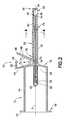
- FIG. 2 is a cross section of the needle assembly of FIG. 1;
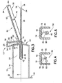
- FIG. 3 is a cross section of the needle assembly of FIG. 1 shown in a second position with the shield pivoted away from the needle for use;
- FIG. 4 is a transverse cross section taken along lines 4-4 of FIG. 2, showing the cannula lock in a first packaging position prior to use;
- FIG. 5 is a transverse cross section of the cannula lock in locked position when the needle assembly is in a shielded position;
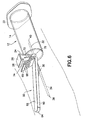
- FIG. 6 is a perspective view of the needle assembly of FIG. 1 shown in use in a blood collection procedure
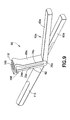
- FIG. 7 is a perspective view of a needle assembly attached to a needle holder in accordance with a further embodiment of the present invention.
- FIG. 8 is a perspective view of a needle assembly as in FIG. 1 shown with a needle cover covering the needle in an alternate packaging embodiment prior to use;
- FIG. 9 is a perspective view of a double ended needle assembly for attachment to a needle holder in accordance with a further embodiment of the invention.
- FIG. 10 is a cross section of the needle assembly of FIG. 9 shown in a sampling position
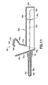
- FIG. 11 is a cross section of the needle assembly of FIG. 9 shown in a shielded position after use.
- FIG. 12 is a cross section of a needle assembly for attachment to a syringe in accordance with a further embodiment of the present invention.
- FIGS. 1-3 illustrate a needle safety device in accordance with the present invention and the related features, in the form of a blood collection device 10 .
- the present invention is generally described in terms of a needle safety device in the form of such a blood collection device, and encompasses such a device as well as a shieldable safety needle assembly for use in such a device.
- the safety needle device includes a medical device, such as a needle holder 12 for use in blood collection procedures, as shown in FIGS. 1-3. While described herein in terms of a blood collection device including a needle holder, the needle safety device of the present invention may incorporate other medical devices used in connection with a needle, such as a syringe assembly, a hypodermic needle, a needle assembly, a blood collection set, an intravenous infusion set or other fluid handing devices or medical device assemblies that contain piercing elements.
- a syringe assembly such as a hypodermic needle, a needle assembly, a blood collection set, an intravenous infusion set or other fluid handing devices or medical device assemblies that contain piercing elements.
- Needle holder 12 includes a generally tubular body 14 having proximal end 16 and distal end 18 at opposing ends thereof, with internal opening 20 extending therebetween.
- Proximal end 16 includes a flange 22 , which may extend circumferentially about proximal end 16 .
- Distal end 18 includes a distal opening 19 extending through tubular body 14 into internal opening 20 .
- Needle holder 12 further includes a laterally extending arm 24 which extends laterally away from tubular body 14 adjacent distal end 18. Laterally extending arm 24 extends laterally from axis X defining blood collection device 10 , and may be a generally planar structure. Laterally extending arm 24 is desirably integrally formed with needle holder 12 .
- Blood collection device 10 further includes needle cannula 30 extending from distal end 18 of needle holder 12 .
- the needle cannula 30 has a proximal end 32 and an opposing distal end 34 .
- the needle cannula 30 defines an internal lumen 36 extending through the needle cannula 30 from proximal end 32 to distal end 34 .
- Distal end 34 of needle cannula 30 is beveled to define a sharp puncture tip at intravenous puncture tip 38 .
- Intravenous puncture tip 38 is provided for insertion into a patient's blood vessel, such as a vein, and is, therefore, designed to provide ease of insertion and minimal discomfort during venipuncture. As FIGS.
- Non-patient puncture tip 40 is provided for puncturing of an evacuated tube, for example, during a blood collection procedure, and therefore includes a sharp puncture tip.
- Internal lumen 36 extends between intravenous puncture tip 38 and non-patient puncture tip 40 .
- An elastomeric sleeve 42 covers the non-patient puncture tip 40 at the proximal end 32 .
- a medical device in the form of a needle holder for blood collection
- other medical devices for use with a needle may be provided through the present invention, including a syringe.
- Blood collection device 10 further includes a shield 50 pivotably connected to needle holder 12 at distal end 18 .
- Shield 50 comprises a rearward end 52 and a forward end 54 .
- Forward end 54 of shield 50 includes a slot or longitudinal opening 56 formed by sidewalls 58 and 60 that extend downwardly from top section 62 and run substantially opposite of one another in parallel along the length of slot 56 towards forward endwall 64 .
- Shield 50 further includes a laterally extending lever 66 which extends laterally away from top section 62 of shield 50 at rearward end 52 , adjacent distal end 18 of needle holder 12 .
- Laterally extending lever 66 extends laterally away from axis X defining the blood collection device 10 , and may be a generally planar structure integrally formed with shield 50 .
- Bumps or ribs 68 may be provided on a surface of laterally extending lever 66 for providing a tactile surface for engagement with a user's finger.
- Shield 50 is pivotal with respect to needle cannula 30 about a pivoting point P between a retracted or non-shielded position as shown in FIG. 3 in which shield 50 is pivotally spaced from distal end 34 of needle cannula 30 , and a shielded position as shown in FIG. 2 in which the distal end 34 of needle cannula 30 is encompassed within slot 56 of shield 50 .
- Blood collection device 10 further includes a biasing element, such as spring 70 , extending between laterally extending arm 24 of needle holder 12 and laterally extending lever 66 of shield 50 .
- Spring 70 provides a biasing force between needle holder 12 and shield 50 , and includes stored energy for biasing shield 50 toward the shielded position encompassing needle cannula 30 .
- Spring 70 may be a wound torsion spring such as a coil spring shown in FIGS. 1-3, a compression spring, or a leaf spring.
- Spring 70 includes a first leg 72 and a second leg 74 at opposing ends.
- First leg 72 is in engagement with laterally extending arm 24 of needle holder 12
- second leg 74 is in engagement with laterally extending lever 66 of shield 50 .
- first leg 72 and second leg 74 of spring 70 may comprise laterally extending arm 24 and laterally extending lever 66 , such as depicted in FIG. 7, with first leg 72 and second leg 74 of the leaf spring forming laterally extending arm 24 and laterally extending lever 66 , respectively.
- laterally extending arm 24 and laterally extending lever 66 intersect to form a hinge section at spring 70 , with shield 50 integral with the laterally extending lever 66 and extending toward the distal end of needle cannula 30 .
- the leaf spring acts as a biased hinge between laterally extending arm 24 and laterally extending lever 66 .
- needle holder 12 , shield 50 and spring 70 are preferably unitarily formed as an integral part.
- Laterally extending arm 24 and laterally extending lever 66 extend away from the same side of a plane defined by the longitudinal axis X of blood collection device 10 and the pivoting point P of shield 50 .
- first leg 72 and second leg 74 of spring 70 also extend away from the same side of a plane defined by the longitudinal axis X of blood collection device 10 and the pivoting point P of shield 50 .
- Such an arrangement provides first leg 72 and second leg 74 , and therefore laterally extending arm 24 and laterally extending lever 66 in engagement therewith, in close approximation with one another for ease of movement therebetween, as will be described in more detail herein.
- laterally extending arm 24 of needle holder 12 and laterally extending lever 66 of shield 50 include interengaging structure for releasably holding shield 50 in the retracted position.
- interengaging structure may be provided through a latch mechanism, such as by providing laterally extending arm 24 with a planar surface 26 and a latch 28 , for releasably engaging the top edge of laterally extending lever 66 of shield 50 , as shown in FIG. 3. It is contemplated that other releasable engaging arrangements may be used, for example, by providing laterally extending lever 66 with such a latching mechanism for engagement with laterally extending arm 24 .
- Shield 50 may include means for trapping the needle cannula 30 in slot 56 , such as a needle cannula lock 76 .
- a needle cannula lock 76 includes a finger 78 that extends from an interior portion of top section 62 , with a needle engaging barb 80 extending from one side thereof.
- Finger 78 of needle cannula lock 76 is a resiliently flexible material.
- the needle cannula lock 76 is movable between a first position shown in FIG. 4, permitting pivotal movement of shield 50 , and a second position shown in FIG. 5, preventing pivotal movement of shield 50 .
- shield 50 when shield 50 is in a first position, such as during packaging prior to use, finger 78 of needle cannula lock 76 is in a first bent position, with needle cannula 30 sitting against one side of finger 78 .
- the resilient flexible nature of finger 78 exerts a biasing force against needle cannula 30 with finger 78 in this first position, biasing shield 50 toward the retracted position.
- Spring 50 exerts a biasing force in the opposing direction biasing the shield toward the shielded position, which biasing force of spring 50 is greater than the biasing force of finger 78 in this first position, thereby maintaining the shield biased toward the shielded position, for packaging.
- finger 78 causes finger 78 to move from the first bent position to a second relaxed or rest position when needle cannula 30 is out of engagement therewith, such as when shield 50 is pivoted to the retracted position.
- finger 78 slightly deflects to the opposing side of finger 78 , whereby the needle is permanently trapped by needle engaging barb 80 .
- Such an arrangement provides a needle cannula lock which is automatically movable between a first position, which permits movement of shield 50 to a retracted position, and a second position, which prevents movement of shield 50 from the shielded position.
- the needle cannula lock may include a mechanism for mechanically engaging the lock when shield 50 is in a retracted position.
- such a needle cannula lock may provide blood collection device 12 in a one time reversible shielded position during packaging.
- a removable protective cover may further be provided along slot 56 in this packaged condition.
- shield 50 may be slightly retracted during packaging, with a removable protective needle cover such as rigid sleeve 82 positioned over distal end 34 of needle cannula 30 for protection from intravenous puncture tip 38 during packaging and prior to use.
- FIGS. 9-12 depict a further embodiment of the invention that includes many components which are substantially identical to the components of FIGS. 1-8. Accordingly, similar components performing similar functions will be numbered identically to those components of FIGS. 1-8, except that a suffix "a" will be used to identify those similar components in FIGS. 9-12.
- FIGS. 9-12 includes safety needle assembly 90 for use with conventional medical devices, such as conventional needle holders for blood collection, syringes, and the like.
- the safety needle assembly 90 includes a needle cannula 30a , a shield 50a and a biasing element in the form of spring 70a , as set forth in the embodiment described above.
- the safety needle assembly 90 is an independent component for attachment to a medical device, and further includes a base hub 92 for providing such attachment.
- Base hub 92 includes a proximal end 94 and distal end 96 , with an internal opening 98 extending therethrough. Needle cannula 30a extends through internal opening 98 of base hub 92 , with proximal end 32a of needle cannula 30a extending from proximal end 94 of base hub 92 , and distal end 34a of needle cannula 30a extending from distal end 96 of base hub 92 .
- Base hub 92 further includes laterally extending arm 24a which extends laterally away from base hub 92 adjacent distal end 96 , in a similar manner as with laterally extending arm 24 described above in connection with the embodiment of FIGS. 1-8.
- Base hub 92 may include a threaded end 100 at the proximal end thereof.
- threaded end 100 comprises male threads 102 for mounting the hub on a conventional needle holder.
- base hub 92 may include a female luer fitting 104 at the proximal end thereof for attachment with a male luer fitting, and may include additional luer lugs for attachment with a luer collar, such as a syringe luer collar.
- Base hub 92 is interconnected with shield 50a in a similar manner as the interconnection between needle holder 12 and shield 50 in the previously described embodiment of FIGS. 1-8. Desirably, base hub 92 and shield 50a are integrally formed.
- Spring 70a is provided between base hub 92 and shield 50a , and is desirably a leaf spring, with first leg 72a and second leg 74a forming laterally extending arm 24a of base hub 92 and laterally extending lever 66a of shield 50a .
- interengaging structure between laterally extending arm 24a of base hub 92 and laterally extending lever 66a of shield 50a is desirably provided through lever planar surface 106 and latch 108 of laterally extending lever 66a , which engage a top edge of laterally extending arm 24a .
- Lever planar surface 106 preferably includes ribs 110 as a tactile surface for a user.
- Safety needle assembly 90 may be packaged with a removable protective cover provided along slot 56a as discussed above, or, as depicted in FIG. 9, shield 50a may be slightly retracted during packaging, with a removable protective needle cover such as rigid sleeve 82a positioned over distal end 34a of needle cannula 30a for protection from intravenous puncture tip 38a during packaging and prior to use.
- a second rigid sleeve 112 may be provided over proximal end 32a of needle cannula 30a for protection from non-patient puncture tip 40a .
- the blood collection device 10 is provided as depicted in FIG. 1, with shield 50 in a shielded position and with finger 78 of the needle cannula lock 76 in a first bent position as in FIG. 4.
- a protective covering may be provided over slot 56 , which protective covering is removed in preparation for use.
- the user applies a force between laterally extending arm 24 and laterally extending lever 66 , such as by pinching them together between the user's fingers, thereby causing shield 50 to pivot about the pivoting point P to a retracted or non-shielded position.
- This pinching causes the hinge section between laterally extending arm 24 and laterally extending lever 66 to move from a first position defining an acute angle as shown in FIGS. 2 and 11, to a second position defining an acute angle which is more acute that the angle defined by this hinged section in the first position, as shown in FIGS. 3 and 10.
- Such pivoting causes biasing energy to accumulate between laterally extending arm 24 and laterally extending lever 66 and be stored in the biasing element of spring 70 , thereby causing a bending moment between laterally extending arm 24 and laterally extending lever 66 .
- Such pivoting also causes finger 78 of needle cannula lock 76 to move from the first bent position to a second relaxed position.
- laterally extending lever 66 is engaged by latch 28 of laterally extending arm 24 , thereby locking shield 50 in the retracted position with intravenous puncture tip 38 exposed for use.
- a rigid sleeve 82 as a packaging cover over the distal end of the needle cannula as depicted in FIG. 8
- the user grasps the assembly in one hand and applies a pinching force in a similar manner as described above.
- the user removes the rigid sleeve 82 from needle cannula 30 , thereby exposing intravenous puncture tip 38 for use.
- the medical practitioner then sterilizes the intended area of puncture on the patient's body, and can then urge intravenous puncture tip 38 at distal end 34 of needle cannula 30 into a targeted blood vessel of a patient.
- An appropriate medical procedure can then be conducted.
- needle cannula 30 is withdrawn from the patient, and shielding of the needle can be accomplished.
- the user lifts latch 28 to release the top edge of laterally extending lever 66 , thereby releasing the interengagement with shield 50 .
- the stored energy of spring 70 causes shield 50 to pivot about pivoting point P to the shielded position.
- shield 50 safely shields and encompasses needle cannula 30 and intravenous puncture tip 38 .
- needle engaging barb 80 of needle cannula lock 76 engages needle cannula 30 , as shown in FIG. 5, thereby preventing any further pivotal movement of shield 50 to the retracted position.
- the needle safety device can then be safely discarded.
- Shielding of the needle may also be passively accomplished through the present invention.
- activation of the safety shield may be accomplished while venipucture is maintained, that is while intravenous puncture tip 38 of needle cannula 30 is maintained within the blood vessel of the patient.
- the user can lift latch 28 to release the top edge of laterally extending lever 66 , thereby releasing the interengagement with shield 50 , and causing shield 50 to pivot around pivoting point P due to the biasing force of spring 70.
- shield 50 Since intravenous puncture tip 38 is within the patient's blood vessel, such pivotal movement of shield 50 will terminate when the forward end 54 of shield 50 contacts the skin of the patient, as shown in FIG. 6. Upon removal of intravenous puncture tip 38 from the patient's blood vessel, shield 50 will continue in its pivotal rotation to the shielded state, thereby shielding intravenous puncture tip 50 and needle cannula 30 and locking needle cannula lock 76 in place.
- the safety needle assembly 90 is assembled with an appropriate medical device, such as a needle holder, prior to use.
- an appropriate medical device such as a needle holder
- second rigid sleeve 112 is removed, and the needle holder is screwed onto base hub 92 through threads 102 .
- the user then removes rigid sleeve 82a from distal end 34a of needle cannula 30a in a similar manner as described above, thereby exposing intravenous puncture tip 38a for use, and pivoting and locking shield 50a in the retracted position.
- the safety needle assembly can then be used for an appropriate medical procedure and the shield 50a can thereafter be pivoted to the shielded position, as discussed above.
- the shield and hub of the safety shield assembly of the present invention are comprised of moldable parts which can be mass produced from a variety of materials including, for example, polyethylene, polyvinyl chloride, polystyrene or polyethylene and the like. Materials will be selected which will provide the proper covering and support for the structure of the invention in its use, but which will provide also a degree of resiliency for the purpose of providing the cooperative movement relative to the shield and the hub of the assembly.
- needle assembly of the present invention has been described in terms of one embodiment for use in connection with a blood collection system, it is further contemplated that the needle assembly could be used with other medical procedures, such as in conjunction with conventional intravenous infusion sets, which are well known in the art for use with needle assemblies.
Applications Claiming Priority (2)
| Application Number | Priority Date | Filing Date | Title |
|---|---|---|---|
| US36599302P | 2002-03-20 | 2002-03-20 | |
| US365993P | 2002-03-20 |
Publications (3)
| Publication Number | Publication Date |
|---|---|
| EP1346741A2 true EP1346741A2 (de) | 2003-09-24 |
| EP1346741A3 EP1346741A3 (de) | 2004-02-04 |
| EP1346741B1 EP1346741B1 (de) | 2006-05-31 |
Family
ID=27789170
Family Applications (2)
| Application Number | Title | Priority Date | Filing Date |
|---|---|---|---|
| EP03075802A Expired - Lifetime EP1346742B1 (de) | 2002-03-20 | 2003-03-19 | Abdeckbare Nadelvorrichtung mit angedrücktem Nadelschutz |
| EP03075800A Expired - Fee Related EP1346741B1 (de) | 2002-03-20 | 2003-03-19 | Abdeckbare Nadelvorrichtung mit angedrücktem Sicherheitsschutz |
Family Applications Before (1)
| Application Number | Title | Priority Date | Filing Date |
|---|---|---|---|
| EP03075802A Expired - Lifetime EP1346742B1 (de) | 2002-03-20 | 2003-03-19 | Abdeckbare Nadelvorrichtung mit angedrücktem Nadelschutz |
Country Status (7)
| Country | Link |
|---|---|
| US (2) | US20030181860A1 (de) |
| EP (2) | EP1346742B1 (de) |
| JP (2) | JP2004033737A (de) |
| CN (2) | CN1636606A (de) |
| AU (2) | AU2003201335B2 (de) |
| CA (2) | CA2422676A1 (de) |
| DE (2) | DE60305548T2 (de) |
Cited By (3)
| Publication number | Priority date | Publication date | Assignee | Title |
|---|---|---|---|---|
| WO2008097217A1 (en) * | 2007-02-07 | 2008-08-14 | Becton, Dickinson And Company | Safety shield system for a single use flexible-type compression syringe, and injection device |
| GB2522292A (en) * | 2013-11-06 | 2015-07-22 | Conceptomed As | Fluid transfer devices |
| US11446443B2 (en) | 2004-10-21 | 2022-09-20 | Novo Nordisk A/S | Injection device with torsion spring and rotatable display |
Families Citing this family (119)
| Publication number | Priority date | Publication date | Assignee | Title |
|---|---|---|---|---|
| US6830562B2 (en) | 2001-09-27 | 2004-12-14 | Unomedical A/S | Injector device for placing a subcutaneous infusion set |
| US6984223B2 (en) | 2001-11-13 | 2006-01-10 | Becton, Dickinson And Company | Needle safety device |
| CA2422307A1 (en) * | 2002-03-20 | 2003-09-20 | Stefanie Livanos | Blood collection device |
| US20040051019A1 (en) | 2002-09-02 | 2004-03-18 | Mogensen Lasse Wesseltoft | Apparatus for and a method of adjusting the length of an infusion tube |
| DK200201823A (da) | 2002-11-26 | 2004-05-27 | Maersk Medical As | Forbindelsesstykke for en slangeforbindelse |
| US8231583B2 (en) * | 2002-12-04 | 2012-07-31 | Becton, Dickinson And Company | Safety needle assembly with passive pivoting shield |
| US20040158202A1 (en) * | 2003-02-12 | 2004-08-12 | Soren Jensen | Cover |
| JP4472634B2 (ja) * | 2003-07-10 | 2010-06-02 | ユニヴェルシテ リブル ドゥ ブリュッセル | 生物学的試料を試剤でパルスし、こうしてパルスされた試料を安定化するための装置、キット及び方法 |
| US7947450B2 (en) | 2003-07-10 | 2011-05-24 | Universite Libre De Bruxelles | Device, kit and method for pulsing biological samples with an agent and stabilising the sample so pulsed |
| US7144388B2 (en) | 2003-12-01 | 2006-12-05 | Becton Dickinson And Company | Selectively passive shieldable medical needle device |
| DE10359694A1 (de) * | 2003-12-18 | 2005-07-28 | Tecpharma Licensing Ag | Autoinjektor |
| US20050171483A1 (en) * | 2004-02-03 | 2005-08-04 | Dennis Williams | Needle cover extractor |
| US7648494B2 (en) | 2004-03-26 | 2010-01-19 | Unomedical A/S | Infusion set and injector device for infusion set |
| GB2414775B (en) | 2004-05-28 | 2008-05-21 | Cilag Ag Int | Releasable coupling and injection device |
| GB2414402B (en) | 2004-05-28 | 2009-04-22 | Cilag Ag Int | Injection device |
| GB2414400B (en) | 2004-05-28 | 2009-01-14 | Cilag Ag Int | Injection device |
| US8062250B2 (en) | 2004-08-10 | 2011-11-22 | Unomedical A/S | Cannula device |
| MX2007006840A (es) | 2004-12-10 | 2007-08-14 | Unomedical As | Insertador. |
| US7985199B2 (en) | 2005-03-17 | 2011-07-26 | Unomedical A/S | Gateway system |
| GB2424837B (en) * | 2005-04-06 | 2010-10-06 | Cilag Ag Int | Injection device |
| GB2427826B (en) | 2005-04-06 | 2010-08-25 | Cilag Ag Int | Injection device comprising a locking mechanism associated with integrally formed biasing means |
| GB2424836B (en) | 2005-04-06 | 2010-09-22 | Cilag Ag Int | Injection device (bayonet cap removal) |
| GB2425062B (en) | 2005-04-06 | 2010-07-21 | Cilag Ag Int | Injection device |
| US8844112B2 (en) * | 2005-04-18 | 2014-09-30 | Specialized Health Products, Inc. | Methods of manufacturing safety shields for medical needles and related manufacturing devices |
| EP1759729B1 (de) | 2005-08-30 | 2009-12-23 | Cilag GmbH International | Nadelvorrichtung für eine vorgefüllte Spritze |
| PT1762259E (pt) | 2005-09-12 | 2010-12-10 | Unomedical As | Insersor para um conjunto de infusão com uma primeira e uma segunda unidades de mola |
| US20110098656A1 (en) | 2005-09-27 | 2011-04-28 | Burnell Rosie L | Auto-injection device with needle protecting cap having outer and inner sleeves |
| USD655807S1 (en) | 2005-12-09 | 2012-03-13 | Unomedical A/S | Medical device |
| EP2077128B1 (de) | 2005-12-23 | 2010-12-22 | Unomedical A/S | Injektionsvorrichtung |
| AU2007219546B8 (en) | 2006-02-28 | 2012-07-05 | Unomedical A/S | Inserter for infusion part and infusion part provided with needle protector |
| GB2438593B (en) | 2006-06-01 | 2011-03-30 | Cilag Gmbh Int | Injection device (cap removal feature) |
| GB2438591B (en) | 2006-06-01 | 2011-07-13 | Cilag Gmbh Int | Injection device |
| GB2438590B (en) | 2006-06-01 | 2011-02-09 | Cilag Gmbh Int | Injection device |
| EP2023818A2 (de) | 2006-06-07 | 2009-02-18 | Unomedical A/S | Einführinstrument für einen transkutanen sensor |
| AU2007256563B2 (en) | 2006-06-09 | 2012-09-27 | Unomedical A/S | Mounting pad |
| RU2443436C2 (ru) | 2006-08-02 | 2012-02-27 | Уномедикал А/С | Канюльное и доставочное устройство |
| EP1917990A1 (de) | 2006-10-31 | 2008-05-07 | Unomedical A/S | Infusionsset |
| US8057431B2 (en) | 2006-12-21 | 2011-11-15 | B. Braun Melsungen Ag | Hinged cap for needle device |
| MX2009013207A (es) | 2007-06-20 | 2010-01-25 | Unomedical As | Un cateter y un metodo y un aparato para fabricar tal cateter. |
| RU2010103450A (ru) | 2007-07-03 | 2011-08-10 | Уномедикал А/С (Dk) | Устройство введения с бистабильными равновесными состояниями |
| DK2173410T3 (da) * | 2007-07-10 | 2011-06-06 | Unomedical As | Inserter med to fjedre |
| WO2009010396A1 (en) | 2007-07-18 | 2009-01-22 | Unomedical A/S | Insertion device with pivoting action |
| RU2010137844A (ru) | 2008-02-13 | 2012-03-20 | Уномедикал А/С (Dk) | Уплотнение между канюльной частью и путем прохождения текучей среды |
| AU2009216703A1 (en) | 2008-02-20 | 2009-08-27 | Unomedical A/S | Insertion device with horizontally moving part |
| GB2461086B (en) | 2008-06-19 | 2012-12-05 | Cilag Gmbh Int | Injection device |
| GB2461089B (en) | 2008-06-19 | 2012-09-19 | Cilag Gmbh Int | Injection device |
| GB2461087B (en) | 2008-06-19 | 2012-09-26 | Cilag Gmbh Int | Injection device |
| GB2461085B (en) | 2008-06-19 | 2012-08-29 | Cilag Gmbh Int | Injection device |
| GB2461084B (en) | 2008-06-19 | 2012-09-26 | Cilag Gmbh Int | Fluid transfer assembly |
| RU2011130565A (ru) | 2008-12-22 | 2013-01-27 | Уномедикал А/С | Медицинское устройство, содержащее клеящую прокладку |
| KR100938753B1 (ko) | 2009-06-19 | 2010-01-26 | 임경란 | 프리필드 주사기 |
| BR112012002050A2 (pt) | 2009-07-30 | 2016-05-17 | Unomedical As | dispositivo insersor com parte de movimento horizontal. |
| AU2010280713A1 (en) | 2009-08-07 | 2012-02-02 | Unomedical A/S | Delivery device with sensor and one or more cannulas |
| USD810279S1 (en) | 2009-09-15 | 2018-02-13 | Medimop Medical Projects Ltd. | Injector device |
| US10071198B2 (en) | 2012-11-02 | 2018-09-11 | West Pharma. Servicees IL, Ltd. | Adhesive structure for medical device |
| US8348898B2 (en) | 2010-01-19 | 2013-01-08 | Medimop Medical Projects Ltd. | Automatic needle for drug pump |
| BR112012024635A2 (pt) | 2010-03-30 | 2017-08-08 | Unomedical As | dispositivo médico |
| US8512295B2 (en) * | 2010-08-19 | 2013-08-20 | West Pharmaceutical Services, Inc. | Rigid needle shield |
| EP2433663A1 (de) | 2010-09-27 | 2012-03-28 | Unomedical A/S | Einführsystem |
| EP2436412A1 (de) | 2010-10-04 | 2012-04-04 | Unomedical A/S | Sprinklerkanüle |
| CN103269740A (zh) | 2010-11-22 | 2013-08-28 | B.布劳恩梅尔松根股份公司 | 铰接护罩组件和相关方法 |
| GB2487899A (en) | 2011-02-01 | 2012-08-15 | Olberon Ltd | Needle holder with grip means |
| EP2763723B1 (de) | 2011-10-05 | 2016-04-13 | Unomedical A/S | Inserter zum gleichzeitigen einsetzen mehrerer transkutaner teile |
| EP2583715A1 (de) | 2011-10-19 | 2013-04-24 | Unomedical A/S | Infusionsschlauchsystem und Herstellungsverfahren |
| US9440051B2 (en) | 2011-10-27 | 2016-09-13 | Unomedical A/S | Inserter for a multiplicity of subcutaneous parts |
| CA2854003C (en) | 2011-11-07 | 2020-07-14 | Safety Syringes, Inc. | Contact trigger release needle guard |
| GB2498772A (en) * | 2012-01-27 | 2013-07-31 | Owen Mumford Ltd | Lancing device moving lancet needle in longitudinal and lateral directions, lancet needle and lancing device with anti-recocking means |
| JP5993034B2 (ja) * | 2012-03-08 | 2016-09-14 | ベクトン・ディキンソン・アンド・カンパニーBecton, Dickinson And Company | 多機能シールドを有する血液採取組立て品 |
| JP2015109883A (ja) * | 2012-03-26 | 2015-06-18 | テルモ株式会社 | 注射針組立体、注射器、およびキャップの操作方法 |
| US9072827B2 (en) * | 2012-03-26 | 2015-07-07 | Medimop Medical Projects Ltd. | Fail safe point protector for needle safety flap |
| IL221634A0 (en) | 2012-08-26 | 2012-12-31 | Medimop Medical Projects Ltd | Universal drug vial adapter |
| GB2515032A (en) | 2013-06-11 | 2014-12-17 | Cilag Gmbh Int | Guide for an injection device |
| GB2515038A (en) | 2013-06-11 | 2014-12-17 | Cilag Gmbh Int | Injection device |
| GB2517896B (en) | 2013-06-11 | 2015-07-08 | Cilag Gmbh Int | Injection device |
| GB2515039B (en) | 2013-06-11 | 2015-05-27 | Cilag Gmbh Int | Injection Device |
| KR200486088Y1 (ko) | 2013-08-07 | 2018-04-02 | 메디모프 메디컬 프로젝트스 리미티드. | 주입 액체 용기와 함께 사용하기 위한 액체 전달 장치 |
| EP2878321A1 (de) * | 2013-11-28 | 2015-06-03 | Sanofi-Aventis Deutschland GmbH | Nadelsicherheitsvorrichtung und Arzneimittelabgabevorrichtung |
| US9861784B2 (en) | 2013-12-03 | 2018-01-09 | Becton, Dickinson And Company | Blood collection device with double pivot shields |
| JP5601741B1 (ja) * | 2014-01-21 | 2014-10-08 | 応用電子工業株式会社 | 羽根付き注射針 |
| US9867951B2 (en) | 2014-04-08 | 2018-01-16 | B. Braun Melsungen Ag | Hinged cap needle assemblies and related methods |
| WO2016110838A1 (en) | 2015-01-05 | 2016-07-14 | Medimop Medical Projects Ltd | Dual vial adapter assemblages with quick release drug vial adapter for ensuring correct usage |
| US10029049B2 (en) | 2015-03-19 | 2018-07-24 | B. Braun Melsungen Ag | Hinged shield assemblies and related methods |
| EP4252798A3 (de) | 2015-06-04 | 2023-10-25 | Medimop Medical Projects Ltd. | Kartuscheneinführung für arzneimittelabgavevorrichtung |
| US10357429B2 (en) | 2015-07-16 | 2019-07-23 | West Pharma. Services IL, Ltd. | Liquid drug transfer devices for secure telescopic snap fit on injection vials |
| CN108366905A (zh) | 2015-11-25 | 2018-08-03 | 西部制药服务以色列有限公司 | 包括具有自动密封的入口阀的药瓶转接器的双瓶转接器组件 |
| WO2017127215A1 (en) * | 2016-01-21 | 2017-07-27 | Medimop Medical Projects Ltd. | Needle insertion and retraction mechanism |
| CN105498031B (zh) * | 2016-02-19 | 2020-03-17 | 常熟市精亮微医疗器械科技有限公司 | 一种输液针 |
| CN105498032B (zh) * | 2016-02-19 | 2020-07-10 | 山东朱氏药业集团有限公司 | 一种穿刺式连接件专用输液针 |
| CN105498030B (zh) * | 2016-02-19 | 2021-06-22 | 山东朱氏堂医疗器械有限公司 | 一种一次性使用输液针 |
| CN105561436B (zh) * | 2016-02-19 | 2020-06-23 | 江苏蔚百世医疗器械有限公司 | 一种专用输液针 |
| CN105582594B (zh) * | 2016-02-19 | 2020-06-12 | 鹰潭荣嘉集团医疗器械实业有限公司 | 一种防针刺穿刺式连接件专用输液针 |
| WO2017178237A1 (en) * | 2016-04-16 | 2017-10-19 | Carebay Europe Ltd. | Injection device |
| IL245800A0 (en) | 2016-05-24 | 2016-08-31 | West Pharma Services Il Ltd | A device with two vial adapters includes two identical vial adapters |
| IL245803A0 (en) | 2016-05-24 | 2016-08-31 | West Pharma Services Il Ltd | Devices with two vial adapters include an aerated drug vial adapter and an aerated liquid vial adapter |
| US11103652B2 (en) | 2016-06-02 | 2021-08-31 | West Pharma. Services IL, Ltd. | Three position needle retraction |
| IL246073A0 (en) | 2016-06-06 | 2016-08-31 | West Pharma Services Il Ltd | A fluid transport device for use with a slide-driven piston medicine pump cartridge |
| WO2018026385A1 (en) | 2016-08-01 | 2018-02-08 | Medimop Medical Projects Ltd. | Partial door closure prevention spring |
| IL247376A0 (en) | 2016-08-21 | 2016-12-29 | Medimop Medical Projects Ltd | Injector assembly |
| CN106267521B (zh) * | 2016-08-30 | 2023-04-07 | 苏州鱼跃医疗科技有限公司 | 安全装置、导管和引入针组件及留置针 |
| IL249408A0 (en) | 2016-12-06 | 2017-03-30 | Medimop Medical Projects Ltd | A device for transporting fluids for use with an infusion fluid container and a hand tool similar to a plunger to release a vial from it |
| HUE059926T2 (hu) * | 2017-03-24 | 2023-01-28 | Tobias Wilke | Többkomponensû, biztonsági tûvédõ kupak |
| IL251458A0 (en) | 2017-03-29 | 2017-06-29 | Medimop Medical Projects Ltd | Liquid drug delivery devices are user-operated for use in pre-prepared liquid drug delivery assemblies (rtu) |
| EP3630226A1 (de) | 2017-05-30 | 2020-04-08 | West Pharma. Services Il, Ltd. | Modularer antriebsstrang für am körper tragbaren injektor |
| IL254802A0 (en) | 2017-09-29 | 2017-12-31 | Medimop Medical Projects Ltd | A device with two vial adapters includes two identical perforated vial adapters |
| US10314669B1 (en) * | 2017-12-21 | 2019-06-11 | Shahram Shamloo | Retractable protective covering assembly for selectively exposing a working end of a dental instrument |
| CN114470420A (zh) | 2017-12-22 | 2022-05-13 | 西氏医药包装(以色列)有限公司 | 适用于不同尺寸的药筒的注射器 |
| CN112292079A (zh) * | 2018-05-01 | 2021-01-29 | 贝克顿·迪金森公司 | 挤压致动的血液收集套件 |
| JP1630477S (de) | 2018-07-06 | 2019-05-07 | ||
| USD923812S1 (en) | 2019-01-16 | 2021-06-29 | West Pharma. Services IL, Ltd. | Medication mixing apparatus |
| JP1648075S (de) | 2019-01-17 | 2019-12-16 | ||
| JP7339287B2 (ja) * | 2019-01-30 | 2023-09-05 | 株式会社旭ポリスライダー | カニューレ・インサータ |
| WO2020157719A1 (en) | 2019-01-31 | 2020-08-06 | West Pharma. Services Il, Ltd | Liquid transfer device |
| IL307176A (en) | 2019-04-30 | 2023-11-01 | West Pharma Services Il Ltd | A fluid delivery device with a dual-canal infusion tip |
| CN111068148A (zh) * | 2019-12-31 | 2020-04-28 | 江苏苏云医疗器材有限公司 | 适用于注射器的安全防护组件及安全防护式注射器 |
| US20230355889A1 (en) | 2020-03-27 | 2023-11-09 | Jaroslaw Moleda | Needle-based device based on direct wing-based coupling of a needle shield to a barrel thereof and safety mechanism implemented therein |
| CN111921039B (zh) * | 2020-06-30 | 2022-05-24 | 江苏苏云医疗器材有限公司 | 一种防针刺留置针组件 |
| USD956958S1 (en) | 2020-07-13 | 2022-07-05 | West Pharma. Services IL, Ltd. | Liquid transfer device |
| WO2022224517A1 (ja) * | 2021-04-23 | 2022-10-27 | ソニーグループ株式会社 | 保護カバー、注入器具及び注射針セット方法 |
| WO2023039744A1 (zh) * | 2021-09-15 | 2023-03-23 | 福州康利特医疗器械有限公司 | 带有摆动遮盖装置的采血针持针器 |
Citations (8)
| Publication number | Priority date | Publication date | Assignee | Title |
|---|---|---|---|---|
| US3942228A (en) * | 1974-07-19 | 1976-03-09 | Buckman Thomas P | Tubing clamp |
| US4664259A (en) * | 1985-05-13 | 1987-05-12 | Robert Landis | Needle container and method for preventing accidental contact with a needle |
| DE3908181A1 (de) * | 1989-03-13 | 1990-09-20 | Busse Design Ulm Gmbh | Klemme |
| EP0433250A2 (de) * | 1989-12-15 | 1991-06-19 | Ippocrate S.R.L. | Einwegspritze |
| US5078693A (en) * | 1990-03-20 | 1992-01-07 | Shine Jerry P | Safety hypodermic syringe |
| US5242417A (en) * | 1992-01-13 | 1993-09-07 | Paudler Gary M | Self closing hinged syringe guard |
| US5693022A (en) * | 1993-05-21 | 1997-12-02 | Haynes-Miller | Protective shield for hypodermic syringe |
| US6298541B1 (en) * | 1998-08-28 | 2001-10-09 | Becton, Dickinson And Company | Method for making a safety shield assembly and related combinations thereof |
Family Cites Families (41)
| Publication number | Priority date | Publication date | Assignee | Title |
|---|---|---|---|---|
| US4832696A (en) * | 1987-03-05 | 1989-05-23 | Luther Medical Products, Inc. | Assembly of needle and protector |
| US4820277A (en) * | 1988-02-16 | 1989-04-11 | Norelli Robert A | Safety cover for syringe needles |
| US4935013A (en) * | 1988-02-23 | 1990-06-19 | Habley Medical Technology Corporation | Collapsible needle cover |
| US4886503A (en) * | 1988-05-23 | 1989-12-12 | University Medical Center, Inc. | Disposable covered needle for syringe |
| US4944397A (en) * | 1988-05-23 | 1990-07-31 | University Medical Center, Inc. | Disposable covered needle for syringe |
| FR2642651A1 (fr) * | 1989-02-03 | 1990-08-10 | Frank Boumendil | Capuchon de protection pour l'aiguille d'une seringue d'injection |
| US4976699A (en) * | 1989-05-24 | 1990-12-11 | Gold Steven K | Needle and safety cover assembly for syringes and the like |
| US5098382A (en) * | 1989-12-11 | 1992-03-24 | Habley Medical Technology Corporation | Safety module-activator reshielding tool |
| US5151089A (en) * | 1990-05-16 | 1992-09-29 | Kirk Iii William D | Retractable protective needle sheath |
| US5188611A (en) * | 1990-05-31 | 1993-02-23 | Orgain Peter A | Safety sheath for needles, sharp instruments and tools |
| US4982842A (en) * | 1990-06-04 | 1991-01-08 | Concord/Portex | Safety needle container |
| US5055102A (en) * | 1990-06-04 | 1991-10-08 | Lee Sitnik | Swing-away disposable syringe needle cover |
| US5139489A (en) * | 1991-01-07 | 1992-08-18 | Smiths Industries Medical Systems, Inc. | Needle protection device |
| US5232454A (en) * | 1990-08-01 | 1993-08-03 | Smiths Industries Medical Systems, Inc. | Safety needle container |
| AR245372A1 (es) * | 1990-12-04 | 1994-01-31 | Arcusin Sa | Capuchon de seguridad para agujas hipodermicas. |
| US5232455A (en) * | 1991-01-07 | 1993-08-03 | Smiths Industries Medical Systems, Inc. | Syringe with protective housing |
| US5277311A (en) * | 1991-12-20 | 1994-01-11 | Smiths Industries Medical Systems, Inc. | Needle assembly holder with rotatable safety sheath member and method of effecting proper alignment of a cannula using such needle assembly holder |
| USRE37110E1 (en) * | 1992-05-18 | 2001-03-27 | William H. Hollister | Locking safety needle protection system |
| DE69330718T2 (de) * | 1992-05-18 | 2002-02-07 | Sims Portex Inc | Sicherheitsschutzvorrichtung für nadeln |
| US5290254A (en) * | 1992-11-16 | 1994-03-01 | Vaillancourt Vincent L | Shielded cannula assembly |
| US5993426A (en) * | 1993-04-16 | 1999-11-30 | Sims Portex Inc. | Fluid absorbable needle sheath |
| US5312368A (en) * | 1993-05-21 | 1994-05-17 | Haynes-Miller, Inc. | Protective shield for hypodermic syringe |
| US5401251A (en) * | 1994-02-07 | 1995-03-28 | Hui; Allan L. | Safe cap covered injection system |
| US5490841A (en) * | 1994-07-29 | 1996-02-13 | Landis; Robert M. | Safety sheath device |
| CA2157999C (en) * | 1994-09-23 | 1999-08-03 | Robert B. Odell | Manually pivoted barrier assembly for a piercing element |
| US5885249A (en) * | 1995-04-06 | 1999-03-23 | Nifco Inc. | Syringe with cap |
| US5584816A (en) * | 1995-05-25 | 1996-12-17 | Becton, Dickinson And Company | Hardpack shield for a pivoting needle guard |
| US5599318A (en) * | 1995-08-29 | 1997-02-04 | Becton, Dickinson And Company | Needle shield assembly having a releasable lock |
| US5603699A (en) * | 1996-02-07 | 1997-02-18 | Shine; Jerry P. | Needle guard assembly |
| US5509907A (en) * | 1996-03-17 | 1996-04-23 | Med-Safe Products, Inc. | Syringe needle guard assembly |
| US5913846A (en) * | 1996-06-13 | 1999-06-22 | Becton, Dickinson And Company | Shielded needle assembly |
| US5807351A (en) * | 1996-06-17 | 1998-09-15 | Safegard Medical Products, Inc. | Protection device for sharp objects |
| US5681295A (en) * | 1996-07-03 | 1997-10-28 | Becton, Dickinson And Company | Needle shield assembly having a single-use cannula lock |
| US5669889A (en) * | 1996-07-03 | 1997-09-23 | Becton, Dickinson And Company | Needle shield assembly having a single-use lock |
| US5746726A (en) * | 1996-08-23 | 1998-05-05 | Becton, Dickinson And Company | Shielded needle assembly |
| US5733265A (en) * | 1996-09-25 | 1998-03-31 | Becton Dickinson And Company | Shielded needle assembly |
| US6120482A (en) * | 1997-09-09 | 2000-09-19 | Becton, Dickinson And Company | Pivotable guard for shielding a needle |
| FR2779655B1 (fr) * | 1998-06-11 | 2000-09-01 | Vygon | Protecteur d'aiguille hypodermique |
| US6309376B1 (en) * | 1999-10-07 | 2001-10-30 | Sims Portex, Inc. | Safety device for intravenous infusion needles |
| USD437935S1 (en) * | 2000-02-17 | 2001-02-20 | Vital Signs, Inc. | Apparatus for covering a used syringe needle |
| US7670318B2 (en) * | 2001-08-03 | 2010-03-02 | Smiths Medical Asd, Inc. | Needle safety device with tortuous path |
-
2003
- 2003-03-18 AU AU2003201335A patent/AU2003201335B2/en not_active Expired
- 2003-03-18 AU AU2003201338A patent/AU2003201338A1/en not_active Abandoned
- 2003-03-19 DE DE60305548T patent/DE60305548T2/de not_active Expired - Fee Related
- 2003-03-19 US US10/392,137 patent/US20030181860A1/en not_active Abandoned
- 2003-03-19 CN CNA031107311A patent/CN1636606A/zh active Pending
- 2003-03-19 CA CA002422676A patent/CA2422676A1/en not_active Abandoned
- 2003-03-19 US US10/391,833 patent/US20030181868A1/en not_active Abandoned
- 2003-03-19 CN CNB031107303A patent/CN100363065C/zh not_active Expired - Lifetime
- 2003-03-19 DE DE60307346T patent/DE60307346T2/de not_active Expired - Lifetime
- 2003-03-19 CA CA002422788A patent/CA2422788A1/en not_active Abandoned
- 2003-03-19 EP EP03075802A patent/EP1346742B1/de not_active Expired - Lifetime
- 2003-03-19 EP EP03075800A patent/EP1346741B1/de not_active Expired - Fee Related
- 2003-03-20 JP JP2003078895A patent/JP2004033737A/ja not_active Withdrawn
- 2003-03-20 JP JP2003078896A patent/JP4443844B2/ja not_active Expired - Lifetime
Patent Citations (8)
| Publication number | Priority date | Publication date | Assignee | Title |
|---|---|---|---|---|
| US3942228A (en) * | 1974-07-19 | 1976-03-09 | Buckman Thomas P | Tubing clamp |
| US4664259A (en) * | 1985-05-13 | 1987-05-12 | Robert Landis | Needle container and method for preventing accidental contact with a needle |
| DE3908181A1 (de) * | 1989-03-13 | 1990-09-20 | Busse Design Ulm Gmbh | Klemme |
| EP0433250A2 (de) * | 1989-12-15 | 1991-06-19 | Ippocrate S.R.L. | Einwegspritze |
| US5078693A (en) * | 1990-03-20 | 1992-01-07 | Shine Jerry P | Safety hypodermic syringe |
| US5242417A (en) * | 1992-01-13 | 1993-09-07 | Paudler Gary M | Self closing hinged syringe guard |
| US5693022A (en) * | 1993-05-21 | 1997-12-02 | Haynes-Miller | Protective shield for hypodermic syringe |
| US6298541B1 (en) * | 1998-08-28 | 2001-10-09 | Becton, Dickinson And Company | Method for making a safety shield assembly and related combinations thereof |
Cited By (6)
| Publication number | Priority date | Publication date | Assignee | Title |
|---|---|---|---|---|
| US11446443B2 (en) | 2004-10-21 | 2022-09-20 | Novo Nordisk A/S | Injection device with torsion spring and rotatable display |
| WO2008097217A1 (en) * | 2007-02-07 | 2008-08-14 | Becton, Dickinson And Company | Safety shield system for a single use flexible-type compression syringe, and injection device |
| CN101636191B (zh) * | 2007-02-07 | 2013-08-07 | 贝克顿·迪金森公司 | 用于一次性柔性压缩注射器的安全防护系统和注射装置 |
| US9623192B2 (en) | 2007-02-07 | 2017-04-18 | Becton, Dickinson And Company | Safety shield system for a single use flexible-type compression syringe, and injection device |
| GB2522292A (en) * | 2013-11-06 | 2015-07-22 | Conceptomed As | Fluid transfer devices |
| GB2522292B (en) * | 2013-11-06 | 2015-12-23 | Conceptomed As | Fluid transfer devices |
Also Published As
| Publication number | Publication date |
|---|---|
| DE60305548T2 (de) | 2007-01-25 |
| DE60307346T2 (de) | 2007-08-16 |
| EP1346742A2 (de) | 2003-09-24 |
| DE60307346D1 (de) | 2006-09-21 |
| CA2422788A1 (en) | 2003-09-20 |
| DE60305548D1 (de) | 2006-07-06 |
| EP1346741B1 (de) | 2006-05-31 |
| JP2004033737A (ja) | 2004-02-05 |
| CN1636605A (zh) | 2005-07-13 |
| CA2422676A1 (en) | 2003-09-20 |
| US20030181860A1 (en) | 2003-09-25 |
| EP1346742A8 (de) | 2006-06-07 |
| EP1346742B1 (de) | 2006-08-09 |
| US20030181868A1 (en) | 2003-09-25 |
| JP2004033738A (ja) | 2004-02-05 |
| EP1346742A3 (de) | 2004-02-04 |
| AU2003201335B2 (en) | 2009-07-23 |
| CN100363065C (zh) | 2008-01-23 |
| EP1346741A3 (de) | 2004-02-04 |
| AU2003201338A1 (en) | 2003-10-16 |
| JP4443844B2 (ja) | 2010-03-31 |
| AU2003201335A1 (en) | 2003-10-09 |
| CN1636606A (zh) | 2005-07-13 |
Similar Documents
| Publication | Publication Date | Title |
|---|---|---|
| EP1346741B1 (de) | Abdeckbare Nadelvorrichtung mit angedrücktem Sicherheitsschutz | |
| US6936036B2 (en) | Blood collection agency | |
| US8133207B2 (en) | Passive activated safety blood collection set | |
| US6997902B2 (en) | Safety shield for medical needles | |
| CN105268083B (zh) | 被动防护针装置 | |
| US20050119627A1 (en) | Selectively passive forward shielding medical needle device | |
| EP1346738B1 (de) | Nadelsicherheitsvorrichtung mit einem Flügel | |
| US11564604B2 (en) | Passive double drive member activated safety blood collection device | |
| US20030220587A1 (en) | Medical device | |
| EP1350538A1 (de) | Spritze | |
| US20030181861A1 (en) | Safety device | |
| US20030181867A1 (en) | Needle assembly | |
| JP2004033733A (ja) | ニードルアッセンブリ | |
| US7144388B2 (en) | Selectively passive shieldable medical needle device |
Legal Events
| Date | Code | Title | Description |
|---|---|---|---|
| PUAI | Public reference made under article 153(3) epc to a published international application that has entered the european phase |
Free format text: ORIGINAL CODE: 0009012 |
|
| AK | Designated contracting states |
Kind code of ref document: A2 Designated state(s): AT BE BG CH CY CZ DE DK EE ES FI FR GB GR HU IE IT LI LU MC NL PT RO SE SI SK TR |
|
| AX | Request for extension of the european patent |
Extension state: AL LT LV MK |
|
| PUAL | Search report despatched |
Free format text: ORIGINAL CODE: 0009013 |
|
| AK | Designated contracting states |
Kind code of ref document: A3 Designated state(s): AT BE BG CH CY CZ DE DK EE ES FI FR GB GR HU IE IT LI LU MC NL PT RO SE SI SK TR |
|
| AX | Request for extension of the european patent |
Extension state: AL LT LV MK |
|
| 17P | Request for examination filed |
Effective date: 20040716 |
|
| 17Q | First examination report despatched |
Effective date: 20040823 |
|
| AKX | Designation fees paid |
Designated state(s): DE FR GB |
|
| GRAP | Despatch of communication of intention to grant a patent |
Free format text: ORIGINAL CODE: EPIDOSNIGR1 |
|
| GRAS | Grant fee paid |
Free format text: ORIGINAL CODE: EPIDOSNIGR3 |
|
| GRAA | (expected) grant |
Free format text: ORIGINAL CODE: 0009210 |
|
| AK | Designated contracting states |
Kind code of ref document: B1 Designated state(s): DE FR GB |
|
| REG | Reference to a national code |
Ref country code: GB Ref legal event code: FG4D |
|
| REF | Corresponds to: |
Ref document number: 60305548 Country of ref document: DE Date of ref document: 20060706 Kind code of ref document: P |
|
| ET | Fr: translation filed | ||
| PLBE | No opposition filed within time limit |
Free format text: ORIGINAL CODE: 0009261 |
|
| STAA | Information on the status of an ep patent application or granted ep patent |
Free format text: STATUS: NO OPPOSITION FILED WITHIN TIME LIMIT |
|
| 26N | No opposition filed |
Effective date: 20070301 |
|
| GBPC | Gb: european patent ceased through non-payment of renewal fee |
Effective date: 20070319 |
|
| REG | Reference to a national code |
Ref country code: FR Ref legal event code: ST Effective date: 20071130 |
|
| PG25 | Lapsed in a contracting state [announced via postgrant information from national office to epo] |
Ref country code: DE Free format text: LAPSE BECAUSE OF NON-PAYMENT OF DUE FEES Effective date: 20071002 |
|
| PG25 | Lapsed in a contracting state [announced via postgrant information from national office to epo] |
Ref country code: GB Free format text: LAPSE BECAUSE OF NON-PAYMENT OF DUE FEES Effective date: 20070319 |
|
| PG25 | Lapsed in a contracting state [announced via postgrant information from national office to epo] |
Ref country code: FR Free format text: LAPSE BECAUSE OF NON-PAYMENT OF DUE FEES Effective date: 20070402 |