EP1346594B1 - Procede et appareil de recuperation d'appels dans un systeme de communication sans fil - Google Patents
Procede et appareil de recuperation d'appels dans un systeme de communication sans fil Download PDFInfo
- Publication number
- EP1346594B1 EP1346594B1 EP01270068A EP01270068A EP1346594B1 EP 1346594 B1 EP1346594 B1 EP 1346594B1 EP 01270068 A EP01270068 A EP 01270068A EP 01270068 A EP01270068 A EP 01270068A EP 1346594 B1 EP1346594 B1 EP 1346594B1
- Authority
- EP
- European Patent Office
- Prior art keywords
- recovery
- base station
- mobile station
- call recovery
- call
- Prior art date
- Legal status (The legal status is an assumption and is not a legal conclusion. Google has not performed a legal analysis and makes no representation as to the accuracy of the status listed.)
- Expired - Lifetime
Links
- 238000011084 recovery Methods 0.000 title claims description 89
- 238000004891 communication Methods 0.000 title description 39
- 238000000034 method Methods 0.000 title description 30
- 230000004044 response Effects 0.000 claims description 12
- 230000005540 biological transmission Effects 0.000 description 40
- 229910003460 diamond Inorganic materials 0.000 description 23
- 239000010432 diamond Substances 0.000 description 23
- 238000012545 processing Methods 0.000 description 20
- 230000006870 function Effects 0.000 description 14
- 238000010586 diagram Methods 0.000 description 11
- 230000011664 signaling Effects 0.000 description 7
- 230000000977 initiatory effect Effects 0.000 description 6
- 230000009471 action Effects 0.000 description 5
- 238000001228 spectrum Methods 0.000 description 5
- 230000008859 change Effects 0.000 description 4
- 230000001413 cellular effect Effects 0.000 description 3
- 230000006735 deficit Effects 0.000 description 3
- 238000005259 measurement Methods 0.000 description 3
- 230000008569 process Effects 0.000 description 3
- 230000008901 benefit Effects 0.000 description 2
- 238000001514 detection method Methods 0.000 description 2
- 230000006866 deterioration Effects 0.000 description 2
- 230000002542 deteriorative effect Effects 0.000 description 2
- 238000005562 fading Methods 0.000 description 2
- 230000007480 spreading Effects 0.000 description 2
- 238000003892 spreading Methods 0.000 description 2
- 238000012546 transfer Methods 0.000 description 2
- 230000002159 abnormal effect Effects 0.000 description 1
- 230000003044 adaptive effect Effects 0.000 description 1
- 230000003321 amplification Effects 0.000 description 1
- 239000002131 composite material Substances 0.000 description 1
- 238000012937 correction Methods 0.000 description 1
- 230000001186 cumulative effect Effects 0.000 description 1
- 230000003247 decreasing effect Effects 0.000 description 1
- 238000011161 development Methods 0.000 description 1
- 238000009826 distribution Methods 0.000 description 1
- 230000000694 effects Effects 0.000 description 1
- 230000007246 mechanism Effects 0.000 description 1
- 238000012986 modification Methods 0.000 description 1
- 230000004048 modification Effects 0.000 description 1
- 238000003199 nucleic acid amplification method Methods 0.000 description 1
- 238000010248 power generation Methods 0.000 description 1
- 238000002360 preparation method Methods 0.000 description 1
- 239000000523 sample Substances 0.000 description 1
- 238000003860 storage Methods 0.000 description 1
- 230000007704 transition Effects 0.000 description 1
Images


Classifications
-
- H—ELECTRICITY
- H04—ELECTRIC COMMUNICATION TECHNIQUE
- H04W—WIRELESS COMMUNICATION NETWORKS
- H04W36/00—Hand-off or reselection arrangements
- H04W36/08—Reselecting an access point
-
- H—ELECTRICITY
- H04—ELECTRIC COMMUNICATION TECHNIQUE
- H04W—WIRELESS COMMUNICATION NETWORKS
- H04W36/00—Hand-off or reselection arrangements
- H04W36/0005—Control or signalling for completing the hand-off
- H04W36/005—Control or signalling for completing the hand-off involving radio access media independent information, e.g. MIH [Media independent Hand-off]
-
- H—ELECTRICITY
- H04—ELECTRIC COMMUNICATION TECHNIQUE
- H04W—WIRELESS COMMUNICATION NETWORKS
- H04W36/00—Hand-off or reselection arrangements
- H04W36/0005—Control or signalling for completing the hand-off
- H04W36/0055—Transmission or use of information for re-establishing the radio link
- H04W36/0061—Transmission or use of information for re-establishing the radio link of neighbour cell information
-
- H—ELECTRICITY
- H04—ELECTRIC COMMUNICATION TECHNIQUE
- H04W—WIRELESS COMMUNICATION NETWORKS
- H04W36/00—Hand-off or reselection arrangements
- H04W36/16—Performing reselection for specific purposes
- H04W36/18—Performing reselection for specific purposes for allowing seamless reselection, e.g. soft reselection
-
- H—ELECTRICITY
- H04—ELECTRIC COMMUNICATION TECHNIQUE
- H04W—WIRELESS COMMUNICATION NETWORKS
- H04W76/00—Connection management
- H04W76/10—Connection setup
- H04W76/19—Connection re-establishment
Definitions
- the present invention relates to wireless voice and data communication. More particularly, the present invention relates to an apparatus for call recovery in a wireless communication system.
- a wireless communication system typically includes a plurality of Base Stations (BSs), each associated with a cell and/or sector, communicating with multiple Mobile Stations (MSs).
- the base stations are controlled by a Base Station Controller (BSC).
- BSC Base Station Controller
- a hand-off process provides for initiation of such alternate communication link(s).
- the infrastructure negotiates with the various base stations and the mobile station ( US5267261 ). However, often the signal quality deteriorates too quickly for negotiation to proceed.
- a wireless apparatus includes a transmitter circuit; a recovery adjust unit operative subsequent to a call recovery operation to generate a predetermined power control instruction; and a power adjust unit coupled to the recovery adjust unit and the transmitter circuit, the power adjust unit operative to adjust the transmitter circuit in response to the power control instruction in accordance with claim 1.
- a method for call recovery in a wireless system provides information regarding neighboring cells and/or sectors that are available and capable of call recovery for a mobile station that is potentially at risk for losing a communication link.
- Each of the call recovery-capable base stations has a default forward call recovery channel, identified by a predetermined code.
- more than one default forward call recovery channel is assigned per neighbor and the mobile station uses a hash function with IMSI (International Mobile Station Identification), TIMSI (Temporary International Mobile Station Identification), ESN (Electronic Serial Number), system time, or a combination thereof to deterministically decide which channels to use to receive transmissions from each recovery-capable base station.
- the mobile station then may use that channel to receive signals from a recovery base station.
- the mobile station may be instructed to combine the power control subchannels from multiple neighboring recovery base stations by overhead messages as the mobile station accesses the base station. This may also occur as the mobile station moves into the coverage area of the base station while the mobile station is in an idle state, i.e. without continuous communication links, by traffic channel messages on call initiation, or upon hand-off when the active set changes for the mobile station.
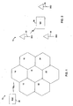
- FIG. 1 illustrates a wireless communication system 10 having multiple cells 12,14,16,18,20,22,24.
- the cells 12, 14, 16, 18, 20, 22, 24 communicate with BSC 26 via a radio air interface.
- Each of the cells 12, 14, 16, 18, 20, 22, 24 has a corresponding neighbor set, made up of cells within a geographical and/or transmission neighborhood.
- cell 18 has a neighborhood set including cells 12, 14, 16, 20, 22, 24.
- CDMA Code Division Multiple Access
- the IS-95 standard or the "TIA/EIA/IS-2000 Standards for cdma2000 Spread Spectrum Systems”
- PN Pseudorandom Noise
- FIG. 2 illustrates a portion of the system 10 of FIG. 1 , including base station 32, labeled BS1, in communication with MS 38.
- the BS1 32 is within cell 18 of FIG.1 .
- Two other base stations 34, 36, labeled BS2 and BS3, respectively, are within cells 16, 24, respectively.
- the radio air interface provides the medium for the Forward Link (FL) for communications from BS1 32 to MS 38, and the Reverse Link (RL) from MS 38 to BS1 32.
- FL Forward Link
- RL Reverse Link
- MS 38 may move within system 10 such that signal quality to and from BS1 32 deteriorates.
- the MS 38 sends transmissions on an access channel.
- the BS1 32, BS2 34, and BS3 36 send channel assignment messages on a paging channel.
- the channel assignment identifies the Walsh code index for each base station.
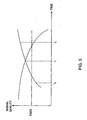
- FIG. 3 illustrates a plot of signal quality as measured at MS 38 for BS1 32 and BS2 34.
- the signal quality for BS2 34 begins to increase at time t0 and continues to increase above a threshold level, labeled T_ADD, by time t1.
- the threshold level, T_ADD provides a reference signal quality above which MS 38 is instructed to notify the base station to add a base station to its Active Set (AS).
- the AS is made up of base stations that are actively communicating with MS 38, both transmitting and receiving communications.
- the AS is typically selected from base stations that are in a Candidate Set (CS).
- the CS includes base stations that are candidates to become active communicators with MS 38.
- the CS is typically selected from base stations in the Neighbor Set (NS).
- SNR Signal to Noise Ratio
- the signal quality of BS2 34 is improving, the signal quality of BS1 32 is deteriorating.
- the increase in the energy level of the signals received from BS2 34 add to the deterioration of the signals from BS1 32, as the signal quality for a given base station is a comparison of the signal energy from that base station to all other signals present.
- MS 38 measures the signal energy of BS2 34 above T_ADD. This indicates to the MS 38 that appropriate action is required, i.e., is a trigger for hand-off.
- MS 38 transmits to BS1 32 and BSC 26 a Pilot Strength Measurement Message (PSMM) containing measurement information for both BS1 32 and BS2 34.
- PSMM Pilot Strength Measurement Message
- BSC 26 sets up a link from BSC 26 to BS2 34 for MS 38.
- the BSC 26 contains a selector.
- the BSC 26 sets up a communication link forming 'a "back haul" communication network between the BS1 32, BS2 34 and BSC 26 with respect to MS 38.
- BS1 32 sends a Handoff Direction Message (HDM) containing information identifying BS1 32 and BS2 34 and their associated code indices for the Forward Link (FL) channels from BS1 32 and BS2 34. This information allows MS 38 to receive and demodulate signals from both BS1 32 and BS2 34.
- HDM Handoff Direction Message
- MS 38 receives the HDM from BS1 32 and begins to demodulate signals from BS2 34 in addition to those from BS1 32. Note that in this example there is only one new base station involved in the hand-off. However, there may be any number of base stations involved in such a hand-off situation, wherein those base stations communicating with MS 38 form an AS. When the MS 38 receives signals, including symbols, from multiple base stations in the AS, MS 38 may combine these signals resulting in a stronger signal. The combination process is referred to as "soft combination" of the FL and is usually carried out in optimal ratio combining, i.e., with weighting based on signal quality. At time t6 the MS 38 sends an acknowledgement for the HDM received from BS1 32 or an Handoff Completion Message (HCM) indicating the successful completion of the handoff.
- HCM Handoff Completion Message
- a situation may arise wherein the signal quality of BS2 34 increases too quickly.
- the signal strength of BS2 34 with respect to that of BS1 32 encourages deterioration of the signal quality of BS1 32.
- the MS 38 is hindered from communicating with the infrastructure prior to receiving information necessary for hand-off, such as the Pseudorandom Noise (PN) offset necessary to identify BS2 34 or the channel used by BS2 34 for MS 38.
- PN Pseudorandom Noise
- hand-off prevents loss of the communication link.
- soft hand-off the mobile station simultaneously maintains connections with two or more base stations.
- the current location of the mobile station may be considered the source cell, while the next cell that the mobile station moves to may be referred to as the target cell.
- the mobile station uses a rake type receiver to demodulates the multiple signals received on the FL of the multiple base stations. The two signals are combined resulting in a composite signal with improved quality.
- each of the multiple base stations involved in soft hand-off demodulates the signal received separately, each sends the demodulated and decoded information to a BSC.
- the BSC contains a selector that selects the best frame from the multiple frames received.
- Other types of hand-off may be used for a variety of conditions and system requirements.
- the mobile station makes a measurement of the signal quality for the FL pilot signals from multiple mobile stations. This information is reported to the source base station. The signal qualities are compared to various thresholds to make decisions for adding base stations to the AS. If the signal quality of a given pilot is greater than a pilot detection threshold, T_ADD, then the pilot is added to the AS. Alternatively , the pilot may be added to the CS first and then to the AS. In effect, the threshold allows for transfer of the status of a base station from one set to another.
- T_ADD pilot detection threshold
- Call recovery provides information to the mobile station ahead of time, in the case when hand-off negotiation is not possible. Call recovery is initiated in a variety of situations.
- the mobile station and the base station use triggers to determine their proper operation.
- mobile stations operating within system 10 use a variety of thresholds for decision making with regard to what information is reported back to the base station.
- T_ADD indicates a signal quality level for adding a base station to the AS.
- T_DROP provides a signal quality level below which a base station will be dropped from the AS.
- T_DROP provides a signal quality level below which a base station will be dropped from the AS.
- the mobile station receives a signal that measures below T_DROP for a duration longer than T_TDROP, the mobile station reports this condition to the system through the existing AS.
- the base stations in the AS relay this information to a base station controller.
- a first type of call recovery trigger occurs when the FL signal quality is below a threshold level for a duration longer than another threshold.
- This type of trigger includes when the base station receives continuous Power Control (PC) requests from the mobile station to increase the transmit level at the base station.
- PC Power Control
- the base station is already transmitting to the mobile station at a maximum ceiling power level.
- the FL traffic transmission is maintained at a high level for a predetermined time period.
- the mobile station may send many requests to increase the power, i.e., UP commands. Alternately, the mobile station may report an abundance of erasures. An erasure occurs when more than a threshold level of bits are received without confidence of the intended value.
- the mobile station transmits messages indicating to the base station that its outer loop set-point is high or at its maximum allowed level, or at those levels for an extended time.
- a second type of trigger occurs when a certain response is expected from the mobile station, but no response, or a different response, is received.
- This type of trigger includes lack of acknowledgement from the mobile station to a message sent by the base station that requires an acknowledgement. The message may be re-sent a predetermined number of times prior to satisfying the trigger. This predetermined number may be fixed or variable and changeable over the air.
- the base station may receive repeated RL messages from the mobile station that require an acknowledgement, wherein the messages are received subsequent to base station transmission of an acknowledgement.
- a third type of trigger relates to low quality of the reverse link, e.g., when the Frame Error Rate (FER) of the RL is above a threshold level.
- the RL may be maintained at a high level for a predetermined time period.
- Still another situation may have a high RL set-point.
- the base station to be added to an AS also has call recovery triggers that initiate recovery action.
- the most significant trigger is a notification from the BSC that a potential problem exists with a given mobile station. On such an occurrence, the base station begins to search for signals from the mobile station.
- the mobile station may also use a variety of call recovery triggers to enter call recovery.
- a first type of trigger occurs when there are abnormal number of errors in the received signals. For example, FL erasures over a moving window may exceed a predetermined threshold level. For example , the threshold level is 12 consecutive frames experiencing erasure. In this case, the mobile station will turn off the transmitter portion of the mobile station, and may turn the transmitter back on when at least two FL consecutive frames have no erasures.
- a second type of recovery trigger for the mobile station occurs when the mobile station receives PC commands from the base instructing increases in power.
- the base station may be having difficulty receiving the RL signals due to large path losses from the mobile station.
- a third type of recovery trigger occurs when one or more RL messages that require acknowledgement from the base station are not being acknowledged. This is referred to as retransmission retry trigger. Similarly, there may be an inappropriate response or no response from the base station to a message from the mobile station. A similar type of trigger occurs on receipt of repeated FL messages requiring an acknowledgement, subsequent to the mobile station actually transmitting the acknowledgement.
- a fourth type of recovery trigger occurs when the mobile station transmits at a high level for a predetermined time period. In this case it is assumed that the RL is not getting through to the base station with sufficient energy.
- flexible thresholds are implemented for the one or multiple of the various call recovery triggers.
- the call recovery triggers may be based on multiple attempts to transmit within a system 10. These attempts are often made in the link layer between signaling and the physical link.
- the link layer is referred to as Layer 2, and is discussed hereinbelow with respect to PIG. 8.
- MS 38 performs a recovery procedure to maintain a call when the communication link, such as the FL, is deteriorating.
- a trigger often initiates a recovery operation, wherein the trigger indicates when a parameter or metric passes a threshold.
- These thresholds may be dynamic, adapting to conditions of the system 10 and environment. Similarly, the thresholds may be adjusted based on a history or statistical record of operation of the system 10.
- the number of repeated transmissions on the RL, or the time between consecutive erasures, or the disabling of MS 38 transmitter may be in response to an instruction transmitted from the system 10 infrastructure, such as BS1 32 and/or BSC 26.
- a fixed parameter is defined for the particular action, such as a specified maximum number of allowable re-transmissions.
- the mobile condition and/or location provides a trigger.
- the proximity of the current transmit level of MS 38 to a predetermined maximum value may trigger call recovery.
- Other triggers include the quality of the FL as measured by erasures of transmissions in the current AS, a deficit in inner loop power control, wherein the MS 38 desired SNR is different from that provided by the inner loop, etc. Still other examples may combine the specific parameter and the mobile condition as triggers.
- the system 10 infrastructure may provide the MS 38 with operational type information helpful in determining the thresholds of call recovery triggers, and may use such information in selecting fixed parameters provided to the MS 38 to use as trigger thresholds.
- An alternate example uses the loading of the RL to set and adjust thresholds.
- Still alternate examples may use the location of MS 38 within the system 10, such as the sector of a given cell.
- Still other examples consider the day of the week and/or time of day in coordination with known mobile traffic patterns. A combination of any of these mechanisms may also be implemented where applicable or needed.
- each base station, 32, 34, 36 transmits overhead information to mobile stations with which it communicates.
- the overhead information for each BS 32, 34, 36 includes its respective neighbor list.
- the neighbor list identifies the corresponding Pseudorandom Noise (PN) code offsets of the neighbors.
- PN Pseudorandom Noise
- BSC 26 responds to any of the variety of triggers by setting up a backhaul connection with BS1 32 and BS2 34.
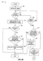
- method 100 of call recovery is initiated as illustrated in FIG. 6 .
- the particular signal quality plot for one example is illustrated in FIG. 5 .
- BS1 32 sends default channel assignments for the set of neighboring base station(s) to MS 38.
- the base stations in the neighbor set are recovery-capable units, having the necessary software and/or hardware to implement a call recovery and having coverage area(s) overlapping that of the base station sending the neighbor set.
- the default channel assignments identify the default channel code index used by base stations within the neighbor set, including the code for BS2 34.
- Each of the base stations in the neighbor set that are recovery-capable have a default spreading code that will be used to identify a mobile station in need of call recovery.
- the spreading code of one example is a specific Walsh code.
- the BS2 34 sends a retransmission retry trigger to the MS 38 at step 104.
- the retransmission retry trigger dictates the number of retries that the MS 38 is to allow prior to initiating call recovery operations.
- the BS1 32 determines if a recovery trigger has occurred at decision diamond 106. If a recovery trigger has not occurred, processing waits for occurrence of a trigger. On the occurrence of a trigger, processing continues to step 108 to instruct all base stations in the NS of BS1 32 to transmit on their respective default channels corresponding to the MS 38.
- each base station within the N S begins to transmit to the MS 38.
- the multiple transmissions provide a stronger FL signal at the MS 38 and a more reliable RL to BSC 26.
- the number of retries of an RL message, or the amount of time allowed for consecutive erasures are determined by the BSC 26 and provided to the MS 38 via radio link dedicated messages and broadcasts.
- An alternate example uses a fixed parameter, distinct from other parameters.
- One example incorporates a function of the mobile conditions. Mobile conditions may consider how close the actual transmission level of MS 38 is in comparison to a maximum transmit level. Similarly, another mobile condition considers the quality of the FL, such as erasures on the current AS. Still another mobile condition considers an inner loop deficit. The inner loop deficit is the difference between a target SNR and the SNR delivered by the inner loop PC. Another example combines the mobile condition with the type of transmission.
- the allowable number of retries may be adjusted according to statistics relating to dropped calls or troubled calls. For example, there may be an average number of retries above which a majority of troubled calls do not recover. Other considerations include the RL loading, the location of MS 38, and/or the time of day, or date. In the latter case, certain mobile traffic patterns affect the number of mobiles requiring a fast call recovery.
- the BSC 26 determines the current AS of MS at step 110.
- the BSC 26 then initializes an HDM timer at step 112 and transmits the HDM at step 114.
- the system 10 desires to move the communication links off the default channels.
- the default channels are available for use by any of the mobile stations within system 10 and therefore, use is to be optimized.
- MS 38 utilizes a given default channel, that channel is not available for use by another mobile station.
- the base stations in the NS are instructed to initiate transmissions on an alternate or new channel in parallel with the transmissions on the default channel. This is the initiation of a hand-off condition.
- step 120 If the BSC 26 has received a message from the MS 38 indicating the hand-off is complete at decision diamond 118, processing continues to step 120 to discontinue the MS 38 communication links with members of the NS on the default channels. Processing then continues to step 124. Conversely, if the hand-off complete message is not received, the BSC 26 checks if the HDM timer has expired at decision diamond 122. If the HDM timer has expired, the appropriate default channel terminates transmissions to MS 38, call recovery is cancelled at step 124, and usage of both the default channel and the new channel is discontinued at step 125. The normal operation resumes at step 126. If the timer has not expired at decision diamond 122, processing returns to wait for the hand-off complete message from MS 38 at decision diamond 118.
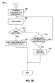
- FIG. 6B details a portion of method 100, wherein the step 110 is illustrated as initializing a timer at step 130.
- the BSC 26 checks for a PSMM from MS 38 at decision diamond 132. If the PSMM has been received, processing continues to step 134 to set the AS to include neighbors included in the PSMM. If no PSMM is received, processing continues to decision diamond 138 to determine if the timer (initialized in step 130) has expired. If the timer has expired, processing continues to decision diamond 144. If the timer has not expired, processing returns to decision diamond 132.
- BSC 26 determines if there are any neighbors not included in the PSMM that have acquired the MS 38 signal(s) at decision diamond 140. These neighbors are referred to as Hearing Neighbors (HN), and are added to the AS at step 142. Processing then returns to step 112 of FIG. 6A .
- HN Hearing Neighbors
- BSC 26 determines, at decision diamond 144, if any neighbors acquired the RL MS 38 signal(s), i.e., HN. In this case, the AS is set to include these HN at step 146. If no HN is found at decision diamond 144, then call recovery terminates at step 148 and the call is terminated.
- the method determines if the transmitter of MS 38 is turned off. If the transmitter is off, the BSC 26 instructs the MS 38 to turn the transmitter on at step 110.
- a mobile station call recovery method 200 for one example is illustrated in FIG. 7 .
- the MS 38 communicates with base stations in the AS(0). This identifies the current AS. If a recovery trigger has occurred at decision diamond 204, processing continues to decision diamond 208.
- the recovery trigger could be one of those discussed hereinabove, or an alternate indication that the MS 38 requires a rescue type operation, i.e., MS 38 is probably losing the FL communication link. If no trigger occurs, normal operation resumes at step 206.
- Decision diamond 208 determines if the transmitter of MS 38 is enabled. If the transmitter is enabled, processing continues to step 214, and if not, the MS 38 checks for a trigger condition at decision diamond 210.
- step 214 If a trigger condition exists that indicates MS 38 is to disable the transmitter, then appropriate action is taken at step 212 and processing continues to step 214. If no trigger indicates that the transmitter is to be disabled, then processing continues to step 214. At step 214 a wait timer is set. The wait timer is checked at decision diamond 216, and on expiration the recovery timer is started at step 218. If the wait timer has not expired, then processing continues to determine if the MS 38 has returned to a normal operating mode at decision diamond 222. Normal operation continues from step 206, else processing returns to wait for expiration of the wait timer.
- step 220 the transmitter is enabled.
- the MS 38 transmits a predetermined preamble for time period Y.
- the preamble provides information about the MS 38 transmission but no actual data or symbols.
- the MS 38 transmits the PSMM information at step 228.
- decision diamond 2208 if the HDM is received or if some acknowledgement is received confirming the PSMM, the MS 38 proceeds to wait a predetermined time period X, after which the AS is updated. If no HDM or PSMM acknowledgement is received at decision diamond 230, processing continues to decision diamond 232 to check that the PSMM has not been transmitted more than a maximum allowable number of times. If the PSMM can be resent, i.e., the maximum has not been reached, processing returns to step 228 and the PSMM is resent. However, if the maximum has been reached, processing continues to step 236 and the call recovery is terminated.
- BSC 26 notifies all of the recovery-capable neighbors of BS1 32 of a potential problem.
- the BSC instructs the MS 38 to turn on the transmitter portion of MS 38 and instructs the base station(s) in the neighbor set to listen for the MS 38.
- On detection or acquisition of a signal from MS 38 each base station in the neighbor set transmits a report.
- the reports are received from a subset of base stations, wherein the subset may include all base stations in the neighbor set or a portion of base stations.
- the BSC 26 notifies the MS 38 of the default channels of each base station in the subset.
- the base stations of the subset then use the appropriate default channel to initiate communication with MS 38.
- a subset of the neighbor set is determined based on a most recently transmitted PSMM.
- call recovery is thwarted.
- the BSC 26 sets up a backhaul network with BS3 36 and BS3 36 begins transmissions to MS 38 on a default channel.
- MS 38 assumes that communication will be established with BS2 34 for call recovery and prepares to except on a different default channel. The excess transmission from BS3 36 is wasted and effectively creates more noise in the system 10.
- a timer may be used to delay such initiation subsequent to occurrence of a call recovery trigger.
- the time period of the timer may be sets by the BSC 26.
- the MS 38 transmits a preamble on a RL pilot channel.
- the preamble includes a call recovery message.
- the preamble is a predetermined constant that may be set by BSC 26.
- the preamble is a variable length determined by the system operator.
- MS 38 sends a message regarding the FL change(s).
- the message may be a PSMM.
- the message may be sent a number of times to ensure receipt by BS2 34.
- a call recovery method is based on the radio transmission environment of the source cell base station.
- the BSC 26 When the number of neighbors that are recovery-capable is small, e.g. 2, the BSC 26 will instruct all of the neighbors to transmit on respective default channels. The AS is updated and the MS 38 transmitter is enabled without a delay.
- the BSC 26 will instruct the neighbors to listen for signals from MS 38. After a delay incurred in waiting for the neighbors to report on whether they can receive signals from MS 38, those hearing neighbors are instructed to use the default channels.
- those base stations identified by the PSMM are instructed to use default channels. Note that when the FL is operating properly, as defined by a fixed number of consecutive good frames, the PC commands sent via the PC subchannel are considered valid.
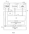
- FIG. 8 illustrates the architecture of wireless communication system 10 of FIG. 1 in a layer structure format.
- the architecture 700 includes three layers: a signaling layer 702; a link layer 704; and a physical layer 706.
- the signaling layer 702 provides upper layer signaling 708, data services 710, and voice services 712.
- the signaling layer 702 provides for voice, packet data, simple circuit data, and simultaneous voice and packet data services. Protocols and services are provided at this layer corresponding to the bottom two layers.
- the link layer 704 is subdivided into a Link Access Control (LAC) sublayer 714 and a Medium Access Control (MAC) sublayer 716.
- LAC Link Access Control
- MAC Medium Access Control
- the link layer 704 serves as an interface between the upper level protocols and applications of the signaling layer 702 and the physical layer 706.
- the MAC sublayer 716 further includes multiplexing and Quality of Service (QoS) delivery block 722.
- QoS Quality of Service
- the link layer 704 couples the signal layer 702 to the physical layer 706.
- the physical layer 706 is made up of the physical channel 724 of transmission.
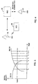
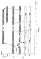
- FIG. 9 provides a timing scenario for operation of the system 10 of FIG. 1 according to one example.
- the horizontal axis represents time and the vertical axis represents the various channels used for transmission.
- the source cell base station, BS1 32 is provided in the middle, where information is transmitted via a traffic channel to MS 38.
- Two channels are illustrated for the MS 38: a transmission channel Tx; and a receiver channel Rx.
- Two scenarios are illustrated for the receiver channel: Rx 1 and Rx 2 .
- the default channel and a new channel are both illustrated.
- the new channel is the channel to be used for communication with MS 38 after hand-off.
- MS 38 begins with MS 38 receiving transmissions from a first AS, identified as AS(0).
- the MS 38 is simultaneously transmitting on a traffic channel for the source cell BS1 32.
- a call recovery trigger occurs.
- Both MS 38 and BS1 32 recognize the trigger.
- the trigger may be a common event, such as continued PC requests from MS 38 to BS1 32 to increase the transmit power of the FL, or may be separate events for the MS 38 and the BS1 32.
- the MS 38 and the BS1 32 may not recognize the trigger(s) at the same time. Often the MS 38 may be in a position to recognize a trigger prior to BS1 32 during FL failures.
- the BSC 26 initiates a default channel transmission from the neighbor BS2 34.
- BS2 34 begins transmitting on the default channel to MS 38.
- the transmission is parallel with the same transmission from BS1 32.
- the MS 38 disables the transmitter for a predetermined wait time period.
- the wait period ends and the MS 38 transmits the preamble for a time period Y.
- the AS of MS 38 is changed from AS(0) to AS(1).
- the base stations identified in the AS(1) are all the base stations cited in the last PSMM.
- the AS(1) may be all of the neighbors of BS1 32 and BS1 32 itself.
- the preamble terminates, and the MS 28 begins transmitting the current PSMM.
- the BS1 32 and the BS2 34 transmit an HDM at time t6.
- the HDM signals the change of the AS to AS(2) at time t8.
- a next PSMM is sent at time t7, wherein PSMM are sent periodically or continuously to identify signals received at the MS 38.
- the BS2 34 begins transmission on the new channel for MS 38.
- the MS 38 transmits an HCM which triggers the termination of transmissions for MS 38 on the default channel at time t9.
- the HCM is transmitted periodically or continuously until its correct reception is acknowledged by the base station.
- call recovery begins at time t2 and terminates at time t9.
- BS2 34 is current source cell base station for MS 38.
- receiver channel Rx 2 An alternate scenario is illustrated for receiver channel Rx 2 .
- the AS(0) remains active until time t5.
- the MS 38 continues to receive from AS(0) for a predetermined time period X, after which there is a change to AS(1).
- AS(1) a predetermined time period
- This allows for extra time for the base station side to determine on a subset of the recovery-capable neighbors of BS1 32 for the transmission to MS 38 for recovery.
- time t8 there is a subsequent change in response to the HDM from AS(1) to AS(2).
- This scenario corresponds to the method wherein only those neighbors able to acquire signals from the MS 38 are instructed to transmit via respective default channels.
- the MS 28 must determine an initial transmission power level.
- the system 10 of FIG. 1 uses a closed loop power control for adjustment of transmission power levels.
- Alternate embodiments may use an additional open loop method of power control.
- Open loop refers to transmitter (either mobile or base station)-controlled operation where the receiver is not directly involved.
- a particular reverse link open loop power control calls for the mobile to adjust reverse link transmit power based on the power level of signals received from the base station via the forward link.
- Closed loop power control expands open loop operation whereby the receiver actively participates in making the power adjustment decision. For example, for RL closed loop power control the base station compares the power level of signals received from a given mobile to a threshold value.
- the base station then instructs the mobile to increase or decrease the reverse link transmit power based on the comparison.
- the mobile monitors the power level of signals received on the FL, and provides feedback on the quality of the FL to the base station. Closed loop operation is used to compensate for power fluctuations associated with fading, such as Raleigh fading, of a given link.
- the MS 38 begins transmitting at an initial power level.
- the RL transmit power level may resume from just prior to disabling the transmitter of MS 38.
- the power level may remain at this initial level until closed-loop power control resumes.
- the power level is initiated at the last level prior to disabling the transmitter and then gradually increased at a predetermined rate until power control resumes.
- the speed of the increase is typically set by the BS1 32 and/or BS2 34, and may be a fixed value or variable. The increases continue until the RL closed loop power control resumes.
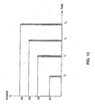
- FIG. 10 illustrates the power adjustments according to this example.
- the horizontal axis represents time and the vertical axis represents the transmission power level.
- the transmit power is at an initial power level.
- the transmit power is increased by a predetermined increment value.
- the increment value may be a fixed value or may be variable, either increasing or decreasing with increasing time.
- the increment value is adaptive and responds to the conditions of the system 10, wherein the increment value may increase or decrease from one time period to a subsequent time period. Finally; a predetermined maximum transmit power level may be reached after a predetermined number of time periods. The transmit power then is at a ceiling awaiting the resumption of the closed loop power control.
- the initial transmit power is based on the signal quality of pilots received.
- the signal quality is measured by a pilot E c /I 0 or a pilot E c for the intended AS.
- T x + R x k + y t
- the determination of an initial transmit power applies the ⁇ of the previous transmissions to the new transmissions.
- a wireless apparatus MS 38 operating in system 10 of FIG. 1 such as a cell phone or a personal digital assistant (PDA), is illustrated in FIG. 11 .
- the MS 38 includes an antenna 300 for transmitting and receiving.
- the antenna 300 is coupled to a duplexor 302 for isolating the receiver path from the transmitter path.
- the duplexor is coupled to the receiver circuitry 308 forming the receiver path and is coupled to an amplifier 304 and transmit circuitry 306 forming the transmitter path.
- the amplifier 304 is further coupled to a power adjust unit 310 that provides the control of the amplifier 304.
- the amplifier 304 receives the transmission signals from the transmit circuitry 306.
- Received signals via antenna 300 are provided to a power control unit 314 that implements a closed loop power control scheme.
- the power control unit 314 is coupled to a communication bus 318.
- the communication bus 318 provides a common connection between modules within the MS 38.
- The' communication bus 318 is further coupled to a memory 322 and a recovery adjusts unit 316.
- the memory 322 stores computer readable instructions for a variety of operations and functions applicable to MS 38.
- the processor 320 performs the instructions stored in memory 322.
- the power control unit generates a PC signal to power adjust 310 via multiplexor 312.
- the power adjusts 310 then transfers the PC signal as an amplification level to the amplifier 304.
- the MS 38 may disable the transmitter.
- a hand-off complete signal is provided to the recovery adjust unit 316.
- the hand-off complete signal instructs the recovery adjust unit 316 to generate a predetermined PC signal.
- the PC signal so generated may implement any of the schemes for initial RL transmit power generation discussed hereinabove, or may implement an alternate method.
- the hand-off complete signal is also provided to control the multiplexor 312. Subsequent to call recovery, the PC signal generated by the recovery adjust unit 316 is forwarded to the power adjust unit 310. In parallel, closed loop power control begins.
- the hand-off complete signal is negated, and the multiplexor 312 selects the PC signal generated by power control unit 314 to provide to power adjust 310.
- the operation of recovery adjust unit 316 may be performed by the microprocessor 320 operating on software instructions or may be implemented in hardware for efficient, reliable operation.
- special events include a variety of conditions and procedures that may cause false triggers to occur. In other words, special events may produce a situation where a call recovery trigger occurs, but the call is not distressed.
- One special event is a mobile position locator search.
- the MS 38 is instructed to search on an alternate frequency for a Global Position System (GPS) signal.
- GPS Global Position System
- the GPS provides a location of the MS 38 or partial information of the location of the MS 38.
- the mobile position locator search is done periodically or aperiodically.
- the MS 38 has a priori information regarding the timing of such searches.
- Other events may include candidate frequency search in preparation for an inter-frequency hard handoff where the mobile station tunes to another frequency to search for signal from base stations on a different frequency.
- a special event is a candidate frequency search, wherein MS 38 tunes to a different frequency to look for signals from neighbor base stations on that frequency. This allows a better transition between coverage on different frequencies, e.g. switching between a Personal Communication System (PCS) frequency and a cellular frequency.
- PCS Personal Communication System
- the MS 38 On occurrence of this type of mobile station initiated special event, the MS 38 notifies the source cell BS1 32 to ignore triggers with respect to MS 38 during a specific time period or until further notification.
- the source cell base station such as BS1 32, grants the permission for the event and notifies the MS 38 the timing of the event, including at least when the event is to begin and the length of time allocated to the event.
- the MS 38 and the base stations in its AS disable the call recovery trigger(s) from initiating a call recovery during the special event.
- MS 38 notifies the BS1 32 of an upcoming special event or a set of these special events.
- the BS1 32 may approve the special event, veto the event, or reschedule the event. Again, this provides the MS 38 and the base stations in its AS with sufficient information to disable the call recovery triggers during the special event.
- the mobile station and the infrastructure prearrange potential rescue base stations.
- the source cell base station contacts all recovery-capable neighbors as potential rescuers.
- a recovery-capable neighbor has a predefined default channel adapted for soft hand-off with a mobile station. The default channel is only used temporarily during the initial portion of hand-off.
- Each rescue base station is instructed to use a default channel for rescue transmissions. The rescue transmission is considered a call recovery operation.
- the mobile station establishes a soft hand-off with rescue base station, wherein the FL uses the default channel.
- the rescue base station then initiates transmissions on an alternate channel.
- the rescue base station discontinues use of the default channel with respect to transmissions to the mobile station.
- the source cell base station provides the mobile station with the list of recovery-capable neighbors as overhead during transmissions and prior to development of the communication link problem. In this way, for situations where the FL is lost prior to receipt of hand-off information, the mobile station has sufficient information to proceed with a hand-off.
- more than one default channel is assigned to the neighbor BS2 34.
- the use of multiple default or rescue channels increases the call recovery capability of a system 10.
- Each neighbor is then able to contribute to call recovery of more than one mobile station, such as MS 38.
- the source cell BS1 32 provides to MS 38 an identifier corresponding to the multiple channels' associated with BS2 34.
- the MS 38 and BS2 34 each store a deterministic function, such as a hash function, to map the identifiers to a specific channel.
- the use of a hash function in particular is a pseudorandom procedure.
- an electronic serial number is assigned to the MS 38.
- the electronic serial number may be stored in the MS 38 or may be provided to the MS 38 on call recovery.
- the source cell BS1 32 provides the electronic serial number of MS 38 to the BS2 34.
- the BS2 34 and the MS 38 both apply the predetermined function to calculate the appropriate default channel.
- a hash function for a data structure allows recognition of a key word in a set of words using exactly one probe into the data structure.
- a hash function maps its argument to a result of predetermined type.
- a hash function is deterministic and stateless. That is, the return value depends only on the argument, and equal arguments yield equal results. It is important for hash function to minimize collisions, wherein a collision is defined as two different arguments that hash to the same value. It is also important that the distribution of hash values be uniform; that is, the probability that a hash function returns any particular value of predetermined type should be roughly the same as the probability that it returns any other value. In alternate examples, other forms of cryptographic functions may be implemented for identification of the multiple default channels on call recovery.
- DSP digital signal processor
- ASIC application specific integrated circuit
- FPGA field programmable gate array
- a processor executing a set of firmware instructions, any conventional programmable software module and a processor, or any combination thereof designed to perform the functions described herein.
- the processor may advantageously be a microprocessor, but in the alternative, the processor may be any conventional processor, controller, microcontroller, or state machine.
- the software modules could reside in RAM memory, flash memory, ROM memory, EPROM memory, EEPROM memory, registers, hard disk, a removable disk, a CD-ROM, or any other form of storage medium known in the art.
- the processor may reside in an ASIC (not shown).
- the ASIC may reside in a telephone (not shown).
- the processor may reside in a telephone.
- the processor may be implemented as a combination of a DSP and a microprocessor, or as two microprocessors in conjunction with a DSP core, etc.
Landscapes
- Engineering & Computer Science (AREA)
- Computer Networks & Wireless Communication (AREA)
- Signal Processing (AREA)
- Mobile Radio Communication Systems (AREA)
Claims (2)
- Dispositif sans fil (38) comprenant :un circuit émetteur (306) ;caractérisé par :une unité d'ajustement de récupération (316) actionnable, en réponse à un signal d'achèvement de transfert fourni par le dispositif sans fil à l'unité d'ajustement de récupération à la suite d'une opération de récupération d'appel, pour générer une instruction de commande de puissance prédéterminée, l'instruction de commande de puissance étant basée sur au moins l'un parmile niveau de puissance d'émission avant la récupération d'appel ; oula puissance totale reçue ; oubasée sur la qualité de signal d'un ou plusieurs signaux pilotes de liaison directe reçus ; etune unité d'ajustement de puissance (310) couplée à l'unité d'ajustement de récupération (316) et au circuit émetteur (306), l'unité d'ajustement de puissance (310) étant actionnable pour ajuster le circuit émetteur (306) en réponse à l'instruction de commande de puissance.
- Dispositif (38) selon la revendication 1, dans lequel l'unité d'ajustement de récupération (316) est actionnable par un microprocesseur (320), le microprocesseur (320) étant actionnable par des instructions logicielles ou mis en oeuvre par du matériel.
Applications Claiming Priority (5)
| Application Number | Priority Date | Filing Date | Title |
|---|---|---|---|
| US25153700P | 2000-12-05 | 2000-12-05 | |
| US251537P | 2000-12-05 | ||
| US09/738,016 US7945266B2 (en) | 2000-12-05 | 2000-12-15 | Method and apparatus for call recovery in a wireless communication system |
| US738016 | 2000-12-15 | ||
| PCT/US2001/044566 WO2002047402A2 (fr) | 2000-12-05 | 2001-11-29 | Procede et appareil de recuperation d'appels dans un systeme de communication sans fil |
Publications (2)
| Publication Number | Publication Date |
|---|---|
| EP1346594A2 EP1346594A2 (fr) | 2003-09-24 |
| EP1346594B1 true EP1346594B1 (fr) | 2012-10-10 |
Family
ID=26941681
Family Applications (1)
| Application Number | Title | Priority Date | Filing Date |
|---|---|---|---|
| EP01270068A Expired - Lifetime EP1346594B1 (fr) | 2000-12-05 | 2001-11-29 | Procede et appareil de recuperation d'appels dans un systeme de communication sans fil |
Country Status (18)
| Country | Link |
|---|---|
| US (1) | US7945266B2 (fr) |
| EP (1) | EP1346594B1 (fr) |
| JP (2) | JP4202132B2 (fr) |
| KR (2) | KR100918214B1 (fr) |
| CN (2) | CN1303840C (fr) |
| AU (2) | AU1792202A (fr) |
| BR (1) | BR0115931A (fr) |
| CA (1) | CA2430864A1 (fr) |
| DK (1) | DK1346594T3 (fr) |
| ES (1) | ES2393977T3 (fr) |
| HK (1) | HK1063554A1 (fr) |
| IL (1) | IL155894A0 (fr) |
| MX (1) | MXPA03004992A (fr) |
| NO (1) | NO20032524L (fr) |
| PT (1) | PT1346594E (fr) |
| RU (2) | RU2301505C2 (fr) |
| TW (1) | TW560213B (fr) |
| WO (1) | WO2002047402A2 (fr) |
Families Citing this family (28)
| Publication number | Priority date | Publication date | Assignee | Title |
|---|---|---|---|---|
| US7567781B2 (en) | 2001-01-05 | 2009-07-28 | Qualcomm, Incorporated | Method and apparatus for power level adjustment in a wireless communication system |
| US7945266B2 (en) | 2000-12-05 | 2011-05-17 | Qualcomm Incorporated | Method and apparatus for call recovery in a wireless communication system |
| UA73813C2 (en) * | 2000-12-05 | 2005-09-15 | Qualcomm Inc | Method (variants) and device for transmitter reinitialization in a wireless communication system |
| US6314126B1 (en) * | 2001-01-12 | 2001-11-06 | Linex Technologies, Inc. | Spread-spectrum handoff and source congestion avoidance system and method |
| US7082303B2 (en) * | 2001-06-12 | 2006-07-25 | Motorola, Inc. | Method for supporting rescue channels in a communications system |
| US7047010B2 (en) * | 2001-12-21 | 2006-05-16 | Samsung Electronics Co., Ltd. | System and method for providing rescue channel communications between base stations in a wireless communication system |
| US6993334B2 (en) * | 2002-04-30 | 2006-01-31 | Qualcomm Inc. | Idle handoff with neighbor list channel replacement |
| FR2847110A1 (fr) * | 2002-11-08 | 2004-05-14 | Melco Mobile Comm Europ | Procede de reduction de zones mortes dans un systeme umts, systeme de telecommunication mobile et station mobile correspondants |
| FR2847108A1 (fr) * | 2002-11-08 | 2004-05-14 | Mitsubishi Electric Telecom Eu | Procede et systeme de reduction des zones mortes dans un systeme umts |
| JP4173405B2 (ja) * | 2003-05-29 | 2008-10-29 | 京セラ株式会社 | 通信端末の圏外判定方法、通信端末 |
| WO2005009069A1 (fr) * | 2003-07-10 | 2005-01-27 | Telefonaktiebolaget Lm Ericsson (Publ) | Gestion de liaison radio fondee sur le resultat de demande de retransmission |
| US7738901B2 (en) | 2003-07-10 | 2010-06-15 | Telefonaktiebolaget Lm Ericsson (Publ) | Secondary link power control in a wireless communication network |
| KR100810247B1 (ko) * | 2004-03-05 | 2008-03-06 | 삼성전자주식회사 | 직교 주파수 분할 다중 접속 시스템에서 채널 할당 방법및 장치 |
| EP1587336A1 (fr) * | 2004-04-14 | 2005-10-19 | Motorola, Inc. | Unité distante, appareil, système de communication cellulaire et son procédé de mise en oeuvre |
| US7643419B2 (en) * | 2004-05-07 | 2010-01-05 | Interdigital Technology Corporation | Method and apparatus for implementing a data lifespan timer for enhanced dedicated channel transmissions |
| US7979025B2 (en) * | 2005-04-05 | 2011-07-12 | Vodafone Group, Plc | Method and apparatus for handover in a wireless communication device between wireless domains |
| CN100479612C (zh) * | 2007-01-22 | 2009-04-15 | 华为技术有限公司 | 一种语音通信的方法及其装置 |
| JP4367493B2 (ja) * | 2007-02-02 | 2009-11-18 | ソニー株式会社 | 無線通信システム、無線通信装置及び無線通信方法、並びにコンピュータ・プログラム |
| US9066253B2 (en) * | 2008-09-10 | 2015-06-23 | Intel Mobile Communications GmbH | System and method for reduced interruption time in mobile communications |
| WO2011117764A1 (fr) * | 2010-03-26 | 2011-09-29 | Koninklijke Philips Electronics N.V. | Evaluation de la liaison avant la fin d'une connexion alternée pendant des transferts de réseau hétérogène |
| SG188377A1 (en) | 2010-06-04 | 2013-04-30 | Univ Texas | Methods and apparatuses for relaying data in a wireless communications system |
| US9794949B2 (en) | 2010-07-30 | 2017-10-17 | Board Of Regents, The University Of Texas System | Distributed rate allocation and collision detection in wireless networks |
| WO2012122508A2 (fr) | 2011-03-09 | 2012-09-13 | Board Of Regents | Système, procédé et produit programme informatique de routage sur un réseau |
| US8831591B2 (en) * | 2012-04-30 | 2014-09-09 | Verizon Patent And Licensing Inc. | Automatic reconnection of a dropped call |
| KR20140088375A (ko) * | 2013-01-02 | 2014-07-10 | 삼성전자주식회사 | 무선 통신 시스템에서 기지국 간 무선 링크 복구를 위한 방법 및 장치 |
| US8977270B2 (en) * | 2013-02-27 | 2015-03-10 | Qualcomm Incorporated | Updating a base reference power for high speed data resumption |
| US9838948B2 (en) * | 2014-07-29 | 2017-12-05 | Aruba Networks, Inc. | Deep packet inspection (DPI) aware client steering and load balancing in wireless local area network (WLAN) infrastructure |
| US11512016B2 (en) | 2017-03-22 | 2022-11-29 | Corning Incorporated | Methods of separating a glass web |
Family Cites Families (56)
| Publication number | Priority date | Publication date | Assignee | Title |
|---|---|---|---|---|
| US233982A (en) * | 1880-11-02 | Device for converting motion | ||
| US624994A (en) * | 1899-05-16 | taylor | ||
| US2047402A (en) * | 1933-07-12 | 1936-07-14 | Norman M Barker | Momentum measuring apparatus for golf practice and the like |
| US4901307A (en) * | 1986-10-17 | 1990-02-13 | Qualcomm, Inc. | Spread spectrum multiple access communication system using satellite or terrestrial repeaters |
| US5101501A (en) * | 1989-11-07 | 1992-03-31 | Qualcomm Incorporated | Method and system for providing a soft handoff in communications in a cdma cellular telephone system |
| US5103459B1 (en) * | 1990-06-25 | 1999-07-06 | Qualcomm Inc | System and method for generating signal waveforms in a cdma cellular telephone system |
| US5267261A (en) * | 1992-03-05 | 1993-11-30 | Qualcomm Incorporated | Mobile station assisted soft handoff in a CDMA cellular communications system |
| JPH06216901A (ja) | 1993-01-13 | 1994-08-05 | Nec Corp | 衛星通信方式 |
| EP0624994B1 (fr) | 1993-05-12 | 2000-04-05 | Ntt Mobile Communications Network Inc. | Méthode pour le transfert d'appel et appareil mobile pour système de communication à spectre étalé |
| NZ276006A (en) * | 1993-11-01 | 1997-11-24 | Ericsson Telefon Ab L M | Cellular radio: scanning of neighbouring control channels |
| US6088590A (en) * | 1993-11-01 | 2000-07-11 | Omnipoint Corporation | Method and system for mobile controlled handoff and link maintenance in spread spectrum communication |
| US5809430A (en) * | 1994-06-03 | 1998-09-15 | Motorola, Inc. | Method and apparatus for base selection in a communication system |
| GB2299732B (en) * | 1995-04-06 | 1999-08-11 | Nokia Mobile Phones Ltd | A Wireless Base Station |
| US5907542A (en) * | 1996-04-15 | 1999-05-25 | Ascom Tech Ag | Dynamic assignment of signalling virtual channels for wireless ATM systems |
| CN1100457C (zh) * | 1996-07-29 | 2003-01-29 | 艾利森电话股份有限公司 | 在无线电信网络中释放话音信道的方法 |
| JPH10112877A (ja) | 1996-10-04 | 1998-04-28 | Nippon Denki Ido Tsushin Kk | 携帯電話装置 |
| US6021328A (en) | 1996-12-19 | 2000-02-01 | Northern Telecom Limited | Radio link quality handoff trigger |
| US5854785A (en) | 1996-12-19 | 1998-12-29 | Motorola, Inc. | System method and wireless communication device for soft handoff |
| US5999816A (en) * | 1997-02-18 | 1999-12-07 | Qualcomm Incorporated | Method and apparatus for performing mobile assisted hard handoff between communication systems |
| US5913167A (en) * | 1997-02-28 | 1999-06-15 | Motorola, Inc. | Method for transferring a communication link in a wireless communication system |
| KR100240451B1 (ko) * | 1997-05-22 | 2000-01-15 | 서평원 | 기지국 사이의 연속 하드 핸드오프 감소 방법 |
| US5940743A (en) * | 1997-06-05 | 1999-08-17 | Nokia Mobile Phones Limited | Power control of mobile station transmissions during handoff in a cellular system |
| US6160999A (en) * | 1997-08-18 | 2000-12-12 | Nortel Networks Limited | Wireless communication system providing improved forward link management and method of operation |
| KR100276698B1 (ko) * | 1997-11-17 | 2001-02-01 | 정선종 | 코드분할다중접속셀룰러이동통신시스템에서소프트핸드오프시의순방향링크전력제어방법및장치 |
| KR100304924B1 (ko) * | 1997-12-30 | 2001-11-22 | 서평원 | 코드분할다중접속셀룰러시스템의주파수간핸드오프제어방법 |
| FI105436B (fi) * | 1998-02-11 | 2000-08-15 | Nokia Networks Oy | Menetelmä tietoliikennekanavan vaihtamiseksi matkaviestinjärjestelmässä |
| US6144861A (en) * | 1998-04-07 | 2000-11-07 | Telefonaktiebolaget Lm Ericsson | Downlink power control in a cellular mobile radio communications system |
| KR100318940B1 (ko) * | 1998-04-17 | 2002-04-22 | 윤종용 | 이동통신시스템에서의호장애시재접속방법 |
| JP3229937B2 (ja) * | 1998-05-26 | 2001-11-19 | 沖電気工業株式会社 | Phs端末装置および子機間直接通信方法 |
| JP3240998B2 (ja) | 1998-07-27 | 2001-12-25 | 日本電気株式会社 | 送信パワー制御回路 |
| US6633554B1 (en) * | 1998-09-01 | 2003-10-14 | Samsung Electronics Co., Ltd. | System and method for soft handoff setup during system access idle handoff in a wireless network |
| US6360100B1 (en) | 1998-09-22 | 2002-03-19 | Qualcomm Incorporated | Method for robust handoff in wireless communication system |
| US6785249B2 (en) * | 1998-10-05 | 2004-08-31 | Qualcomm, Incorporated | Method and apparatus for detecting forward and reverse link imbalance in digital cellular communication systems |
| GB9823467D0 (en) | 1998-10-28 | 1998-12-23 | Koninkl Philips Electronics Nv | Radio communication system |
| JP2000151504A (ja) | 1998-11-18 | 2000-05-30 | Nec Saitama Ltd | 基地局無線装置及びその制御方法 |
| KR100277104B1 (ko) * | 1998-12-03 | 2001-01-15 | 윤종용 | 이동통신시스템에서의호장애시호재접속방법 |
| JP2000354267A (ja) * | 1999-04-07 | 2000-12-19 | Toshiba Corp | ハンドオーバ要求機能を備えた移動通信端末装置、ハンドオーバ制御装置、ハンドオーバ制御方法及びハンドオーバ制御方法を記憶した記憶媒体 |
| KR100342565B1 (ko) * | 1999-04-20 | 2002-07-04 | 윤종용 | 코드분할 다중접속 시스템의 단말기에서 단절된 호 복원 방법및 그 통보 방법 |
| US6233455B1 (en) * | 1999-05-03 | 2001-05-15 | Nortel Networks Limited | Method for utilizing negative T—COMP to improve handoff reliability |
| US6445918B1 (en) * | 1999-11-01 | 2002-09-03 | Telefonaktiebolaget L M Ericsson (Publ) | Method and system for saving dropped calls |
| KR100469734B1 (ko) * | 1999-12-07 | 2005-02-02 | 삼성전자주식회사 | 이동통신시스템에서 통화단절을 복구하는 방법 |
| US6445921B1 (en) * | 1999-12-20 | 2002-09-03 | Koninklijke Philips Electronics N.V. | Call re-establishment for a dual mode telephone |
| US6337983B1 (en) * | 2000-06-21 | 2002-01-08 | Motorola, Inc. | Method for autonomous handoff in a wireless communication system |
| US6706420B1 (en) | 2000-07-06 | 2004-03-16 | Honeywell International Inc. | Electroless platinum-rhodium alloy plating |
| KR100593866B1 (ko) | 2000-10-17 | 2006-06-30 | 가부시키가이샤 덴소 | 통신 시스템을 위한 순방향 링크 기반의 구제 채널 방법및 장치 |
| US7054631B2 (en) * | 2000-10-23 | 2006-05-30 | Denso Corporation | Enhancement of soft handoff in a mobile wireless network through the use of dynamic information feedback from mobile users |
| US6968186B2 (en) * | 2000-11-30 | 2005-11-22 | Lucent Technologies Inc. | System and method for preventing dropped calls |
| US20020097780A1 (en) * | 2000-11-30 | 2002-07-25 | Odenwalder Joseph P. | Preamble generation |
| US7006821B2 (en) * | 2000-12-04 | 2006-02-28 | Denso Corporation | Method and apparatus for dynamically determining a mobile station's active set during a connection rescue procedure |
| RU2285337C2 (ru) | 2000-12-05 | 2006-10-10 | Квэлкомм Инкорпорейтед | Способ и устройство для регулировки уровня мощности в системе беспроводной связи |
| US7945266B2 (en) | 2000-12-05 | 2011-05-17 | Qualcomm Incorporated | Method and apparatus for call recovery in a wireless communication system |
| US7260401B2 (en) * | 2000-12-05 | 2007-08-21 | Qualcomm Incorporated | Method and apparatus for flexible call recovery in a wireless communication system |
| US6842625B2 (en) * | 2001-09-27 | 2005-01-11 | L-3 Communications Corporation | Method for autonomous frequency management for reliable data communications |
| US7409448B2 (en) * | 2003-11-25 | 2008-08-05 | International Business Machines Corporation | Method, system, and storage medium for resolving contention issues during channel program execution |
| US20050150137A1 (en) * | 2004-01-08 | 2005-07-14 | William Steidle | Hang tabs for footwear |
| US7409138B1 (en) | 2007-03-12 | 2008-08-05 | Corning Cable Systems Llc | Fiber optic local convergence points for multiple dwelling units |
-
2000
- 2000-12-15 US US09/738,016 patent/US7945266B2/en not_active Expired - Fee Related
-
2001
- 2001-11-29 IL IL15589401A patent/IL155894A0/xx unknown
- 2001-11-29 KR KR1020037007414A patent/KR100918214B1/ko active IP Right Grant
- 2001-11-29 RU RU2003120072/09A patent/RU2301505C2/ru not_active IP Right Cessation
- 2001-11-29 MX MXPA03004992A patent/MXPA03004992A/es active IP Right Grant
- 2001-11-29 CN CNB018200141A patent/CN1303840C/zh not_active Expired - Lifetime
- 2001-11-29 AU AU1792202A patent/AU1792202A/xx active Pending
- 2001-11-29 BR BRPI0115931-3A patent/BR0115931A/pt not_active IP Right Cessation
- 2001-11-29 WO PCT/US2001/044566 patent/WO2002047402A2/fr active IP Right Grant
- 2001-11-29 PT PT1270068T patent/PT1346594E/pt unknown
- 2001-11-29 CN CN2010102004704A patent/CN101925092A/zh active Pending
- 2001-11-29 AU AU2002217922A patent/AU2002217922B2/en not_active Ceased
- 2001-11-29 CA CA002430864A patent/CA2430864A1/fr not_active Abandoned
- 2001-11-29 ES ES01270068T patent/ES2393977T3/es not_active Expired - Lifetime
- 2001-11-29 EP EP01270068A patent/EP1346594B1/fr not_active Expired - Lifetime
- 2001-11-29 KR KR1020097004426A patent/KR101025463B1/ko active IP Right Grant
- 2001-11-29 JP JP2002548998A patent/JP4202132B2/ja not_active Expired - Lifetime
- 2001-11-29 DK DK01270068.8T patent/DK1346594T3/da active
- 2001-12-05 TW TW090130101A patent/TW560213B/zh not_active IP Right Cessation
-
2003
- 2003-06-04 NO NO20032524A patent/NO20032524L/no not_active Application Discontinuation
-
2004
- 2004-08-20 HK HK04106233A patent/HK1063554A1/xx not_active IP Right Cessation
-
2007
- 2007-02-09 RU RU2007105080/09A patent/RU2007105080A/ru not_active Application Discontinuation
-
2008
- 2008-01-31 JP JP2008021844A patent/JP4713601B2/ja not_active Expired - Lifetime
Also Published As
| Publication number | Publication date |
|---|---|
| US20020077104A1 (en) | 2002-06-20 |
| BR0115931A (pt) | 2006-05-02 |
| CA2430864A1 (fr) | 2002-06-13 |
| CN1505905A (zh) | 2004-06-16 |
| MXPA03004992A (es) | 2004-02-12 |
| ES2393977T3 (es) | 2013-01-03 |
| AU2002217922B2 (en) | 2007-07-12 |
| AU1792202A (en) | 2002-06-18 |
| JP2004536476A (ja) | 2004-12-02 |
| RU2301505C2 (ru) | 2007-06-20 |
| WO2002047402A3 (fr) | 2003-02-27 |
| NO20032524L (no) | 2003-07-31 |
| KR20090027778A (ko) | 2009-03-17 |
| CN1303840C (zh) | 2007-03-07 |
| JP4713601B2 (ja) | 2011-06-29 |
| RU2007105080A (ru) | 2008-08-20 |
| NO20032524D0 (no) | 2003-06-04 |
| TW560213B (en) | 2003-11-01 |
| RU2003120072A (ru) | 2005-02-10 |
| EP1346594A2 (fr) | 2003-09-24 |
| PT1346594E (pt) | 2012-12-24 |
| HK1063554A1 (en) | 2004-12-31 |
| JP2008199608A (ja) | 2008-08-28 |
| WO2002047402A2 (fr) | 2002-06-13 |
| IL155894A0 (en) | 2003-12-23 |
| CN101925092A (zh) | 2010-12-22 |
| US7945266B2 (en) | 2011-05-17 |
| DK1346594T3 (da) | 2012-11-12 |
| KR101025463B1 (ko) | 2011-04-04 |
| KR100918214B1 (ko) | 2009-09-21 |
| JP4202132B2 (ja) | 2008-12-24 |
| KR20030059306A (ko) | 2003-07-07 |
Similar Documents
| Publication | Publication Date | Title |
|---|---|---|
| EP1346594B1 (fr) | Procede et appareil de recuperation d'appels dans un systeme de communication sans fil | |
| US7567781B2 (en) | Method and apparatus for power level adjustment in a wireless communication system | |
| US7260401B2 (en) | Method and apparatus for flexible call recovery in a wireless communication system | |
| JP6026475B2 (ja) | 無線通信システムにおけるパワーレベル調節のための方法および装置 | |
| AU2002217922A1 (en) | Method and apparatus for call recovery in a wireless communication system | |
| EP1212918B1 (fr) | Mesure inter-frequence et transfert pour radio communications | |
| JP3574945B2 (ja) | 無線通信システムにおける周波数間ハンドオフのための方法および装置 | |
| RU2496264C2 (ru) | Конфигурация улучшений смены обслуживающей соты hs-dsch | |
| AU2007221910A1 (en) | Method and apparatus for power level adjustment in a wireless communication system | |
| TWI235614B (en) | Method and apparatus for power level adjustment in a wireless communication system | |
| UA79233C2 (en) | Wireless communication device for cdma communication systems | |
| ZA200201554B (en) | Inter-frequency measurement and handover for wireless communications. |
Legal Events
| Date | Code | Title | Description |
|---|---|---|---|
| PUAI | Public reference made under article 153(3) epc to a published international application that has entered the european phase |
Free format text: ORIGINAL CODE: 0009012 |
|
| 17P | Request for examination filed |
Effective date: 20030526 |
|
| AK | Designated contracting states |
Kind code of ref document: A2 Designated state(s): AT BE CH CY DE DK ES FI FR GB GR IE IT LI LU MC NL PT SE TR |
|
| AX | Request for extension of the european patent |
Extension state: AL LT LV MK RO SI |
|
| REG | Reference to a national code |
Ref country code: DE Ref legal event code: R079 Ref document number: 60147206 Country of ref document: DE Free format text: PREVIOUS MAIN CLASS: H04Q0007380000 Ipc: H04W0036000000 |
|
| RIC1 | Information provided on ipc code assigned before grant |
Ipc: H04W 52/44 20090101ALI20120110BHEP Ipc: H04W 36/00 20090101AFI20120110BHEP Ipc: H04W 52/40 20090101ALN20120110BHEP Ipc: H04W 76/02 20090101ALN20120110BHEP |
|
| GRAP | Despatch of communication of intention to grant a patent |
Free format text: ORIGINAL CODE: EPIDOSNIGR1 |
|
| RIC1 | Information provided on ipc code assigned before grant |
Ipc: H04W 52/40 20090101ALN20120119BHEP Ipc: H04W 36/00 20090101AFI20120119BHEP Ipc: H04W 76/02 20090101ALN20120119BHEP Ipc: H04W 52/44 20090101ALI20120119BHEP |
|
| GRAS | Grant fee paid |
Free format text: ORIGINAL CODE: EPIDOSNIGR3 |
|
| GRAA | (expected) grant |
Free format text: ORIGINAL CODE: 0009210 |
|
| AK | Designated contracting states |
Kind code of ref document: B1 Designated state(s): AT BE CH CY DE DK ES FI FR GB GR IE IT LI LU MC NL PT SE TR |
|
| REG | Reference to a national code |
Ref country code: GB Ref legal event code: FG4D |
|
| REG | Reference to a national code |
Ref country code: CH Ref legal event code: EP Ref country code: AT Ref legal event code: REF Ref document number: 579421 Country of ref document: AT Kind code of ref document: T Effective date: 20121015 |
|
| REG | Reference to a national code |
Ref country code: IE Ref legal event code: FG4D |
|
| REG | Reference to a national code |
Ref country code: DK Ref legal event code: T3 |
|
| REG | Reference to a national code |
Ref country code: CH Ref legal event code: NV Representative=s name: R. A. EGLI AND CO. PATENTANWAELTE, CH |
|
| REG | Reference to a national code |
Ref country code: DE Ref legal event code: R096 Ref document number: 60147206 Country of ref document: DE Effective date: 20121206 |
|
| REG | Reference to a national code |
Ref country code: SE Ref legal event code: TRGR |
|
| REG | Reference to a national code |
Ref country code: PT Ref legal event code: SC4A Free format text: AVAILABILITY OF NATIONAL TRANSLATION Effective date: 20121207 |
|
| REG | Reference to a national code |
Ref country code: NL Ref legal event code: T3 |
|
| REG | Reference to a national code |
Ref country code: ES Ref legal event code: FG2A Ref document number: 2393977 Country of ref document: ES Kind code of ref document: T3 Effective date: 20130103 |
|
| REG | Reference to a national code |
Ref country code: GR Ref legal event code: EP Ref document number: 20120402763 Country of ref document: GR Effective date: 20130122 |
|
| PG25 | Lapsed in a contracting state [announced via postgrant information from national office to epo] |
Ref country code: CY Free format text: LAPSE BECAUSE OF FAILURE TO SUBMIT A TRANSLATION OF THE DESCRIPTION OR TO PAY THE FEE WITHIN THE PRESCRIBED TIME-LIMIT Effective date: 20121010 |
|
| PLBE | No opposition filed within time limit |
Free format text: ORIGINAL CODE: 0009261 |
|
| STAA | Information on the status of an ep patent application or granted ep patent |
Free format text: STATUS: NO OPPOSITION FILED WITHIN TIME LIMIT |
|
| 26N | No opposition filed |
Effective date: 20130711 |
|
| REG | Reference to a national code |
Ref country code: DE Ref legal event code: R097 Ref document number: 60147206 Country of ref document: DE Effective date: 20130711 |
|
| PG25 | Lapsed in a contracting state [announced via postgrant information from national office to epo] |
Ref country code: MC Free format text: LAPSE BECAUSE OF NON-PAYMENT OF DUE FEES Effective date: 20121130 Ref country code: TR Free format text: LAPSE BECAUSE OF FAILURE TO SUBMIT A TRANSLATION OF THE DESCRIPTION OR TO PAY THE FEE WITHIN THE PRESCRIBED TIME-LIMIT Effective date: 20121010 |
|
| PG25 | Lapsed in a contracting state [announced via postgrant information from national office to epo] |
Ref country code: LU Free format text: LAPSE BECAUSE OF NON-PAYMENT OF DUE FEES Effective date: 20121129 |
|
| REG | Reference to a national code |
Ref country code: FR Ref legal event code: PLFP Year of fee payment: 15 |
|
| REG | Reference to a national code |
Ref country code: FR Ref legal event code: PLFP Year of fee payment: 16 |
|
| REG | Reference to a national code |
Ref country code: FR Ref legal event code: PLFP Year of fee payment: 17 |
|
| REG | Reference to a national code |
Ref country code: FR Ref legal event code: PLFP Year of fee payment: 18 |
|
| PGFP | Annual fee paid to national office [announced via postgrant information from national office to epo] |
Ref country code: NL Payment date: 20201015 Year of fee payment: 20 |
|
| PGFP | Annual fee paid to national office [announced via postgrant information from national office to epo] |
Ref country code: PT Payment date: 20201027 Year of fee payment: 20 Ref country code: FR Payment date: 20201023 Year of fee payment: 20 Ref country code: CH Payment date: 20201015 Year of fee payment: 20 Ref country code: AT Payment date: 20201027 Year of fee payment: 20 Ref country code: IE Payment date: 20201027 Year of fee payment: 20 Ref country code: ES Payment date: 20201202 Year of fee payment: 20 Ref country code: FI Payment date: 20201026 Year of fee payment: 20 Ref country code: DE Payment date: 20201013 Year of fee payment: 20 Ref country code: DK Payment date: 20201026 Year of fee payment: 20 Ref country code: SE Payment date: 20201109 Year of fee payment: 20 Ref country code: IT Payment date: 20201117 Year of fee payment: 20 Ref country code: GR Payment date: 20201026 Year of fee payment: 20 Ref country code: GB Payment date: 20201029 Year of fee payment: 20 |
|
| PGFP | Annual fee paid to national office [announced via postgrant information from national office to epo] |
Ref country code: BE Payment date: 20201015 Year of fee payment: 20 |
|
| REG | Reference to a national code |
Ref country code: DE Ref legal event code: R071 Ref document number: 60147206 Country of ref document: DE |
|
| REG | Reference to a national code |
Ref country code: NL Ref legal event code: MK Effective date: 20211128 |
|
| REG | Reference to a national code |
Ref country code: DK Ref legal event code: EUP Expiry date: 20211129 |
|
| REG | Reference to a national code |
Ref country code: FI Ref legal event code: MAE |
|
| REG | Reference to a national code |
Ref country code: GB Ref legal event code: PE20 Expiry date: 20211128 |
|
| REG | Reference to a national code |
Ref country code: SE Ref legal event code: EUG |
|
| REG | Reference to a national code |
Ref country code: IE Ref legal event code: MK9A |
|
| REG | Reference to a national code |
Ref country code: BE Ref legal event code: MK Effective date: 20211129 |
|
| REG | Reference to a national code |
Ref country code: AT Ref legal event code: MK07 Ref document number: 579421 Country of ref document: AT Kind code of ref document: T Effective date: 20211129 |
|
| PG25 | Lapsed in a contracting state [announced via postgrant information from national office to epo] |
Ref country code: PT Free format text: LAPSE BECAUSE OF EXPIRATION OF PROTECTION Effective date: 20211207 Ref country code: GB Free format text: LAPSE BECAUSE OF EXPIRATION OF PROTECTION Effective date: 20211128 Ref country code: IE Free format text: LAPSE BECAUSE OF EXPIRATION OF PROTECTION Effective date: 20211129 |
|
| REG | Reference to a national code |
Ref country code: ES Ref legal event code: FD2A Effective date: 20220405 |
|
| PG25 | Lapsed in a contracting state [announced via postgrant information from national office to epo] |
Ref country code: ES Free format text: LAPSE BECAUSE OF EXPIRATION OF PROTECTION Effective date: 20211130 |