EP1346094B1 - Verfahren zur steuerung der schleudergeschwindigkeit einer trommelwaschmaschine - Google Patents
Verfahren zur steuerung der schleudergeschwindigkeit einer trommelwaschmaschine Download PDFInfo
- Publication number
- EP1346094B1 EP1346094B1 EP01998682A EP01998682A EP1346094B1 EP 1346094 B1 EP1346094 B1 EP 1346094B1 EP 01998682 A EP01998682 A EP 01998682A EP 01998682 A EP01998682 A EP 01998682A EP 1346094 B1 EP1346094 B1 EP 1346094B1
- Authority
- EP
- European Patent Office
- Prior art keywords
- lead angle
- voltage
- maximum value
- maximum
- drum
- Prior art date
- Legal status (The legal status is an assumption and is not a legal conclusion. Google has not performed a legal analysis and makes no representation as to the accuracy of the status listed.)
- Expired - Lifetime
Links
Images


Classifications
-
- D—TEXTILES; PAPER
- D06—TREATMENT OF TEXTILES OR THE LIKE; LAUNDERING; FLEXIBLE MATERIALS NOT OTHERWISE PROVIDED FOR
- D06F—LAUNDERING, DRYING, IRONING, PRESSING OR FOLDING TEXTILE ARTICLES
- D06F33/00—Control of operations performed in washing machines or washer-dryers
- D06F33/30—Control of washing machines characterised by the purpose or target of the control
- D06F33/48—Preventing or reducing imbalance or noise
-
- D—TEXTILES; PAPER
- D06—TREATMENT OF TEXTILES OR THE LIKE; LAUNDERING; FLEXIBLE MATERIALS NOT OTHERWISE PROVIDED FOR
- D06F—LAUNDERING, DRYING, IRONING, PRESSING OR FOLDING TEXTILE ARTICLES
- D06F2103/00—Parameters monitored or detected for the control of domestic laundry washing machines, washer-dryers or laundry dryers
-
- D—TEXTILES; PAPER
- D06—TREATMENT OF TEXTILES OR THE LIKE; LAUNDERING; FLEXIBLE MATERIALS NOT OTHERWISE PROVIDED FOR
- D06F—LAUNDERING, DRYING, IRONING, PRESSING OR FOLDING TEXTILE ARTICLES
- D06F2105/00—Systems or parameters controlled or affected by the control systems of washing machines, washer-dryers or laundry dryers
-
- D—TEXTILES; PAPER
- D06—TREATMENT OF TEXTILES OR THE LIKE; LAUNDERING; FLEXIBLE MATERIALS NOT OTHERWISE PROVIDED FOR
- D06F—LAUNDERING, DRYING, IRONING, PRESSING OR FOLDING TEXTILE ARTICLES
- D06F2105/00—Systems or parameters controlled or affected by the control systems of washing machines, washer-dryers or laundry dryers
- D06F2105/46—Drum speed; Actuation of motors, e.g. starting or interrupting
- D06F2105/48—Drum speed
Definitions
- the present invention relates to a method for controlling a spinning speed of a drum washing machine, and more particularly, to a method for controlling a spinning speed of a drum washing machine, in which an upper limit of a lead angle is made to vary with a voltage applied to the washing machine, to control an allowable eccentricity of laundry at a maximum speed to be below a preset value, for securing a system stability.
- washing machine there are a pulsator type washing machine in which a washing tub rotates in a vertical position, and a drum type washing machine in which the washing tub rotates in a horizontal position.
- the drum washing type carrying out washing by using a friction of laundry and a drum rotated as a driving power of a motor is received, gives almost no damage to the laundry, causes no entangling of the laundry, and can provide pounding and rubbing effects.
- D1 discloses an out of balance control for a laundry machine according to the preamble of independent claim 1.
- a current signal that is proportionate to a current drawn by a motor that rotates a perforated drum into which fabric goods are loaded is used as an input signal.
- the input to the control is a signal that reflects variations in torque required to rotate the drum. The magnitude of these variations is proportional to load unbalance that can cause radial displacement of the drum.
- the real time signal is averaged.
- a differential amplifier subtracts the averaged signal from the real time signal providing an unbalance torque signal of alternating polarity. When the unbalance torque signal exceeds a given magnitude, reflecting the maximum permissible centrifugal force to be generated by load unbalance, an unbalance control signal is generated that is responsive to reduce the rotational speed of the drum.
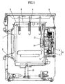
- FIG. 1 illustrates a section of one exemplary related art direct coupling type drum washing machine, provided with a tub 3 inside of a cabinet 5, and a drum 9 inside of the tub 3.
- drum shaft 13 fitted to the drum 9 for transmission of a driving power of the motor 6 to the drum 9.
- bearings 12 in front and rear of the drum shaft 13, and a bearing housing in a central part of a rear wall of the tub 3.
- stator 7 of the direct coupling type motor 6 fixed to a rear wall part of the tub 3, and a rotor 8 of the direct coupling type motor 6 on the drum shaft 13 together with the stator 7. According to this, the drum 9 is directly coupled to, and rotated with the rotor 8.
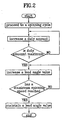
- revolution speed control of the drum 9 is carried out during spinning as follows.
- the motor sensor 11 keeps to detect a revolution speed of the rotor 8, and transmits to a controller (not shown), and the controller compares if the revolution speed of the rotor 8 is reached to a desired revolution rate.
- revolution speed of the rotor 8 is reached to a revolution speed (for an example, 110rpm) the laundry is stuck to, and does not fall off from, an inside wall of the drum 9, an eccentricity of the laundry is detected, and if the eccentricity is determined to be higher than an allowable value, the drum is rotated again after the drum is stopped, and if the eccentricity is determined to be lower than an allowable value, the revolution speed of the rotor 8 is increased gradually.
- a revolution speed for an example, 110rpm
- the revolution speed of the rotor 8 is increased step by step until the revolution speed reached to a maximum spinning speed, when the revolution speed of the rotor 8 is increased no more, but is maintained.
- the revolution speed of the rotor 8 is controlled by means of a duty value and a lead angle.
- the duty value is increased by PWM (Pulse Width Modulation) to a revolution speed (for an example, 1000rpm) below the maximum revolution speed (for an example, 1400rpm), and remained portion of the revolution speed required to reach to the maximum revolution speed is increased by controlling the lead angle for bringing the revolution speed into line with a desired maximum revolution rate.
- PWM Pulse Width Modulation
- the control of the motor 6 speed by controlling the duty value and the lead angle is made as follows.
- the duty value varied by PWM control, is a value varied up to 0-250, and the revolution speed of the rotor 8 is varied with the value, such that the greater the duty value, the higher the revolution of the rotor.
- the lead angle is one for controlling a spinning speed by controlling a phase difference of a current and a voltage, of which purpose lies on bringing waveforms of the voltage and the current into conformity by making the voltage applied earlier than the current within 0-75° phase taking a fact that the phase of the current is later than the voltage into account, and it is favorable that the waveforms of the voltage and the current are in conformity in view of power consumption.
- the related art direct coupling type drum washing machine has the following problems in the method for controlling the spinning speed.
- a maximum value of the lead angle is controlled to be below a preset value (for an example; 65°).
- the lead angle value is set to a value greater by a certain extent than an actual lead angle required for reaching to the maximum spinning speed when the rated voltage and eccentricity are normal.
- the spinning revolution speed is varied with the applied voltage, such that the higher the applied voltage, the higher the spinning revolution rate.
- the eccentricity is greater than a certain amount (for an example, 300g) under a state the drum 9 is reached to the maximum revolution speed, an excessive load is applied to the entire washing machine system due to the excessive eccentricity over the regular allowable value; which at the end weakens a rigidity as an overstrain is given to the entire system, such as motor, and the like.
- a certain amount for an example, 300g
- An object of the present invention is for achieving a system stability improvement in a drum washing machine by reducing an eccentricity of laundry allowed when a maximum spinning speed is reached to be below a preset value even if a voltage higher than a rated voltage is applied, by designing an upper limit of the lead angle is varied with the applied voltage.
- the present invention provides a method for controlling a spinning speed of a drum washing machine characterized in that a received voltage is sensed, and a maximum value of a lead angle is varied with a size of the received voltage.
- FIG. 3 illustrates a flow chart for showing the steps of a controlling method in accordance with a preferred embodiment of the present invention
- FIG. 4 illustrates a table showing a comparison of allowable eccentricities at maximum speeds for a maximum lead angle for a voltage of the present invention and for a maximum lead angle in the related art.
- the present invention suggests sensing received voltage and setting a maximum lead angle to be varied with the received voltage in a method for controlling a spinning speed of a drum washing machine.
- a maximum lead angle is smaller than a maximum lead angle at reception of the rated voltage, and when the received voltage is lower than the rated voltage, the maximum lead angle is greater than the maximum lead angle at reception of the rated voltage.
- the speed of the rotor is brought to be the same with the maximum spinning speed by increasing the duty value through PWM (Pulse Width Modulation), to increase a revolution speed of the rotor to a preset speed (for an example; 1,000rpm) below a maximum speed (for an example; 1,400rpm), and by increasing a remained portion for reaching to the maximum speed through controlling the lead angle.
- PWM Pulse Width Modulation
- the washing machine since the washing machine has a voltage sensing circuit for preventing an appliance from being operated in a case an irregular voltage, out of an operative range of the appliance, is received, the received voltage is sensed by the voltage sensing circuit and transmitted to the controller.
- the controller maintains, or changes, the maximum value of the lead angle according to a size of the received voltage sensed at the voltage sensing circuit.
- the spinning is basically progressed as the lead angle set to the rated voltage is maintained, when a voltage, higher or lower than the rated voltage, is received, the spinning is progressed in a state the value is changed to the maximum value of the lead angle for the received voltage with reference to a maximum data of lead angles set differently for voltage values (or voltage ranges).
- the maximum value of the lead angle is 57°.
- the maximum value of the lead angle is 65°
- the maximum value of the lead angle is 47°.
- the maximum value of the lead angle is 65° even in a case a voltage higher than the 261V of the rated voltage is received in the related art, which lead angle has the allowable eccentricity of 750g that is excessive, the excessive eccentricity causes an excessive load on the entire system during the spinning maximum speed is reached.
- the maximum lead angle value is changed to 47° with reference to the maximum limited lead angle data for received voltages in a case a voltage higher than the 261V is received in the present invention, no excessive load is applied to the entire system because the allowable eccentricity is below 300g at the time of the maximum spinning speed even if the lead angle is increased to a maximum.
- maximum values of the lead angles are fixed for different voltages such that the spinning speed can reach to the maximum speed only in a state the eccentricity is 300g regardless of any received voltages, thereby applying no excessive load to the system.
- the present invention senses the received voltage, and varies a maximum value of the lead angle with reference to a size of the voltage, so that the maximum load applied to an entire system, such as motor, and the like, is within a stable range even if the voltage varies.
- the present invention can secure a stability of system, such as motor, even if any voltage is applied thereto during spinning, because the allowable eccentricity does not exceed a preset value (for an example: 300g) when the maximum speed is reached, leading the maximum load applied to the system, such as motor, to be always below a preset value, too.
- a preset value for an example: 300g
- the embodiment of the present invention takes the drum washing machine as an example, of course, the technical aspect of the present invention is applicable to other types of washing machines, such as a pulsator type, and the like.
- the present invention makes an eccentricity of the laundry allowable at a maximum spinning speed to be below a preset value even if a voltage higher than a rated voltage is received.
- the present invention is made to achieve system stability improvement by maintaining a load applied to the motor or the like of the drum washing machine to be below a preset value.
- the embodiment of the present invention takes a drum washing machine as an example
- the technical aspect of the present invention is of course applicable to other types of washing machines, such as a pulsator type washing machine.
Landscapes
- Engineering & Computer Science (AREA)
- Textile Engineering (AREA)
- Control Of Washing Machine And Dryer (AREA)
- Accessory Of Washing/Drying Machine, Commercial Washing/Drying Machine, Other Washing/Drying Machine (AREA)
Claims (7)
- Verfahren zum Steuern einer Drehzahl einer Trommelwaschmaschine mit den Schritten des Zuführens einer Spannung zu einem Motor zum Drehen der Trommel auf eine gewünschte Drehzahl,
dadurch gekennzeichnet, dass das Verfahren des Weiteren Folgendes umfasst:Erfassen einer empfangenen Spannung, die in die Trommelwaschmaschine eingespeist wird;Einstellen eines Höchstwertes eines Vorlaufwinkels entsprechend der empfangenen Spannung; undSteuern einer in den Motor eingespeisten Spannung entsprechend dem Höchstwert des Vorlaufwinkels derart, dass eine auf ein Gesamtsystem wirkende Last innerhalb eines stabilen Bereichs liegt. - Verfahren gemäß Anspruch 1, des Weiteren umfassend das Steuern einer Drehzahl eines Rotors entsprechend der Änderung eines Arbeitswertes durch Impulsbreitenmodulation (IBM) zum Steuern der Drehzahl der Trommelwaschmaschine.
- Verfahren gemäß Anspruch 1 oder 2, des Weiteren umfassend das Detektieren des Höchstwertes eines Vorlaufwinkels unter den Höchstwertdaten des Vorlaufwinkels, die spannungsabhängig unterschiedlich in einer Steuerung gespeichert sind.
- Verfahren gemäß einem der vorangehenden Ansprüche, des Weiteren umfassend das Vergleichen der empfangenen Spannung mit einer Nennspannung.
- Verfahren gemäß Anspruch 4, wobei der Höchstwert des Vorlaufwinkels eingestellt wird, wenn die empfangene Spannung höher ist als die Nennspannung, derart, dass der Höchstwert des Vorlaufwinkels kleiner ist als der Höchstwert des Vorlaufwinkels bei Empfang der Nennspannung.
- Verfahren gemäß Anspruch 4, wobei der Höchstwert des Vorlaufwinkels eingestellt wird, wenn die empfangene Spannung kleiner ist als die Nennspannung, derart, dass der Höchstwert des Vorlaufwinkels größer ist als der Höchstwert des Vorlaufwinkels bei Empfang der Nennspannung.
- Verfahren gemäß Anspruch 4 bis 6, wobei eine Größe des Höchstwertes des Vorlaufwinkels für die empfangene Spannung entsprechend einer Differenz zwischen der empfangenen Spannung und der Nennspannung eingestellt wird.
Applications Claiming Priority (3)
| Application Number | Priority Date | Filing Date | Title |
|---|---|---|---|
| KR2000072545 | 2000-12-01 | ||
| KR1020000072545A KR100786059B1 (ko) | 2000-12-01 | 2000-12-01 | 드럼세탁기의 탈수속도 제어방법 |
| PCT/KR2001/002075 WO2002044459A1 (en) | 2000-12-01 | 2001-11-30 | Method for controlling spinning speed in drum-type washing machine |
Publications (3)
| Publication Number | Publication Date |
|---|---|
| EP1346094A1 EP1346094A1 (de) | 2003-09-24 |
| EP1346094A4 EP1346094A4 (de) | 2004-03-24 |
| EP1346094B1 true EP1346094B1 (de) | 2007-01-10 |
Family
ID=19702571
Family Applications (1)
| Application Number | Title | Priority Date | Filing Date |
|---|---|---|---|
| EP01998682A Expired - Lifetime EP1346094B1 (de) | 2000-12-01 | 2001-11-30 | Verfahren zur steuerung der schleudergeschwindigkeit einer trommelwaschmaschine |
Country Status (8)
| Country | Link |
|---|---|
| US (1) | US7168118B2 (de) |
| EP (1) | EP1346094B1 (de) |
| JP (2) | JP4142434B2 (de) |
| KR (1) | KR100786059B1 (de) |
| CN (1) | CN1256477C (de) |
| AU (2) | AU2002221176B2 (de) |
| DE (1) | DE60125979T2 (de) |
| WO (1) | WO2002044459A1 (de) |
Families Citing this family (16)
| Publication number | Priority date | Publication date | Assignee | Title |
|---|---|---|---|---|
| KR100786059B1 (ko) * | 2000-12-01 | 2007-12-17 | 엘지전자 주식회사 | 드럼세탁기의 탈수속도 제어방법 |
| JP3986470B2 (ja) * | 2003-06-18 | 2007-10-03 | 三洋電機株式会社 | ドラム式洗濯機 |
| GB2410848A (en) * | 2004-02-05 | 2005-08-10 | Dyson Ltd | Voltage compensation in switched reluctance motor |
| BRPI0402937A (pt) * | 2004-07-08 | 2006-02-21 | Multibras Eletrodomesticos Sa | método para reduzir o consumo de energia em uma máquina lavadora de roupas |
| DE602005016124D1 (de) * | 2004-07-21 | 2009-10-01 | Arcelik Anonim Sirketi Tuzla | Geschirrspülmaschine mit pulsweitenmodulatorsteuerung |
| US8042211B2 (en) * | 2005-08-16 | 2011-10-25 | Whirlpool Corporation | Method of detecting an off-balance condition of a clothes load in a washing machine |
| KR100712267B1 (ko) * | 2006-02-21 | 2007-04-27 | 주식회사 대우일렉트로닉스 | 드럼 세탁기 편심량 측정 방법 |
| KR20100045316A (ko) * | 2008-10-23 | 2010-05-03 | 엘지전자 주식회사 | 세탁기 |
| JP5535165B2 (ja) * | 2011-09-26 | 2014-07-02 | 株式会社東芝 | 半導体装置及びモータ駆動装置 |
| EP2669419B1 (de) * | 2012-05-18 | 2016-11-16 | Samsung Electronics Co., Ltd | Waschmaschine |
| CN105063955B (zh) * | 2015-08-05 | 2018-01-16 | 无锡小天鹅股份有限公司 | 洗衣机的控制方法和装置 |
| CN107190462B (zh) * | 2017-05-08 | 2020-02-21 | 无锡飞翎电子有限公司 | 洗衣机、洗衣机的撞桶检测方法以及装置 |
| JP7010609B2 (ja) * | 2017-07-12 | 2022-02-10 | 東芝ライフスタイル株式会社 | 洗濯機 |
| CN112709045A (zh) * | 2019-10-08 | 2021-04-27 | 无锡飞翎电子有限公司 | 洗衣机的控制方法、装置和洗衣机 |
| CN114687128B (zh) * | 2021-11-23 | 2025-11-25 | 合肥海尔滚筒洗衣机有限公司 | 一种洗衣机脱水控制方法及洗衣机 |
| US12618181B2 (en) | 2023-09-29 | 2026-05-05 | Haier Us Appliance Solutions, Inc. | Calibration cycles in washing machine appliances |
Family Cites Families (25)
| Publication number | Priority date | Publication date | Assignee | Title |
|---|---|---|---|---|
| US3596159A (en) * | 1968-03-22 | 1971-07-27 | Janome Sewing Machine Co Ltd | Speed control circuit for a single-phase motor,using a thyristor |
| US3612970A (en) * | 1970-08-31 | 1971-10-12 | Mini Ind Constructillor | Automatic-control system for the angular speed of a synchronous motor |
| SU635591A1 (ru) * | 1972-01-31 | 1978-11-30 | Научно-Исследовательский Институт Постоянного Тока | Способ автоматического регулировани выходного напр жени инвертора |
| GB1531336A (en) * | 1976-07-16 | 1978-11-08 | Mullard Ltd | Motor speed control circuits |
| JPS5852436B2 (ja) * | 1977-09-28 | 1983-11-22 | 三菱電機株式会社 | 半導体整流装置 |
| JPS5549990A (en) * | 1978-10-02 | 1980-04-11 | Fanuc Ltd | Drive system for dirrect current motor |
| US4451823A (en) * | 1981-08-07 | 1984-05-29 | Dart Controls, Inc. | Overload sensing circuit for a motor |
| US4481786A (en) * | 1982-06-04 | 1984-11-13 | Whirlpool Corporation | Electronic control for a domestic appliance |
| GB8324780D0 (en) * | 1983-09-15 | 1983-10-19 | Unsworth P J | Controller for induction motors |
| US4633158A (en) * | 1983-11-05 | 1986-12-30 | Kabushiki Kaisha Toshiba | Control system for an AC motor |
| JPS6225894A (ja) * | 1985-07-25 | 1987-02-03 | Silver Seiko Ltd | ステツピングモ−タの駆動装置 |
| US4765161A (en) * | 1987-10-19 | 1988-08-23 | American Laundry Machinery, Inc. | Out-of-balance control for laundry machines |
| DE4336349A1 (de) * | 1993-10-25 | 1995-04-27 | Bosch Siemens Hausgeraete | Verfahren zum Bestimmen der Masse von nasser Wäsche in einer Wäschetrommel |
| DE4336350A1 (de) * | 1993-10-25 | 1995-04-27 | Bosch Siemens Hausgeraete | Verfahren zum Bestimmen der Wäschemenge in einer Wäschebehandlungsmaschine |
| DE4342274A1 (de) | 1993-12-10 | 1995-06-14 | Bosch Siemens Hausgeraete | Automatisch gesteuerte Waschmaschine |
| US5471127A (en) * | 1994-05-04 | 1995-11-28 | Energy Reduction International Ltd. | Induction motor control |
| JP3230392B2 (ja) * | 1994-10-06 | 2001-11-19 | 株式会社明電舎 | サイリスタ整流器 |
| KR960034546A (ko) * | 1995-03-24 | 1996-10-24 | 구자홍 | 세탁기의 직류 전동기 제어 방법 |
| US5767653A (en) * | 1995-10-24 | 1998-06-16 | Micro Linear Corporation | Variable speed AC induction motor controller |
| US5875103A (en) * | 1995-12-22 | 1999-02-23 | Electronic Measurements, Inc. | Full range soft-switching DC-DC converter |
| US5808441A (en) * | 1996-06-10 | 1998-09-15 | Tecumseh Products Company | Microprocessor based motor control system with phase difference detection |
| JP3182382B2 (ja) * | 1997-09-10 | 2001-07-03 | 三洋電機株式会社 | 遠心脱水装置 |
| JPH11104392A (ja) * | 1997-10-06 | 1999-04-20 | Matsushita Electric Ind Co Ltd | 洗濯機 |
| KR19990075671A (ko) * | 1998-03-23 | 1999-10-15 | 구자홍 | 오픈루프 구간의 제어방법 |
| KR100786059B1 (ko) * | 2000-12-01 | 2007-12-17 | 엘지전자 주식회사 | 드럼세탁기의 탈수속도 제어방법 |
-
2000
- 2000-12-01 KR KR1020000072545A patent/KR100786059B1/ko not_active Expired - Fee Related
-
2001
- 2001-11-30 AU AU2002221176A patent/AU2002221176B2/en not_active Ceased
- 2001-11-30 JP JP2002546802A patent/JP4142434B2/ja not_active Expired - Fee Related
- 2001-11-30 WO PCT/KR2001/002075 patent/WO2002044459A1/en not_active Ceased
- 2001-11-30 CN CNB018199046A patent/CN1256477C/zh not_active Expired - Fee Related
- 2001-11-30 EP EP01998682A patent/EP1346094B1/de not_active Expired - Lifetime
- 2001-11-30 US US10/433,158 patent/US7168118B2/en not_active Expired - Fee Related
- 2001-11-30 AU AU2117602A patent/AU2117602A/xx active Pending
- 2001-11-30 DE DE60125979T patent/DE60125979T2/de not_active Expired - Lifetime
-
2008
- 2008-02-20 JP JP2008039200A patent/JP2008132351A/ja active Pending
Also Published As
| Publication number | Publication date |
|---|---|
| KR20020043075A (ko) | 2002-06-08 |
| US20040019979A1 (en) | 2004-02-05 |
| JP4142434B2 (ja) | 2008-09-03 |
| CN1256477C (zh) | 2006-05-17 |
| EP1346094A1 (de) | 2003-09-24 |
| DE60125979T2 (de) | 2007-10-31 |
| JP2008132351A (ja) | 2008-06-12 |
| EP1346094A4 (de) | 2004-03-24 |
| WO2002044459A1 (en) | 2002-06-06 |
| AU2117602A (en) | 2002-06-11 |
| AU2002221176B2 (en) | 2004-11-11 |
| DE60125979D1 (de) | 2007-02-22 |
| KR100786059B1 (ko) | 2007-12-17 |
| US7168118B2 (en) | 2007-01-30 |
| JP2004514519A (ja) | 2004-05-20 |
| CN1478161A (zh) | 2004-02-25 |
Similar Documents
| Publication | Publication Date | Title |
|---|---|---|
| AU2002221176B2 (en) | Method for controlling spinning speed in drum-type washing machine | |
| AU2002221176A1 (en) | Method for controlling spinning speed in drum-type washing machine | |
| EP1533411B1 (de) | Waschmaschine und Verfahren zur Steuerung dieser Waschmaschine | |
| US8341787B2 (en) | Drum type washing machine having ball balancers and controlling method of the same | |
| EP2009169B1 (de) | Waschmaschine | |
| JP6064148B2 (ja) | ドラム式洗濯機 | |
| CA1311817C (en) | Out-of-balance control for laundry machine | |
| EP1154064B2 (de) | Verfahren zum Begrenzen der Unwucht in einer Wäschewaschmaschine | |
| US20050102766A1 (en) | Method and apparatus for spinning fabrics | |
| CA2401325A1 (en) | Unbalance detection system for a washing machine | |
| EP3617372B1 (de) | Verfahren zum steuern des schleudergangs eines wäschepflegegeräts | |
| EP1691477B1 (de) | Waschmaschine mit Waschtrommel und Verfahren zum Bestimmen des Wäschegewichtes | |
| KR101029798B1 (ko) | 드럼 세탁기의 탈수 제어 방법 | |
| KR100504866B1 (ko) | 드럼 세탁기의 탈수속도 제어방법 | |
| JP2008220156A (ja) | 電子制御式モータにおける不均衡状態を検出するためのシステム及び方法 | |
| US7428830B2 (en) | Washing machine with vibration detecting unit | |
| KR100413467B1 (ko) | 드럼세탁기의 탈수 제어방법 | |
| KR100215780B1 (ko) | 드럼 세탁기의 발란스 제어방법 | |
| JPH11244594A (ja) | ドラム式遠心脱水装置 | |
| JP2009297122A (ja) | ドラム式洗濯機 | |
| JP3073276B2 (ja) | 洗濯機の異常振動防止方法 | |
| KR100298388B1 (ko) | 드럼세탁기의언발란스감지방법 | |
| KR20050123262A (ko) | 세탁기의 이상동작 감지회로 및 그 감지방법 | |
| JP2001259284A (ja) | 洗濯機 | |
| WO2007080054A1 (en) | A washer/dryer |
Legal Events
| Date | Code | Title | Description |
|---|---|---|---|
| PUAI | Public reference made under article 153(3) epc to a published international application that has entered the european phase |
Free format text: ORIGINAL CODE: 0009012 |
|
| 17P | Request for examination filed |
Effective date: 20030527 |
|
| AK | Designated contracting states |
Kind code of ref document: A1 Designated state(s): AT BE CH CY DE DK ES FI FR GB GR IE IT LI LU MC NL PT SE TR |
|
| AX | Request for extension of the european patent |
Extension state: AL LT LV MK RO SI |
|
| A4 | Supplementary search report drawn up and despatched |
Effective date: 20040206 |
|
| RIC1 | Information provided on ipc code assigned before grant |
Ipc: 7D 06F 35/00 B Ipc: 7D 06F 37/20 B Ipc: 7D 06F 33/02 A |
|
| RBV | Designated contracting states (corrected) |
Designated state(s): AT BE CH CY DE FR GB IT LI |
|
| 17Q | First examination report despatched |
Effective date: 20050315 |
|
| GRAP | Despatch of communication of intention to grant a patent |
Free format text: ORIGINAL CODE: EPIDOSNIGR1 |
|
| RBV | Designated contracting states (corrected) |
Designated state(s): DE FR GB IT |
|
| GRAS | Grant fee paid |
Free format text: ORIGINAL CODE: EPIDOSNIGR3 |
|
| GRAA | (expected) grant |
Free format text: ORIGINAL CODE: 0009210 |
|
| AK | Designated contracting states |
Kind code of ref document: B1 Designated state(s): DE FR GB IT |
|
| REG | Reference to a national code |
Ref country code: GB Ref legal event code: FG4D |
|
| REF | Corresponds to: |
Ref document number: 60125979 Country of ref document: DE Date of ref document: 20070222 Kind code of ref document: P |
|
| ET | Fr: translation filed | ||
| PLBE | No opposition filed within time limit |
Free format text: ORIGINAL CODE: 0009261 |
|
| STAA | Information on the status of an ep patent application or granted ep patent |
Free format text: STATUS: NO OPPOSITION FILED WITHIN TIME LIMIT |
|
| 26N | No opposition filed |
Effective date: 20071011 |
|
| REG | Reference to a national code |
Ref country code: FR Ref legal event code: PLFP Year of fee payment: 15 |
|
| REG | Reference to a national code |
Ref country code: FR Ref legal event code: PLFP Year of fee payment: 16 |
|
| REG | Reference to a national code |
Ref country code: FR Ref legal event code: PLFP Year of fee payment: 17 |
|
| PGFP | Annual fee paid to national office [announced via postgrant information from national office to epo] |
Ref country code: DE Payment date: 20171002 Year of fee payment: 17 Ref country code: FR Payment date: 20171011 Year of fee payment: 17 |
|
| PGFP | Annual fee paid to national office [announced via postgrant information from national office to epo] |
Ref country code: IT Payment date: 20171115 Year of fee payment: 17 Ref country code: GB Payment date: 20171002 Year of fee payment: 17 |
|
| REG | Reference to a national code |
Ref country code: DE Ref legal event code: R119 Ref document number: 60125979 Country of ref document: DE |
|
| GBPC | Gb: european patent ceased through non-payment of renewal fee |
Effective date: 20181130 |
|
| PG25 | Lapsed in a contracting state [announced via postgrant information from national office to epo] |
Ref country code: FR Free format text: LAPSE BECAUSE OF NON-PAYMENT OF DUE FEES Effective date: 20181130 Ref country code: IT Free format text: LAPSE BECAUSE OF NON-PAYMENT OF DUE FEES Effective date: 20181130 Ref country code: DE Free format text: LAPSE BECAUSE OF NON-PAYMENT OF DUE FEES Effective date: 20190601 |
|
| PG25 | Lapsed in a contracting state [announced via postgrant information from national office to epo] |
Ref country code: GB Free format text: LAPSE BECAUSE OF NON-PAYMENT OF DUE FEES Effective date: 20181130 |