EP1344966A2 - Entspannungsventil - Google Patents
Entspannungsventil Download PDFInfo
- Publication number
- EP1344966A2 EP1344966A2 EP20030005392 EP03005392A EP1344966A2 EP 1344966 A2 EP1344966 A2 EP 1344966A2 EP 20030005392 EP20030005392 EP 20030005392 EP 03005392 A EP03005392 A EP 03005392A EP 1344966 A2 EP1344966 A2 EP 1344966A2
- Authority
- EP
- European Patent Office
- Prior art keywords
- expansion valve
- sound insulating
- members
- retainable
- case
- Prior art date
- Legal status (The legal status is an assumption and is not a legal conclusion. Google has not performed a legal analysis and makes no representation as to the accuracy of the status listed.)
- Granted
Links
- 239000003507 refrigerant Substances 0.000 description 26
- 230000000694 effects Effects 0.000 description 13
- 239000007788 liquid Substances 0.000 description 7
- 238000010276 construction Methods 0.000 description 5
- 238000004519 manufacturing process Methods 0.000 description 5
- 230000006835 compression Effects 0.000 description 3
- 238000007906 compression Methods 0.000 description 3
- 230000002238 attenuated effect Effects 0.000 description 1
- 238000001816 cooling Methods 0.000 description 1
- 239000013013 elastic material Substances 0.000 description 1
- 230000000670 limiting effect Effects 0.000 description 1
- 238000005057 refrigeration Methods 0.000 description 1
- 238000007789 sealing Methods 0.000 description 1
- 229920003051 synthetic elastomer Polymers 0.000 description 1
- 229920003002 synthetic resin Polymers 0.000 description 1
- 239000000057 synthetic resin Substances 0.000 description 1
- 239000005061 synthetic rubber Substances 0.000 description 1
Images





Classifications
-
- F—MECHANICAL ENGINEERING; LIGHTING; HEATING; WEAPONS; BLASTING
- F25—REFRIGERATION OR COOLING; COMBINED HEATING AND REFRIGERATION SYSTEMS; HEAT PUMP SYSTEMS; MANUFACTURE OR STORAGE OF ICE; LIQUEFACTION SOLIDIFICATION OF GASES
- F25B—REFRIGERATION MACHINES, PLANTS OR SYSTEMS; COMBINED HEATING AND REFRIGERATION SYSTEMS; HEAT PUMP SYSTEMS
- F25B41/00—Fluid-circulation arrangements
- F25B41/30—Expansion means; Dispositions thereof
- F25B41/31—Expansion valves
- F25B41/33—Expansion valves with the valve member being actuated by the fluid pressure, e.g. by the pressure of the refrigerant
- F25B41/335—Expansion valves with the valve member being actuated by the fluid pressure, e.g. by the pressure of the refrigerant via diaphragms
-
- F—MECHANICAL ENGINEERING; LIGHTING; HEATING; WEAPONS; BLASTING
- F25—REFRIGERATION OR COOLING; COMBINED HEATING AND REFRIGERATION SYSTEMS; HEAT PUMP SYSTEMS; MANUFACTURE OR STORAGE OF ICE; LIQUEFACTION SOLIDIFICATION OF GASES
- F25B—REFRIGERATION MACHINES, PLANTS OR SYSTEMS; COMBINED HEATING AND REFRIGERATION SYSTEMS; HEAT PUMP SYSTEMS
- F25B2341/00—Details of ejectors not being used as compression device; Details of flow restrictors or expansion valves
- F25B2341/06—Details of flow restrictors or expansion valves
- F25B2341/068—Expansion valves combined with a sensor
- F25B2341/0683—Expansion valves combined with a sensor the sensor is disposed in the suction line and influenced by the temperature or the pressure of the suction gas
-
- F—MECHANICAL ENGINEERING; LIGHTING; HEATING; WEAPONS; BLASTING
- F25—REFRIGERATION OR COOLING; COMBINED HEATING AND REFRIGERATION SYSTEMS; HEAT PUMP SYSTEMS; MANUFACTURE OR STORAGE OF ICE; LIQUEFACTION SOLIDIFICATION OF GASES
- F25B—REFRIGERATION MACHINES, PLANTS OR SYSTEMS; COMBINED HEATING AND REFRIGERATION SYSTEMS; HEAT PUMP SYSTEMS
- F25B2500/00—Problems to be solved
- F25B2500/12—Sound
-
- Y—GENERAL TAGGING OF NEW TECHNOLOGICAL DEVELOPMENTS; GENERAL TAGGING OF CROSS-SECTIONAL TECHNOLOGIES SPANNING OVER SEVERAL SECTIONS OF THE IPC; TECHNICAL SUBJECTS COVERED BY FORMER USPC CROSS-REFERENCE ART COLLECTIONS [XRACs] AND DIGESTS
- Y10—TECHNICAL SUBJECTS COVERED BY FORMER USPC
- Y10T—TECHNICAL SUBJECTS COVERED BY FORMER US CLASSIFICATION
- Y10T137/00—Fluid handling
- Y10T137/6851—With casing, support, protector or static constructional installations
- Y10T137/7036—Jacketed
Definitions
- the present invention relates to an expansion valve that constitutes a refrigerating cycle, and more specifically, to an expansion valve capable of excluding noise produced therein.
- expansion valves There are various types of expansion valves.
- a valving element is opposed from the upper-stream side to an orifice that is formed by constricting the middle of a high-pressure refrigerant passage through which a high-pressure refrigerant is fed into an evaporator.
- the valving element is opened and closed according to the temperature and pressure of a low-pressure refrigerant that is delivered from the evaporator.
- the refrigerating cycle comprises a refrigerant compressor 2 that is driven by means of an engine, a condenser 3 connected to the discharge side of the refrigerant compressor 2, and a receiver 4 connected to the condenser 3.
- the refrigerating cycle further comprises an expansion valve 5, which adiabatically expands a liquid refrigerant from the receiver 4 into a vapor-liquid refrigerant, and an evaporator 6 connected to the valve 5.
- a valve body 5a of the expansion valve 5 is formed having a high-pressure-side passage 5b into which the liquid refrigerant flows and a low-pressure-side passage 5c through which the vapor-liquid refrigerant flows out.
- the high- and low-pressure-side passages 5b and 5c communicate with each other by means of an orifice 7.
- a valve chamber 8d is provided with a valving element 8 for adjusting the flow rate of the refrigerant that passes through the orifice 7.
- the expansion valve body 5a is penetrated by a low-pressure refrigerant passage 5d.
- a plunger 9a is slidably located in the passage 5d.
- the plunger 9a is driven by means of a temperature sensing drive element 9 that is fixed on the top of the valve body 5a.
- the drive element 9 is divided into two parts, an upper gastight chamber 9c and a lower gastight chamber 9c', by a diaphragm 9d.
- a disc portion 9e on the upper end of the plunger 9a abuts against the diaphragm 9d.
- a tube fixing hole 9g is formed in the central portion of a top lid 9f of the temperature sensing drive element 9.
- a capillary tube 9h is attached to the hole 9g.
- a compression coil spring 8a is located in the valve chamber 8d.
- the spring 8a causes a support member 8c to press the valving element 8 in the valve-closing direction.
- the valve chamber 8d is defined by an adjust screw 8b that mates with the valve body 5a and is kept gastight by means of an O-ring 8e.
- An operating rod 9b abuts against the lower end of the plunger 9a. The rod 9b causes the valving element 8 to move in the valve-opening direction as the plunger 9a slides.
- the plunger 9a in the temperature sensing drive element 9 transmits temperature in the low-pressure refrigerant passage 5d to the upper gastight chamber 9c. Pressure in the chamber 9c changes according to this temperature. If the temperature is high, for example, the pressure in the chamber 9c increases, so that the diaphragm 9d presses down the plunger 9a. Thereupon, the valving element 8 moves in the valve-opening direction to increase the flow rate of the refrigerant that passes through the orifice 7, thereby lowering the temperature of the evaporator 6.
- the pressure in the upper gastight chamber 9c lowers, so that the force of the diaphragm 9d to press down the plunger 9a is reduced, and the valuing element 8 is moved in the valve-closing direction by means of the compression coil spring 8a that urges the element 8 in the same direction.
- the flow rate of the refrigerant that passes through the orifice 7 lowers, and the temperature of the evaporator 6 rises.
- the expansion valve 5 moves the valving element 8 to change the opening area of the orifice 7 according to the temperature change in the low-pressure refrigerant passage 5d, thereby adjusting the temperature of the evaporator 6.
- the opening of the orifice 7, which adiabatically expands the liquid refrigerant into the vapor-liquid refrigerant is set in a manner such that the spring load of the variable-load compression coil spring 8a, which presses the valving element 8 in the valve-closing direction, is adjusted by means of the adjust screw 8b.
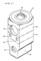
- FIG. 11 shows another example of the expansion valve 5.
- a sealing plug 9i is attached in place of the tube 9h to the hole 9g.
- the expansion valve body 5a is in the form of a column having a square cross section. Thin-walled portions 5e are formed individually on the opposite sides of the bottom portion of the body 5a, and bolt holes 5f are bored near the low-pressure refrigerant passage 5d.
- the expansion valve 5 shown in FIG. 10 is a temperature-type expansion valve that detects the outlet temperature of the evaporator 6 (temperature of the low-pressure refrigerant passage 5d) and transmits it to the temperature sensing drive element 9 of the valve 5. If the expansion valve of this type is used in a refrigeration system of an air conditioner of an automobile, for example, in general, the automobile is left for a while under relatively high-load conditions related to the outside and inside air temperatures. If the refrigerating cycle (air-cooling operation) is then started, the liquid refrigerant is fed into the evaporator at a high rate, since the opening of the expansion valve is wide. Possibly, therefore, noise may be produced when the refrigerant passes through the expansion valve.
- the high-pressure refrigerant that is fed into the expansion valve may be subjected to pressure fluctuation on the upper-stream side in the refrigerating cycle.
- This pressure fluctuation is transmitted to the valve by the medium of the high-pressure refrigerant.
- the refrigerant may possibly produce noise as it expands.
- the pressure fluctuation of the refrigerant on the upper-stream side is transmitted to the valving element, the operation of the valving element may become unstable. In this case, vibration of the valving element may possibly produce noise.
- the object of the present invention is to provide an expansion valve, which can be easily fitted with sound insulating members having simple construction and has excellent sound insulating and vibration-proof effects.
- an expansion valve comprising two case members of the same shape attached to an expansion valve body through sound insulating members.
- Each case member has retaining portions and retainable portions arranged at the upper and lower parts thereof, the retaining portion of one case member being capable of engaging the retainable portion of the other case member, and the retainable portion of the one case member being capable of engaging the retaining portion of the other case member.
- each case member is flat.
- an expansion valve comprising two sound insulating members of the same shape attached to an expansion valve body so as to cover the same.
- Each sound insulating member has retaining portions and retainable portions arranged at the upper and lower parts thereof, the retaining portion of one sound insulating member being capable of engaging the retainable portion of the other sound insulating member, and the retainable portion of the one sound insulating member being capable of engaging the retaining portion of the other sound insulating member.
- each sound insulating member is flat.
- an expansion valve comprising an expansion valve body having therein a high-pressure-side passage, low-pressure-side passage, and orifice internally connecting the passages, a valving element opposed to the orifice, and a temperature sensing drive element having a diaphragm for driving the valving element by means of an operating rod and being located outside the expansion valve body.
- the expansion valve further comprises a case member attached to the expansion valve body and the temperature sensing drive element so as to extend along the whole contours thereof except outlets and inlets of the passages in the expansion valve body.
- the case member includes two members of the same shape in engagement with each other.
- the case member is attached to the entire temperature sensing drive element except a part thereof.
- the case member is mounted through a sound insulating member.
- One of the two members constituting the case member is formed having a retaining portion, and the other member is formed having a retainable portion in a position corresponding to the retaining portion, the case member being attached to the expansion valve body and the temperature sensing drive element with the retaining portion and the retainable portion in engagement with each other.
- the retaining portion and the retainable portion are formed inside the case member.
- Each of the two members constituting the case member is formed having a retaining portion and a retainable portion, the case member being attached to the expansion valve body and the temperature sensing drive element in a manner such that the retaining portion of one of the members is in engagement with the retainable portion of the other member and that the retainable portion of the one member is in engagement with the retaining portion of the other member.
- the retaining portion and the retainable portion are arranged side by side on each member.
- a sound insulating case of an expansion valve comprising two sound insulating members of the same shape and two case members of the same shape for holding the sound insulating members.
- the expansion valve according to the present invention has the following effects.
- the two case members of the same shape are attached to the expansion valve body with the sound insulating members between them, sound insulating and vibration-proof effects can be obtained, and besides, it is necessary only that components of the same shape be prepared as the case members. Thus, the manufacturing cost can be lowered, and handling the valve can be facilitated.
- the two sound insulating members of the same shape are attached to the expansion valve body, sound insulating and vibration-proof effects can be obtained, and besides, the construction can be simplified, and handling can be made easier.
- the retaining and retainable portions are formed side by side on the respective upper and lower parts of the case members.
- the two members of the same shape can be easily mounted or removed at a stroke in a manner such that the retaining and retainable portions are caused to engage one another when the members are attached to the expansion valve body.
- each case member or sound insulating member Since the outer surface of each case member or sound insulating member is flat, handling properties, such as the ease of attachment of the expansion valve as a whole, are improved.
- the two case members of the same shape are attached to the expansion valve body, sound insulating and vibration-proof effects can be obtained, and besides, it is necessary only that components of the same shape be prepared as the case members. Thus, the manufacturing cost can be lowered, handling the valve can be facilitated, and the construction can be simplified. Further, the retaining and retainable portions are formed side by side on the respective upper and lower parts of the case members. Thus, the two members of the same shape can be easily mounted or removed at a stroke in a manner such that the retaining and retainable portions are caused to engage one another when the members are attached to the expansion valve body.
- the sound insulating case of the expansion valve is composed of the two sound insulating members of the same shape and the two case members of the same shape for holding the sound insulating members, the number of indispensable components can be reduced.
- the sound insulating case of the expansion valve 5 is composed of two sound insulating members 10A and 10B of the same shape and two case members 20A and 20B of the same shape that hold the members 10A and 10B, respectively.
- the sound insulating members 10A and 10B of the present embodiment are attached individually to the left- and right-hand sides of the expansion valve 5 (two side faces perpendicular to a side face in which a low-pressure-side passage 5c and a low-pressure refrigerant passage 5d opens).
- the inside of the sound insulating member 10A (in contact with the valve 5) is formed having a fixed width such that it extends along the external shape of the valve 5.
- the member 10A is composed of a bottom receiving portion 11 in engagement with a half of the base of the expansion valve 5, a bent portion 12 adjacent thereto, and a top cover portion 15 that engages the top portion (temperature sensing drive element 9) of the valve 5.
- the sound insulating member 10A is substantially in the form of a continuous plate as a whole.
- the end face of the bottom receiving portion 11 constitutes a bottom abutting surface 11a.
- the sound insulating members 10A and 10B are formed of synthetic resin or rubber that has high sound insulating and deadening effects and can be elastically deformed to some degree.
- the members 10A and 10B have a size such that they are compressed horizontally and vertically by a margin of, for example, about 1 mm when they are fitted in the case members 20A and 20B, respectively.
- the sound insulating members 10A and 10B need not always be elastically deformable.
- the top cover portion 15 is formed having a top lid receiving portion 13 corresponding to the base of the temperature sensing drive element 9 of the expansion valve 5 and a lid fitting groove 14 in which the top lid 9f is fitted. Further, a top recess 17 is formed in the lower surface of the top cover portion 15. A top abutting surface 15a is formed on the end face of the top cover portion 15. A rear overhang portion 16 is formed on the back surface of the top cover portion 15.
- the expansion valve 5 can be covered by means of the two sound insulating members 10A and 10B. As this is done, the top lid 9f is fitted in the respective lid fitting grooves 14 of the members 10A and 10B.
- the case members 20A and 20B are located outside the sound insulating members 10A and 10B, respectively, and hold them. Since the case members 20A and 20B have the same shape, as mentioned before, only the one case member 20A will be described below.
- the inside of the case member 20A has a fixed width and substantially the same shape as the external shape of the sound insulating member 10A.
- a bottom receiving portion 21 is formed at the bottom of the case member 20A, and a bent portion 22 is formed over the receiving portion 21.
- a rear overhang portion 26 is formed over the bent portion 22, and a top cover portion 25 is formed on the,top of the rear overhang portion 26.
- the case member 20A is substantially in the form of a continuous plate as a whole.
- An lower side face engaging portion 21a extends forward from one side portion of the bottom receiving portion 21 of the case member 20A. Further, a bottom retaining portion 23 and a bottom retainable portion 24 are projectingly arranged side by side on the lower surface of the bottom receiving portion 21.
- the bottom retaining portion 23 is in the form of a projection having a triangular profile.
- the bottom retainable portion 24 is formed of an elastic material and has an opening 24a in its center in which the bottom retaining portion 23 of the opponent case member 20B can be fitted.
- An upper side face engaging portion 27 having the same shape with the lower side face engaging portion 21a extends forward from one side portion of the top cover portion 25 of the case member 20A. Further, a top retaining portion 28 having the same shape with the bottom retaining portion 23 and a top retainable portion 29 having the same shape with the bottom retainable portion 24 are projectingly arranged side by side on the upper surface of the top cover portion 25.
- edge portions 21b having a uniform height from top to bottom are formed individually on the left- and right-hand side edge portions of the case member 20A.
- the sound insulating member 10A is first fitted on that side of the one case member 20A which faces the valve body 5a.
- the sound insulating member 10B is fitted on that side of the other case member 20B which faces the valve body 5a. Thereafter, these members are located individually on the opposite sides, left and right, of the valve body 5a.
- the bottom retainable portion 24 of the case member 20B is anchored to the bottom retaining portion 23 of the case member 20A, while the bottom retainable portion 24 of the case member 20A is anchored to the bottom retaining portion 23 of the case member 20B.
- the respective tops of the case members 20A and 20B are positioned by means of their respective upper side face engaging portions 27. Then, the top retainable portion 29 of the case member 20B is anchored to the top retaining portion 28 of the case member 20A, while the top retainable portion 29 of the case member 20A is anchored to the top retaining portion 28 of the case member 20B.
- the two case members 20A and 20B can be coupled also at their top portions by being only butted against each other.
- the two sound insulating members 10A and 10B can be securely held on the left and right, respectively, of the expansion valve body 5a, so that noise and vibration produced in the expansion valve body 5a can be attenuated, and heat insulating effect can be produced.
- bottom retaining portion 23, bottom retainable portion 24, top retaining portion 28, and top retainable portion 29 of each of the case members 20A and 20B having the same shape must only be able to be anchored to their counterparts of the opponent case member. It is to be understood, therefore, that these portions may be formed having various other shapes.
- FIGS. 4 to 6 A second embodiment will now be described with reference to FIGS. 4 to 6.
- like numerals are used to designate like elements that are common to the first and second embodiments, and a detailed description of those elements is omitted. The following is a description of only those portions which differentiate the second embodiment from the first embodiment.
- a top cover portion 15' of each of sound insulating members 10A' and 10B' has a semicircular shape as viewed from above. As shown in FIG. 5, cover extending portions 15b' are formed individually on the left- and right-hand sides of the cover portion 15'. A conical protrusion is formed on the upper surface of the top cover portion 15'. Further, a top recess 17' is formed in the lower surface of the top cover portion 15'. A top abutting surface 15a' is formed on the end face of the top cover portion 15'.
- the sound insulating members 10A' and 10B' have the same shape. When they are opposed to each other and attached individually to the opposite side faces of the expansion valve body 5a, therefore, the respective top cover portion 15' (semicircular) of the members 10A' and 10B' are coupled to each other, thereby covering the top lid 9f of the expansion valve 5 throughout the circumference. This is a feature of the second embodiment.
- a side cover portion 25a' is formed on each of the case members 20A' and 20B' so as entirely to cover the outside of the cover extending portion 15b' on its corresponding sound insulating member 10A' or 10B'. Further, a top space portion 25b' is formed under a top cover portion 25' of each case member 20A' or 20B'. The top protrusion of the top cover portion 15' of the sound insulating member 10A' can be fitted into the top space portion 25b'.
- the side cover portion 25a' and the top space portion 25b' are designed after the respective external shapes of the cover extending portion 15b' and the top cover portion 15', respectively.
- the case members 20A' and 20B' are not different from the case members 20A and 20B of the first embodiment.
- a upper side face engaging portion 27 is formed on the upper part of each top cover portion 15' so as to press the shoulder portion of its corresponding top cover portion 25'.
- the sound insulating members 10A' and 10B' and the case members 20A' and 20B' of the second embodiment may be attached to the opposite sides of the expansion valve body 5a, as shown in FIG. 4, by using the same means of the first embodiment.
- the members 10A', 10B', 20A' and 20' are attached to the valve body 5a, the top lid 9f is covered entirely, so that sound insulating effect can be obtained as well as heat insulating effect.
- FIGS. 7 to 9 A third embodiment of the invention will now be described with reference to FIGS. 7 to 9.
- like numerals are used to designate like elements that are common to the first and third embodiments, and a detailed description of those elements is omitted. The following is a description of only those portions which differentiate the third embodiment from the first embodiment.
- This embodiment is characterized in the shape of case members 20A" and 20B".
- Each of sound insulating members (not shown) that are attached individually to the members 20A" and 20B" is in the form of a flat box. The inside of this box is shaped after the side face of the expansion valve body 5a, and its outside is smooth.
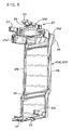
- the case members 20A" and 20B" of the present embodiment have a bottom receiving portion 21" and a top cover portion 25" each.
- a bottom retaining portion 23" is formed on one side of the bottom receiving portion 21". It is a recess of which the inner part is widened.
- a club-shaped bottom retainable portion 24" projects forward from the other side of the bottom receiving portion 21" (i.e., in a position adjacent to the bottom retaining portion 23"). It can be elastically deformed so that its width is reduced.
- a top retaining portion 28" having the same shape with the bottom retaining portion 23" is also formed on one side of the top cover portion 25" of each of the case members 20A" and 20B".
- a top retainable portion 29" having the same shape with the bottom retainable portion 24" is also formed on the other side of the top cover portion 25" so as to adjoin the top retaining portion 28".
- Edge portions 21b" having a height substantially equal to the thickness of the sound insulating members are formed individually on the opposite side edge portions of each of the case members 20A" and 20B".
- the external and internal shapes of the case members 20A" and 20B" are simple. By selecting a suitable external shape for the sound insulating members, therefore, the case members 20A" and 20B" can be formed having various external shapes, e.g., shape of an ellipse or square.
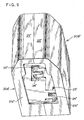
- the expansion valve that is covered by the case members 20A" and 20B" can be easily attached to a dashboard of the automobile in which a fitting hole is formed having a shape corresponding to that of a combination of the case members 20A" and 20B" coupled together (see FIGS. 8 and 9), for example.
- the bottom retaining portion 23", bottom retainable portion 24", top retaining portion 28", and top retainable portion 29" must only be able to engage one another. It is to be understood, therefore, that these portions may be formed having various other shapes.
- the expansion valve according to the present invention has the following effects.
- the two case members of the same shape are attached to the expansion valve body with the sound insulating members between them, sound insulating and vibration-proof effects can be obtained, and besides, it is necessary only that components of the same shape be prepared as the case members. Thus, the manufacturing cost can be lowered, and handling the valve can be facilitated.
- the two sound insulating members of the same shape are attached to the expansion valve body, sound insulating and vibration-proof effects can be obtained, and besides, the construction can be simplified, and handling can be made easier.
- the retaining and retainable portions are formed side by side on the respective upper and lower parts of the case members.
- the two members of the same shape can be easily mounted or removed at a stroke in a manner such that the retaining and retainable portions are caused to engage one another when the members are attached to the expansion valve body.
- each case member or sound insulating member Since the outer surface of each case member or sound insulating member is flat, handling properties, such as the ease of attachment of the expansion valve as a whole, are improved.
- the two case members of the same shape are attached to the expansion valve body, sound insulating and vibration-proof effects can be obtained, and besides, it is necessary only that components of the same shape be prepared as the case members. Thus, the manufacturing cost can be lowered, handling the valve can be facilitated, and the construction can be simplified. Further, the retaining and retainable portions are formed side by side on the respective upper and lower parts of the case members. Thus, the two members of the same shape can be easily mounted or removed at a stroke in a manner such that the retaining and retainable portions are caused to engage one another when the members are attached to the expansion valve body.
- the sound insulating case of the expansion valve is composed of the two sound insulating members of the same shape so that the two sound insulating cover members have a single configuration, the number of indispensable components can be reduced.
Landscapes
- Physics & Mathematics (AREA)
- Engineering & Computer Science (AREA)
- Fluid Mechanics (AREA)
- Mechanical Engineering (AREA)
- Thermal Sciences (AREA)
- General Engineering & Computer Science (AREA)
- Temperature-Responsive Valves (AREA)
- Details Of Valves (AREA)
- Air-Conditioning For Vehicles (AREA)
Applications Claiming Priority (2)
| Application Number | Priority Date | Filing Date | Title |
|---|---|---|---|
| JP2002072852A JP4462807B2 (ja) | 2002-03-15 | 2002-03-15 | 膨張弁又は膨張弁用ケース |
| JP2002072852 | 2002-03-15 |
Publications (3)
| Publication Number | Publication Date |
|---|---|
| EP1344966A2 true EP1344966A2 (de) | 2003-09-17 |
| EP1344966A3 EP1344966A3 (de) | 2004-04-21 |
| EP1344966B1 EP1344966B1 (de) | 2010-08-25 |
Family
ID=27764572
Family Applications (1)
| Application Number | Title | Priority Date | Filing Date |
|---|---|---|---|
| EP20030005392 Expired - Lifetime EP1344966B1 (de) | 2002-03-15 | 2003-03-13 | Entspannungsventil |
Country Status (6)
| Country | Link |
|---|---|
| US (1) | US6824068B2 (de) |
| EP (1) | EP1344966B1 (de) |
| JP (1) | JP4462807B2 (de) |
| KR (1) | KR20030074134A (de) |
| CN (1) | CN1320300C (de) |
| DE (1) | DE60333884D1 (de) |
Cited By (1)
| Publication number | Priority date | Publication date | Assignee | Title |
|---|---|---|---|---|
| CN111365911A (zh) * | 2020-03-23 | 2020-07-03 | 浙江农林大学暨阳学院 | 一种膨胀阀及汽车空调系统 |
Families Citing this family (8)
| Publication number | Priority date | Publication date | Assignee | Title |
|---|---|---|---|---|
| KR101094847B1 (ko) * | 2004-07-19 | 2011-12-15 | 한라공조주식회사 | 팽창밸브 조립체 |
| KR20060081922A (ko) * | 2005-01-11 | 2006-07-14 | 삼성전자주식회사 | 냉장고 |
| KR100747326B1 (ko) | 2006-02-02 | 2007-08-07 | 기아자동차주식회사 | 탄성부재를 이용한 에어컨 팽창밸브 부식 열해 방지커버 |
| CN101836058B (zh) * | 2007-10-24 | 2014-03-12 | 株式会社不二工机 | 膨胀阀 |
| CN102858564B (zh) * | 2010-04-26 | 2015-11-25 | 丰田自动车株式会社 | 车辆用空调装置 |
| CN103574998B (zh) * | 2012-08-02 | 2015-12-16 | 珠海格力电器股份有限公司 | 固定装置及包括该固定装置的空调机 |
| CN103644689A (zh) * | 2013-11-28 | 2014-03-19 | 博耐尔汽车电气系统有限公司 | 一种汽车空调器膨胀阀 |
| CN105909863B (zh) * | 2016-06-29 | 2018-01-12 | 博耐尔汽车电气系统有限公司 | 一种膨胀阀的使用方法 |
Citations (1)
| Publication number | Priority date | Publication date | Assignee | Title |
|---|---|---|---|---|
| JP2002029251A (ja) | 2000-07-14 | 2002-01-29 | Denso Corp | 車両用空調装置 |
Family Cites Families (15)
| Publication number | Priority date | Publication date | Assignee | Title |
|---|---|---|---|---|
| US37423A (en) * | 1863-01-13 | Improvement in tea-kettles | ||
| US3915185A (en) * | 1965-05-18 | 1975-10-28 | Santron Corp | Control units for flow control systems |
| IT986479B (it) * | 1973-06-18 | 1975-01-30 | Marocco A | Perfezionamenti nelle elettroval vole differenziali per il control lo di fluidi |
| US4342421A (en) * | 1981-02-23 | 1982-08-03 | General Motors Corporation | Thermostatic expansion valve for a refrigeration system |
| US4984735A (en) * | 1990-03-19 | 1991-01-15 | Eaton Corporation | Sensing refrigerant temperature in a thermostatic expansion valve |
| EP0539944A3 (en) * | 1991-10-31 | 1993-08-04 | Eaton Corporation | Expansion valve and temperature sensing assembly therefor |
| EP0659600B1 (de) * | 1993-12-22 | 1999-08-04 | Calsonic Corporation | Rohranordnung einer Kraftfahrzeug-Klimaanlage |
| JP2001171337A (ja) * | 1994-12-22 | 2001-06-26 | Fuji Koki Corp | 温度膨張弁 |
| JP3207716B2 (ja) * | 1994-12-22 | 2001-09-10 | 株式会社不二工機 | 温度膨張弁 |
| JP2000203251A (ja) | 1999-01-12 | 2000-07-25 | Zexel Corp | ク―リングユニットの取付構造 |
| JP2000310352A (ja) * | 1999-04-27 | 2000-11-07 | Denso Corp | 温度式膨張弁およびその製造方法 |
| JP2001199230A (ja) * | 1999-11-10 | 2001-07-24 | Fuji Koki Corp | 温度膨張弁 |
| JP3669885B2 (ja) | 1999-11-25 | 2005-07-13 | 株式会社デンソー | 車両用空調装置 |
| JP2002061989A (ja) | 2000-08-22 | 2002-02-28 | Denso Corp | 空調装置用膨張弁 |
| JP3943843B2 (ja) | 2001-02-14 | 2007-07-11 | 株式会社テージーケー | 膨張弁用防音カバー |
-
2002
- 2002-03-15 JP JP2002072852A patent/JP4462807B2/ja not_active Expired - Fee Related
- 2002-08-09 CN CNB021297312A patent/CN1320300C/zh not_active Expired - Fee Related
-
2003
- 2003-02-07 KR KR10-2003-0007724A patent/KR20030074134A/ko not_active Withdrawn
- 2003-02-14 US US10/366,443 patent/US6824068B2/en not_active Expired - Fee Related
- 2003-03-13 EP EP20030005392 patent/EP1344966B1/de not_active Expired - Lifetime
- 2003-03-13 DE DE60333884T patent/DE60333884D1/de not_active Expired - Lifetime
Patent Citations (1)
| Publication number | Priority date | Publication date | Assignee | Title |
|---|---|---|---|---|
| JP2002029251A (ja) | 2000-07-14 | 2002-01-29 | Denso Corp | 車両用空調装置 |
Cited By (1)
| Publication number | Priority date | Publication date | Assignee | Title |
|---|---|---|---|---|
| CN111365911A (zh) * | 2020-03-23 | 2020-07-03 | 浙江农林大学暨阳学院 | 一种膨胀阀及汽车空调系统 |
Also Published As
| Publication number | Publication date |
|---|---|
| EP1344966A3 (de) | 2004-04-21 |
| US6824068B2 (en) | 2004-11-30 |
| JP2003269823A (ja) | 2003-09-25 |
| EP1344966B1 (de) | 2010-08-25 |
| DE60333884D1 (de) | 2010-10-07 |
| KR20030074134A (ko) | 2003-09-19 |
| US20030172668A1 (en) | 2003-09-18 |
| CN1445471A (zh) | 2003-10-01 |
| CN1320300C (zh) | 2007-06-06 |
| JP4462807B2 (ja) | 2010-05-12 |
Similar Documents
| Publication | Publication Date | Title |
|---|---|---|
| US7036527B2 (en) | Composite valve | |
| US20040026524A1 (en) | Expansion valve | |
| EP1344966B1 (de) | Entspannungsventil | |
| CN100394126C (zh) | 膨胀阀 | |
| US5943871A (en) | Thermal expansion valve | |
| US6702188B2 (en) | Expansion valve | |
| US6427243B2 (en) | Thermal expansion valve | |
| US5732570A (en) | Thermal expansion valve and air conditioning apparatus using the same | |
| JP2000016068A (ja) | 温度自動膨張弁 | |
| JP6569061B2 (ja) | 制御弁 | |
| US6209793B1 (en) | Thermostatic expansion valve in which a valve seat is movable in a flow direction of a refrigerant | |
| US20040007015A1 (en) | Expansion valve | |
| JPWO2006090826A1 (ja) | 圧力制御弁 | |
| JP2001012824A (ja) | 制御弁 | |
| EP1209426A1 (de) | Entspannungsventil | |
| JP4364114B2 (ja) | 圧力制御弁 | |
| JP3943843B2 (ja) | 膨張弁用防音カバー | |
| CN100543384C (zh) | 用于致冷系统中的膨胀阀和致冷系统 | |
| JP2007278563A (ja) | 圧力制御弁 | |
| JP4743926B2 (ja) | 膨張弁 | |
| JP2001241812A (ja) | 膨張弁 | |
| JPH0979703A (ja) | 温度式膨張弁 | |
| US20100180613A1 (en) | Expansion valve | |
| JPH109720A (ja) | 温度式膨張弁 | |
| JPH08210734A (ja) | 温度式膨張弁 |
Legal Events
| Date | Code | Title | Description |
|---|---|---|---|
| PUAI | Public reference made under article 153(3) epc to a published international application that has entered the european phase |
Free format text: ORIGINAL CODE: 0009012 |
|
| AK | Designated contracting states |
Kind code of ref document: A2 Designated state(s): AT BE BG CH CY CZ DE DK EE ES FI FR GB GR HU IE IT LI LU MC NL PT RO SE SI SK TR |
|
| AX | Request for extension of the european patent |
Extension state: AL LT LV MK |
|
| PUAL | Search report despatched |
Free format text: ORIGINAL CODE: 0009013 |
|
| AK | Designated contracting states |
Kind code of ref document: A3 Designated state(s): AT BE BG CH CY CZ DE DK EE ES FI FR GB GR HU IE IT LI LU MC NL PT RO SE SI SK TR |
|
| AX | Request for extension of the european patent |
Extension state: AL LT LV MK |
|
| RIC1 | Information provided on ipc code assigned before grant |
Ipc: 7F 16K 27/00 B Ipc: 7F 25B 41/06 A |
|
| 17P | Request for examination filed |
Effective date: 20040917 |
|
| AKX | Designation fees paid |
Designated state(s): DE FR GB IT |
|
| 17Q | First examination report despatched |
Effective date: 20070322 |
|
| GRAP | Despatch of communication of intention to grant a patent |
Free format text: ORIGINAL CODE: EPIDOSNIGR1 |
|
| GRAS | Grant fee paid |
Free format text: ORIGINAL CODE: EPIDOSNIGR3 |
|
| GRAA | (expected) grant |
Free format text: ORIGINAL CODE: 0009210 |
|
| AK | Designated contracting states |
Kind code of ref document: B1 Designated state(s): DE FR GB IT |
|
| REG | Reference to a national code |
Ref country code: GB Ref legal event code: FG4D |
|
| REF | Corresponds to: |
Ref document number: 60333884 Country of ref document: DE Date of ref document: 20101007 Kind code of ref document: P |
|
| PLBE | No opposition filed within time limit |
Free format text: ORIGINAL CODE: 0009261 |
|
| STAA | Information on the status of an ep patent application or granted ep patent |
Free format text: STATUS: NO OPPOSITION FILED WITHIN TIME LIMIT |
|
| 26N | No opposition filed |
Effective date: 20110526 |
|
| REG | Reference to a national code |
Ref country code: DE Ref legal event code: R097 Ref document number: 60333884 Country of ref document: DE Effective date: 20110526 |
|
| GBPC | Gb: european patent ceased through non-payment of renewal fee |
Effective date: 20110313 |
|
| PG25 | Lapsed in a contracting state [announced via postgrant information from national office to epo] |
Ref country code: GB Free format text: LAPSE BECAUSE OF NON-PAYMENT OF DUE FEES Effective date: 20110313 |
|
| REG | Reference to a national code |
Ref country code: DE Ref legal event code: R084 Ref document number: 60333884 Country of ref document: DE Effective date: 20140430 |
|
| PG25 | Lapsed in a contracting state [announced via postgrant information from national office to epo] |
Ref country code: IT Free format text: LAPSE BECAUSE OF NON-PAYMENT OF DUE FEES Effective date: 20150313 |
|
| REG | Reference to a national code |
Ref country code: FR Ref legal event code: PLFP Year of fee payment: 14 |
|
| REG | Reference to a national code |
Ref country code: FR Ref legal event code: PLFP Year of fee payment: 15 |
|
| REG | Reference to a national code |
Ref country code: FR Ref legal event code: PLFP Year of fee payment: 16 |
|
| PG25 | Lapsed in a contracting state [announced via postgrant information from national office to epo] |
Ref country code: IT Free format text: LAPSE BECAUSE OF NON-PAYMENT OF DUE FEES Effective date: 20150313 |
|
| PGRI | Patent reinstated in contracting state [announced from national office to epo] |
Ref country code: IT Effective date: 20180104 |
|
| PGFP | Annual fee paid to national office [announced via postgrant information from national office to epo] |
Ref country code: DE Payment date: 20200303 Year of fee payment: 18 Ref country code: IT Payment date: 20200221 Year of fee payment: 18 |
|
| PGFP | Annual fee paid to national office [announced via postgrant information from national office to epo] |
Ref country code: FR Payment date: 20200214 Year of fee payment: 18 |
|
| REG | Reference to a national code |
Ref country code: DE Ref legal event code: R079 Ref document number: 60333884 Country of ref document: DE Free format text: PREVIOUS MAIN CLASS: F25B0041060000 Ipc: F25B0041300000 |
|
| REG | Reference to a national code |
Ref country code: DE Ref legal event code: R119 Ref document number: 60333884 Country of ref document: DE |
|
| PG25 | Lapsed in a contracting state [announced via postgrant information from national office to epo] |
Ref country code: DE Free format text: LAPSE BECAUSE OF NON-PAYMENT OF DUE FEES Effective date: 20211001 Ref country code: FR Free format text: LAPSE BECAUSE OF NON-PAYMENT OF DUE FEES Effective date: 20210331 |
|
| PG25 | Lapsed in a contracting state [announced via postgrant information from national office to epo] |
Ref country code: IT Free format text: LAPSE BECAUSE OF NON-PAYMENT OF DUE FEES Effective date: 20210331 |